
Morningstar ProStar MPPT Manual


Installation Instructions26
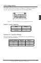
STEP 1: Check Controller Limitations
Verify that the highest temperature compensated solar array
open-circuit voltage (Voc), and load current do not exceed
the ratings of the ProStar MPPT version being installed.
Multiple controllers can be installed in parallel on the same
battery bank to achieve greater total charging current. In
this type of system, each ProStar MPPT must have its own
solar array. The load terminals of multiple controllers can
only be wired together if the total load draw does not ex-
ceed the nameplate current of the LOWEST rated controller.
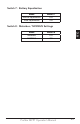
STEP 2: Battery Voltage Sense Wires
Due to connection and cable resistance, voltage drops are
unavoidable in power cables that carry current, including the
ProStar MPPT battery cables. If Battery Sense wires are not
used, the controller must use the voltage reading at the bat-
tery power terminals for regulation. This voltage may differ
from the actual battery bank voltage due to voltage drop.
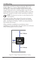
Battery Voltage Sense is a high impedance connection that
enables the ProStar MPPT to measure the battery termi-
nal voltage precisely with small gauge wires that have no
voltage drop. When connected directly to the battery, the
sense wires will improve battery charging accuracy. Battery
voltage sense wires are recommended if the controller is
more than three meters (10 ft) from the battery.
Generally accepted wiring practice is to limit voltage drops
between the charger and the battery to 2%. Even properly
sized wiring with 2% drop can result in a 0.3 volt drop for
14.4V charging. Voltage drops will cause some undercharg-
ing of the battery. The controller will begin Absorption or
limit equalization at a lower battery voltage because the
controller measures a higher voltage at the controller’s ter-
minals than is the actual battery voltage. For example, if the
controller is programmed to start Absorption at 14.4V, when
the controller "sees" 14.4 volts at its battery terminals,