MultiModem® GPRS USB Wireless Modem MTCBA-G-U User Guide
Copyright and Technical Support MultiModem® GPRS USB External Wireless Modem User Guide Model MTCBA-G-U S000346J, Revision J Copyright This publication may not be reproduced, in whole or in part, without prior expressed written permission from MultiTech Systems, Inc. All rights reserved. Copyright © 2007 by Multi-Tech Systems, Inc. Multi-Tech Systems, Inc.
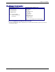
Table of Contents Contents Chapter 1 – Product Description and Specifications................................................................................................4 Product Description.................................................................................................................................................4 Features..................................................................................................................................................................
Chapter 1 – Product Description and Specifications Chapter 1 – Product Description and Specifications Product Description The Multi-Tech MultiModem GPRS-U is an external data/fax/voice wireless modem with a USB interface. It supports mobile originated short message service (SMS) and mobile-terminated SMS. Designed for global use, it offers standards-based multi-band GSM/GPRS Class 10 performance.
Chapter 2 – Installation Application Overview Application Types With circuit switched data rates up to 14.4K bps, the MultiModem GPRS is targeted at applications that periodically need to send or receive data over a wireless network. It is an ideal solution for: Appliances ATM Terminals Automotive Data Collection Gas Pumps Industrial and Medical Remote Monitoring Systems Remote Diagnostics Remote Metering Security Systems Vending/Gaming Machines Other devices requiring wireless connectivity.
Chapter 2 – Installation Safety General Safety The modem is designed for and intended to be used in fixed and mobile applications. “Fixed” means that the device is physically secured at one location and is not able to be easily moved to another location. “Mobile” means that the device is designed to be used in other than fixed locations. Caution: Maintain a separation distance of at least 20 cm (8 inches) is normally maintained between the transmitter’s antenna and the body of the user or nearby persons.
Chapter 2 – Installation Package Contents Single Package (one unit) 1 modem 1 mounting bracket 1 Quick Start Guide 1 MultiModem CD Note: You must supply: Screws for the bracket An antenna Bundled Package (multiple units) Each individual package in the bundle includes the following: 1 modem 1 mounting bracket 1 USB cable 1 or 2 antennas 4 rubber feet 1 Quick Start Guide 1 MultiModem CD Note: You must supply screws for the bracket.
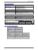
Chapter 2 – Installation Specifications General Specifications Mechanical Dimensions & Weight Connectors & Fasteners Operating Temperatures Storage Temperatures Humidity Certifications 4.3" L x 2.4" W x 0.94" H; 4.2 oz. (11 cm x 6.1 cm x 2.
Chapter 2 – Installation Interfaces The Wireless MultiModem has several interfaces: • LED function indicating operating status • External antenna (via SMA connector) • Serial and control link (via USB connector) • Microphone and speaker (via handset jack) • SIM card holder LEDs LED Indicators TD RD CD LS TR PWR Transmit Data. Lit when modem is transmitting data. Receive Data. Lit when modem is receiving data. Carrier Detect. Lit when data connection has been established. Line Status.
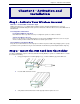
Chapter 2 – Activation and Installation Chapter 2 – Activation and Installation Step 1 – Activate Your Wireless Account Multi-Tech – A Certified National Activation Agent Multi-Tech Systems, Inc. is a certified national activation agent for Cingular and Sprint wireless. For more information about available data plans and to purchase and activate a wireless data account, contact Multi-Tech at 888-288-5470.
Chapter 3 – Using Your Wireless Modem Step 3 – Connect the Antenna and USB Cable • Antenna. Connect a suitable antenna to the SMA connector (See antenna specifications in Chapter 1). • USB Cable. Connect one end of the USB cable to the modem and the other end to the PC. Step 4 – Handset Connection (Optional) If you intend to use a phone handset, connect it to the MultiModem now. Multi-Tech Systems, Inc.
Chapter 3 – Using Your Wireless Modem Step 5 – Attach the Modem to a Flat Surface (Optional) To mount the Wireless MultiModem, do the following: 1. Obtain mounting screws (two are needed) that are appropriate for the surface on which you will mount the MultiModem. For example, one might use two 6-32 self-tapping screws 5/8” in length to mount the unit in a truck to the wall of the cab behind the passenger’s seat. 2. Typically, the unit is mounted against a flat surface into which holes can be drilled.
Chapter 3 – Using Your Wireless Modem Step 6 – Install the Modem Driver Introduction Compatibility: This wireless MultiModem is compatible with Windows Operating Systems 2000/2003/XP and Linux. Windows Drivers: The wireless MultiModem USB driver must be installed in your computer’s program directory. The procedure differs depending on the operating system and how it is set up. The drivers are located on the MultiModem CD.
Chapter 3 – Using Your Wireless Modem 4. Click on Install from a list or specific location (Advanced). 5. Click Next. 6. The next screen is the Please choose your search and installation options. Ensure that Search for the best driver in these locations with Search removable media (floppy, CD-ROM…) is selected. Click Next. 7. A Windows Logo Testing screen may appear. Some operating systems may not give you this screen. Click Continue Anyway. 8.
Chapter 3 – Using Your Wireless Modem Part B for Windows XP/2003: Associating PC Port with USB Driver 1. If the Welcome to the Found New Hardware Wizard screen – Can Windows connect to Windows update to search for software? appeared when you were installing the driver, it will come up here also. Select No, not this time. Then click Next. 2. The Welcome to the Found New Hardware Wizard screen will appear with the Texas Instruments UMP Serial Port as the device to be installed.
Chapter 3 – Using Your Wireless Modem Part C for Windows XP/2003: Installing the Modem INF File 1. If the Welcome to the Found New Hardware Wizard screen asking – Can Windows connect to Windows update to search for software? appears again, select No, not this time. Then click Next. 2. The Found New Hardware Wizard screen appears for the Multi-Tech – GPRS Modem. 3. Click on Install from a list or specific location (Advanced). Then click Next. 4.
Chapter 3 – Using Your Wireless Modem Installing the Modem Driver in Windows 2000 Part A for Windows 2000: Installing the USB Driver 1. Connect the USB cable between the MultiModem and the PC. 2. Insert the MultiModem CD into your CD-ROM drive. The CD uses the Autorun feature, and after a brief delay, the MultiModem Setup – Welcome screen appears. Close the Welcome screen. 3. After a brief delay, the Welcome to the Found New Hardware Wizard screen appears.
Chapter 3 – Using Your Wireless Modem 7. The Driver Files Search Results screen appears. The wizard has found the wrong driver. Click on Install one of the other drivers. Click Next. 8. At the Driver Files Found screen, choose the GPRS Device from the listing. Click Next. 9. A Digital Signature Not Found screen may appear depending on operating system settings. Click Yes. 10. At the Completing the Found New Hardware Wizard screen, click Finish. Installation of the USB driver is now complete.
Chapter 3 – Using Your Wireless Modem Part B for Windows 2000: Associating PC Port with USB Driver 1. Wait while Windows prepares the next phase of the installation (associating the PC port with the USB drive). When the Welcome to the Found New Hardware Wizard screen appears, click Next. 2. The Install Hardware Device Drivers screen appears referring to the Texas Instrument UMP Serial Port. This is the beginning of the “Found New Hardware” sequence for the port.
Chapter 3 – Using Your Wireless Modem Part C for Windows 2000: Installing the Modem INF File 1. After a brief delay, the Welcome to the Found New Hardware Wizard screen appears. Click Next. 2. The Install Hardware Device Drivers screen appears, referring to the Multi-Tech GPRS modem. Click on Search for a suitable driver for my device (recommended). Click Next. 3. The Locate Drivers Files screen appears. Ensure that CD-ROM drive is the only option checked. Click Next. 4.
Chapter 2 – Activation and Installation Chapter 3 – Using Your Wireless Modem Phone Number for the Wireless Modem • • Every wireless modem will have its own unique phone number. The wireless modem’s phone number may simply be told to the subscriber or be on the SIM or both. Wireless provider implementations may vary. Examples of Useful AT Commands A Note About HyperTerminal In order to verify signal strength and roaming status, you must use a terminal application such as HyperTerminal.
Chapter 3 – Using Your Wireless Modem Establishing a Voice Call • Enter PIN Code (if required by your wireless provider) Type AT+CPIN=1234 Responses: OK (PIN Code accepted) +CME ERROR : 16 (Incorrect PIN Code) +CME ERROR : 3 (PIN already entered [with +CMEE : 1 mode]) • Initiate a voice call Type ATD1234; (Note: Don’t forget the semicolon “;” at the end.
Chapter 3 – Using Your Wireless Modem Using Short Message Services (SMS) Send a Short Message to a Specified Number. Type AT+CMGS="8585551212" Then type your message: Please call me soon. The modem may respond with +CMGS: OK Write a Message to Memory. You can store a message to send it at a later date. Type AT+CMGW="8585551212" Type the message. The modem may respond with +CMGW: 4 OK (The message is stored in the index as message 4.
Chapter 3 – Using Your Wireless Modem SMS Examples Send Example Send an SMS message to another SMS compatible device at+cmgf=1 (set to text mode) OK at+cpms="SM","SM" (set memory storage when writing and sending SMS messages) +CPMS: 0,50,0,50 OK at+cmgs="7632273726" (send message to the number specified in quotes) > TEST message ONE.
Chapter 3 – Using Your Wireless Modem Receive Example 3: Receive SMS message in text mode by directly routing the received message to the TE through the serial port using Phase 2+: at+cmgf=1 (set to text mode) OK at+csms=1 (set to Phase 2+) +CSMS: 1,1,1 OK at+cnmi=2,2,0,0,0 (set to receive SMS and route directly to TE) OK +CMT: "+17632273726",,"06/03/17,14:01:17+00" (message received and directly routed to TE) TEST3 at+cnma (acknowledge that message has been received) OK Multi-Tech Systems, Inc.
Chapter 3 – Using Your Wireless Modem Internet Access Internet access can be setup in Windows Dial-Up Networking (DUN) of the computer that the wireless modem is serving. Setup procedures will vary according to the type of wireless service provider used. To access Dial-Up Networking on your PC, go to Start > Settings > Network Connections. • For GSM-without-GPRS, a circuit-switched data connection is used. The user can set up DUN to make a conventional V.
Chapter 3 – Using Your Wireless Modem Create Your Dial-Up Connection in Windows XP/2003 1. Click on Start and then click on Control Panel. 2. In the Control Panel, double-click on Network Connections. 3. On the Network Connections screen on the left-hand side under Network Tasks, click on Create a new connection. 4. The New Connection Wizard should appear. It will walk you through setting up your Internet connection. Click on Next > to begin. 5.
Chapter 3 – Using Your Wireless Modem Mobile PhoneTools For initial configuration of your wireless device, Multi-Tech offers a Windows® based mobile PhoneTools Mobile PhoneTools is a communication software program included on your MultiModem CD. You can install this program onto your PC and use it for making Internet connections, voice calls, SMS messaging, and email. This program allows you to use your wireless modem hooked up to your PC as if it were a cell phone. Multi-Tech Systems, Inc.
Chapter 4 – Troubleshooting and Frequently Asked Questions Chapter 4 – Troubleshooting and Frequently Asked Questions Troubleshooting Examples Before calling the Multi-Tech Technical Support, check to the following connections: • The right antenna is connected to the modem • The serial cable connection is correct • The power is connected correctly and the power lights on the modem are on • Verify your signal strength • Verify your network registration • Use the following situation examples to troubleshoot
Chapter 4 – Troubleshooting and Frequently Asked Questions Frequently Asked Questions Which providers can I use? • Two major providers are T-Mobile and Cingular. • We are Cingular approved. Does this modem support High-Speed Circuit-Switched Data (HSCSD)? • No, our GSM/GPRS modems do not support HSCSD. The modem is answering, but seems to not be doing anything? • The modem is answering in voice mode. • If you are trying to make a data call, make sure the account has CSD service.
Chapter 4 – Troubleshooting and Frequently Asked Questions After changing the +CNMI, +CSCA, or +CSMP command values, the modem doesn’t store them. • When changing these command values, you must use the +CSAS command to store the changes. How do I send an SMS message to an email account? • When sending an SMS message to an email account, you must use a designated routing number that will tell the SMS server to route your message to an email account.
Chapter 5 – Reference Information Chapter 5 – Reference Information Wireless Modem Reference Information GSM reference documents: ETSI contact: GSM 03.40, GSM 03.45, GSM 04.11,GSM 04.21, GSM05.08, GSM 07.01,GSM 07.02, GSM 07.05, GSM 07.07. ETSI Secretariat F-06921 Sophia Antipolis Cedex, France e-mail: secretariat@etsi.fr Service: The AT commands manual is available on the Multi-Tech web site: http://www.multitech.com Multi-Tech Systems, Inc.
Appendix A – Warranty and Repairs Appendix A – Warranty and Repairs Multi-Tech Warranty Statement Multi-Tech Systems, Inc., (hereafter “MTS”) warrants that its products will be free from defects in material or workmanship for a period of two, five, or ten years (depending on model) from date of purchase, or if proof of purchase is not provided, two, five, or ten years (depending on model) from date of shipment.
Appendix A – Warranty and Repairs Repair Procedures for International Customers (Outside U.S.A. and Canada) Your original point-of-purchase Reseller may offer the quickest and most economical repair option for your Multi-Tech product. You may also contact any Multi-Tech sales office for information about the nearest distributor or other repair service for your Multi-Tech product. The Multi-Tech sales office directory is available at www.multitech.
Appendix B – WEEE Statement Appendix B - Waste Electrical and Electronic Equipment (WEEE) Statement July, 2005 The WEEE directive places an obligation on EU-based manufacturers, distributors, retailers and importers to takeback electronics products at the end of their useful life. A sister Directive, ROHS (Restriction of Hazardous Substances) complements the WEEE Directive by banning the presence of specific hazardous substances in the products at the design phase.