Models MTA128ST and MTA128NT External ISDN Terminal Adapter User Guide
User Guide Model MTA128ST/NT S000305C Rev. C This publication may not be reproduced, in whole or in part, without prior written permission from Multi-Tech Systems, Inc. All rights reserved. Copyright © 2004- 07 by Multi-Tech Systems, Inc. Multi-Tech Systems, Inc. makes no representations or warranties with respect to the contents hereof and specifically disclaims any implied warranties of merchantability or fitness for any particular purpose. Furthermore, Multi-Tech Systems, Inc.
Contents Contents Chapter 1: Introduction and Description ........................................................................................................................ 4 Welcome to the world of ISDN communications. ................................................................................................................ 4 Product Description.......................................................................................................................................................
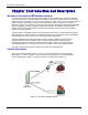
Introduction and Description Chapter 1: Introduction and Description Welcome to the world of ISDN communications. You have acquired one of the finest ISDN terminal adapters (TAs) available today, model MTA1 28ST/NT from Multi-Tech Systems. The MTA128ST is a desktop TA with an S/T interface port to connect itto the ISDN network and an analog port to connect it to a telephone, modem, or fax machine.
Introduction and Description Your ISDN TA is compatible with prevalent ISDN switch protocols. It communicates using ISDN BRI (2B+D) service, which provides up to 128K bps data communications. This manual documents the following models: • MTA1 28ST for S/T interface with one POTS port • MTA1 28NT for U interface with one POTS port Some analog devices, including telephone set, answering machine, and modem, can be connected to the POTS port via an RJ-1 1 jack.
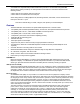
Introduction and Description If your ISDN product operates with a S/T outlet interface, you need an NT1 device to connect to the ISDN switch. MTA128ST adapters need an NT1 device to connect to the ISDN switch, but the MTA128NT adapter does not require NT1 device. In the UK, and in many European countries, NT1 device is supplied by your telephone company. Figure 2-1 ISDN Interface Points S/T Interlace The S/T interface uses an 8-conductor modular cable terminated with an 8-pin RJ-45 plug.
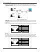
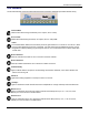
Introduction and Description LED Indicators The ten LED indicators on the front panel (see figure below) of the MTA1 28ST/NT report status and line activity. Transmit Data Flashes when data is being transmitted (on for a space, off for a mark). Receive Data Flashes when data is being received (on for a space, off for a mark). Link Status For EuroISDN NET3, INS64, and VN4 switch protocols, lights when the TA is turned on.
Introduction and Description Data Protocol V.110 V.120 X.
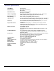
Introduction and Description Technical Specifications Trade Name Model Number Network Interface Switch Compatibiltiy B-Channel Protocols Voice Coding LED Indicators Data Rates Async Data Format Data Connections Command Interface Connectors Serial Interfaces Switches Power Requirements Dimensions Environmental Power Consumption Weight Warranty Iway Hopper™ MTA128ST (International), MTA128NT ST-Four-wire S/T interface NT-2-wire “U” interface EuroISDN (ETSI/DSS1/NET3), VN4, INS64, U.S.
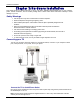
Hardware Installation Chapter 2: Hardware Installation This chapter shows you step-by-step how to set up your MTA1 28ST/NT terminal adapter (TA) to your computer, power, network terminator, and an auxiliary analog device. Please follow these instructions carefully to avoid damage to your TA. Safety Warnings • Use this product only with UL-listed and CUL-listed computers. • Never install phone wiring during a lightning storm.
Hardware Installation Turn on the TA by sliding the power switch to ON and verify operation by observing the LEDs on the front panel. The LEDs first flash in a self-test pattern. Then the LS LED remains on. If the TA does not appear to be working, Refer to Chapter 5 for troubleshooting help. Connect the TA to Your PC (RS-232 Connection) Plug one end of the RS-232 serial cable into the RS-232 connector on the modem, and plug the other end into a serial port connector on your computer, such as COM1 or COM2.
Configuration Utilities Chapter 3: Configuration Utilities Introduction You can configure the MTA128ST/NT to match your ISDN service and the remote terminal adapter (TA) with any of four methods listed below: • ISDN TA Configuration Utility This configuration utility is recommended for computers running Windows 98/NT/ME operating systems. Because it is a software-based utility, you can use it to create and store as many configurations as you want.
Configuration Utility Voice TEI___________________________________________ Voice TEI is the TEI assigned to the voice channel. Choices are: Auto TEI, a fixed TEI number, or Disable. AT command: *!D3..... Data MSN __________________________________________ The Data MSN (multiple subscriber number) allows a caller to specify an individual TA when more than one TA is connected to you network terminator. If you don’t assign a value to the MSN, the TA accepts all incoming calls.
Configuration Utility V.120 Protocol—Similar to V.1 10 protocol, but provides rates up to 64000 bps on each B channel. X.75 Protocol—Packet-switched network protocol for international use. Layer 2 portion of this protocol is used commonly as a rate adaption protocol. MLPPP Protocol—MLPPP (Multi-Link PPP) protocol provides rates up to 64 Kbps per channel. This protocol uses both B channels at once, providing an aggregate data transmission speed of 128 Kbps.
Configuration Utility DCD Drop Time _____________________________________ Sets the time, in 0.1-second increments, that a carrier must be lost before the TA disconnects. The default value is 0.7 seconds; however, you can set it anywhere in the range 0–254 (0–25.4 seconds). Setting DCD Drop Time to 255 causes the TA not to disconnect with loss of carrier when DCD Control is set to Momentary Drop.
Configuration Utility Configuring your TA If you use Windows 98/Me/NT, perform the following procedure using the Configuration Utility provided on your system CD. If you are using another operating system, you can configure the TA using the firmware-based configuration utility or AT commands. Procedures for using the firmware-based configuration utility and AT commands are described in Appendix E.
Configuration Utility 3. Searching for TA screen is displayed with please wait while the configuration utility searches for your ISDN TA(s). This may take up to 20 seconds. Then the Searching for TA screen with Devices have been identified. Please select a device to configure Click Next to continue. 4. The Configuration screen is displayed with Select the type of setup, custom building a new configuration, custom with an existing configuration, or express with an existing configuration.
Configuration Utility 5. The Network Switch Type screen is displayed with Please select the settings for the Network Switch Type. Select the network switch type you listed in the Before You Start section of this chapter. 6. Please select the settings for dynamic bandwidth allocation, high and low sampling period and throughput, and call bumping. Click Next to continue.
Configuration Utility 7. The TEI (Terminal Endpoint Identifier) screen is displayed with Please select the settings you would like for Data TEI and Voice TEI. The TEI is a unique number assigned to the TA at subscription time. The TEI is used by the telephone central office (CO) to identify the various TAs connected to the ISDN network. The TEI number can be fixed (range 0 63) or dynamic and is assigned automatically at the CO each time the TA connects to the ISDN interface and powers up.
Configuration Utility and tracking. A SPID is assigned by your local ISDN provider when you subscribe, they are in the form of a string of up to 20 characters. A SPID points to a specific location in the provider’s central office memory where service and feature parameters are stored. Click Next when you have entered your SPID information. 9. The Call Control Setup screen is displayed with Please select the settings for call control.
Configuration Utility 10. The Data Protocol Setup screen is displayed with Please select the setting you desire for the Data Protocol. If you would like the TA to detect the data protocol of an incoming data call and automatically change the TA’s protocol to match the incoming call, click auto protocol detection check box. Click Next to continue. 11. The Stored Numbers screen is displayed with Please enter the numbers you would like to store.
Configuration Utility 12. The Port Control Setup 1 screen is displayed with Please select the settings you would like for the DTR detect time, DCD drop time, DTR, DSR, CTS, and DCD signals. lick Next when you have finished entering your settings. 13. The Port Control Setup II screen is displayed with Please select the settings you would like for the Default Parity, Default Bit Rate, number of Data Bits, number of Stop Bits, Flow Control, and synchronous mode. Click Next when you are finished.
Configuration Utility 14. The POTS Port screen is displayed with Please select the settings for the PORTS port. When your selections are complete, click Next. 15 The Save Configuration screen is displayed with Please enter the name to store the configuration as in the .ini file. You can enter any name up to 35 characters or less in the Store Configuration as: window. Click Next after you have selected a name.
Configuration Utility 16. The Load Configuration screen is displayed with To load the configuration now, click Next. 17. Your ISDN TA is currently being configured. When the Finish button becomes active, click Finish. 18. The Configured screen is displayed. Click Finish to exit the Configuration Utility.
AT Commands, S-Registers, & Result Codes Chapter 4: ATCommands, S-Registers, and Result Codes MTA128S T/NT Commands and S-Registers All references to “TA” in this chapter refer to the MTA1 28ST/NT. This chapter also assumes knowledge of issuing AT commands. refers to the carriage return character (typically generated by pressing the ENTER or RETURN key on the keyboard). For command execution details see the additional documents on this CD.
AT Commands, S-Registers, and Result Codes AT Commands by Function Command Execution AT A/ Return or Enter +++AT AT Attention code Repeat AT Command Command execution In-band escape code Out-of-band escape code General Information Commands In Display Product Information Ln List Active Profile Information !L Display Network Configuration >MIBn Management Information Block (MIB) Information Network Configuration Commands **s User-User Information Element String %A97=n Dialing Method >A0=n Ty
AT Command, S-Registers, and Result Codes Sr=n Set S-register Sr? Read S-register Vn Verbose Result Codes &Wn Store Active Profile Xn Connect Messages Z Reset to Stored Profile &Zn= Store Telephone Number !Z=n Rate Adaptation/Data Protocol Digital (Data) Call Commands A Answer Digital Call Dn Dial Digital Number DSn Dial Stored Number Hn Hang up Digital Call !Hn Digital Call Hold-off Time &Jn Channel Bundling O Return Online Analog (POTS) Call Commands *An Answer Analog Call *Bn Send Analog Dial Digit *Dn D
AT Commands, S-Registers, and Result Codes S34 S44 S45 S46 S49 S50 S51 S52 S53 S54 S55 S56 S57 S58 S59 S60 S61 S62 S63 S64 S65 S66 S67 S68 S69 S70 S71 S73 S74 S80 S81 S84 S85 S87 S154 Maximum Escape Sequence Length POTS Port Ring Frequency Use Dial Tone From Central Office Pulse-Dial Recognition POTS Port Dial Tone Gain Caller Line ID (CLI) POTS Port Dial Tone Suppression Auto-Protocol Detection Maximum X.
AT Command, S-Registers, and Result Codes Result Codes When the MTA128ST/NT receives an AT command from the computer or terminal, it attempts to execute the command, then sends a status message to the computer or terminal that reports the result of the command. The MTA1 28ST/NT provides you with several of these response messages, or result codes, which can be displayed on your monitor or intercepted and used by your communications software.
AT Commands, S-Registers, and Result Codes Making a Call Before you can place a data call, configure the MTA1 28ST/NT for the local switch type, serial port speed, and the data type of the ISDN device you want to call. See Chapter 3, Configuration Utilities. Dialing To dial a number using AT commands, you must first start a data communications program.
AT Command, S-Registers, and Result Codes Answering Manually If your communication program is in terminal mode when the RING result code appears on your monitor, you can manually answer the call by typing ATA . Answering Automatically To cause the MTA128ST/NT to automatically answer a call: 1. Enable autoanswer by setting register S0to the ring on which you want the TAto answer (e.g., in terminal mode, type S0=4 to make the TA answer on the fourth ring).
Troubleshooting Chapter 5: Troubleshoot ing Troubleshooting the TA Introduction This chapter describes basic problems you may run into with your MTA128ST/NT and how to solve them. Your MTA1 28ST/NT was thoroughly tested at the factory before it was shipped. If you are unable to make a successful connection, or if you experience data loss during your connection, it is possible that the MTA1 28ST/NT is defective. However, it is more likely that the source of your problem lies elsewhere.
Troubleshooting Debugging/Logging/Troubleshooting Commands The AT commands in this section can be used in attempting to troubleshoot or debug a current problem. Some commands may be enhanced or limited by the debugging/logging/troubleshooting S-registers. For complete descriptions of the commands and S-registers, see the additional documents on this CD.
Troubleshooting • The MTA1 28ST/NT or power supply may be defective. If you have another Multi-Tech MTA1 28ST/NT, try swapping MTA128ST/NTs. If the problem goes away, the first MTA128ST/NT or power supply may be defective. Call Tech Support for assistance. Caution: Do not under any circumstances replace the power supply module with one designed for another product, as it may damage the MTA1 28ST/NT and void your warranty.
Troubleshooting you should change their IRQs to unused ones, if possible. Right-click on My Computer, select Properties from the menu, click on the Device Manager tab, double-click on Ports, then double-click on the Communications Port your MTA1 28ST/NT is connected to. In the port’s Properties sheet, click on the Resources tab to see the port’s Input/Output range and Interrupt Request. If another device is using the same address range or IRQ, it will appear in the Conflicting Device List.
Troubleshooting You cannot place two simultaneous data calls • You may not have ordered an ISDN line configuration that supports two simultaneous calls. Check your contract or latest statement of service from your ISDN provider. Also, your ISDN provider may have programmed the switch incorrectly. Call the provider. • You may have misconfigured your MTA128ST/NT to dial two simultaneous data calls.
Troubleshooting When using X.75 data protocol to transfer data via the Zmodem, the Zmodem displays Intermittent bad packet errors and data throughput drops. This occurs in cases when the X.75 packet size is greater than 1024 bytes and the terminal adapter sending the file has a fast serial baud rate (e.g., 115200 bps) and the terminal adapter receiving the file has a slow serial baud rate (e.g., 19200 bps). To reduce or possibly eliminate this, reduce the X.
PPP/MLPPP Chapter 6: Point -t o-Point Communications: PPP/MLPPP Bonding Using the &, I and + Characters You can use the &, ! and + characters to bond two channels together when performing channel bonding (available only with the MLPPP protocol). When you use the &, +, or! characters with the MLPPP protocol, the TA regards the number following that character as a second phone number. When used with MLPPP, the TA first dials the number given before the &, +, or! character.
PPP/MLPPP If an outgoing analog call is desired or there is an incoming analog call, a data channel can be bumped (removed) to allow analog POTS port use. Bandwidth-on-Demand (BOD) checks the data throughput to determine whether a channel should be added or removed. Call Bumping (CB) determines whether a channel needs to be added again (analog call disconnected) or removed (incoming or outgoing analog call desired) due to activity on the analog POTS port.
PPP/MLPPP for a relatively long period of time (long Low Threshold Sampling Period [S62] with a small Low Throughput Threshold [S63]). • If data transmits or is received in bursts and the TA adds and removes a channel too quickly, increase the High Threshold Sampling Period (S60) and the Low Threshold Sampling Period (S62) and – decrease the Low Throughput Threshold (S63).
Warranty, Service, and Tech Support Chapter 7: Warranty, Service, and Tech Support Multi-Tech Systems, Inc. Warranty & Repairs Policies Warranty Multi-Tech Systems, Inc., (hereafter “MTS”) warrants that its products will be free from defects in material or workmanship for a period of two, five, or ten years (depending on model) from date of purchase, or if proof of purchase is not provided, two, five, or ten years (depending on model) from date of shipment.
Warranty, Service, and Tech Support Repair Procedures for International Customers (Outside U.S.A. and Canada) Your original point-of-purchase Reseller may offer the quickest and most economical repair option for your Multi-Tech product. You may also contact any Multi-Tech sales office for information about the nearest distributor or other repair service for your Multi-Tech product. The Multi-Tech sales office directory is available at http://www.multitech.
Appendices AppendixA:Configuration Profiles Quick Setup Factory Profiles For quick setup, the MTA1 28ST/NT includes six Quick Setup Factory Profiles, each of which is configured for a specific type of port operation. You can load a Quick Setup Factory Profile into active memory by using the command &Fn, in which n is the number of the profile you wish to load.
Appendices Appendix B: Ordering Your ISDN Li ne There are two ways to specify your ISDN line configuration to your service provider. One is by using ISDN "ordering codes" in which the user, the Local Exchange Carrier (LEC) or Internet Service Provider (ISP) are using common nomenclature to describe elements of service.
Appendices equipment to your phone line. At this time the switch gives your device a Terminal Equipment Identifier (TEI) which is used from then on to identify all connection requests from that piece of equipment. This allows the switch to look at the TEI and Bearer Code, determine the SPID, and see if the Bearer Code and the SPID match up.
Appendices J3 (previously 'Generic Data J-1DN') This ISDN ordering code supports: • 2B Service, • alternate voice and data on one B, data only on other B channel, and • One directory number. J3 is not available on the Northern Telecom switch. Since two directory numbers are required for 2B operation, use J2. Capability S (previously 'Generic Data M') This ISDN ordering code is the recommended IOC since it supports the most features for voice and data applications.
Appendices Ordering ISDN Without IOCs This section guides you and your telephone company in specifying and obtaining ISDN service when IOCs are not used. To support most ISDN TA features, your telephone service must meet certain requirements. These requirements are described in the following sections. Some features may be added or deleted, depending on your actual data service needs and availability in your area.
Appendices EKTS (Electronic Key Telephone Sets) Shared Directory Numbers Accept Special Type of Number Intercom Groups Modem Pools (Network Resource Selector) Message Waiting Hunting I nterLATA Competition 5b.
Appendices Number of CSV Calls: 2 CSV Bearer Channels: Any Number of CSD Calls: 2 Circuit Switched: Any Terminal Type Bearer Channels: Type A Multipoint lines require the phone company to create a SPID for each phone number on the line. With the exception of the ability to spread two calls across two phone numbers, multipoint lines offer no special features, and may create complications. However, if you use a multipoint line, the parameters are similar to the point-to-point lines, except for the SPIDs.
Appendices AppendixC: FCCand Canadian Regulation FCC 1. This equipment complies with Part 68 of the Federal Communications Commission (FCC) rules. On the outside surface of this equipment is a label that contains, among other information, the FCC registration number and ringer equivalence number (REN). If requested, this information must be provided to the telephone company. 2. As indicated below, the suitable jack (Universal Service Order Code connecting arrangement) for this equipment is shown.
Appendices Canadian Limitations Notice Notice: The ringer equivalence number (REN) assigned to each terminal device provides an indication of the maximum number of terminals allowed to be connected to a telephone interface. The termination of a interface may consist of any combination of devices subject only to the requirement that the sum of the ringer equivalence numbers of all the devices does not exceed 5. Notice: The Industry Canada label identifies certificated equipment.
Appendices AppendixD: Configuration Methods Firmware-based Configuration Utility 1. If you are using another operating system, turn on your computer and start your data communications program. 2. The TR (Terminal Ready) LED lights to indicate that your computer is ready to communicate with the TA. Type AT in the communications program’s terminal window and press ENTER. The TA should respond with OK. If it doesn’t, go to Chapter 5 for troubleshooting help. 3.
Glossary Glossary Symbol 2B1Q (2 bits, 1 quarternary)—A line code at layer one for the BRI U interface. Two bits of data (2B) are mapped into one of four line values (1Q, or 1quarternary). This coding scheme allows a single copper pair to carry 160 Kbps of information bidirectionally and simultaneously at a distance of up to three miles. A ACK (acknowledgement code)—A communications code sent from a receiving modem to a transmitting modem to indicate that it is ready to accept data.
Glossary more than one bit is represented by a single cycle of the carrier. BRI (basic rate interface)—Also called 2B+D. One of two forms of ISDN service. BRI provides two 64 Kbps B-channels for video, voice or data, and one 16 Kbps D-channel for control information. The total BRI data rate is 192 Kbps, with 144 Kbps available to the user. See also ISDN and PRI.
Glossary user information. DTE is a telecommunications term that usually refers to PCs, terminals, printers, etc. plished by the exchange of predefined, mutually recognized control codes. DTMF (dual-tone multifrequency)—A generic pushbutton concept made popular by AT&T TouchTone. HDLC (High-Level Data Link Control)—An ISO standard, bit-oriented data communications protocol that provides nearly error-free data transfers.
Glossary organization that prepares standards for resolving communications issues and problems. L LAPB (Link Access Procedure Balanced)—Based on the X.25 Layer 2 specification. A full-duplex, pointto-point, bit-synchronous protocol commonly used as a data link control protocol to interface X.25 DTEs. LAPB is the link initialization procedure that establishes and maintains communications between the DTE and the DCE. LAPD (Link Access Protocol for the D-Channel)—Based on the ISDN Q.921 specification.
Glossary off-hook—The condition of a device that has accessed a phone line (with or without using the line). In modem use, this is equivalent to a telephone handset being picked up. Dialing and transmission are allowed, but incoming calls are not answered.
Glossary S S reference point—Provides the connection between NT2 equipment and the TA or TE-1. Can provide both primary and basic rate services. Also called the S-interface. (Contrast R-reference point.) SAP (service access point)—A point at which the services of an OSI layer are made available to the next higher layer. See also SAPI. SAPI (service access point identifier)—A logical point at which data link layer services are provided by a data link layer entity to a layer 3 entity. See also SAP.
Glossary telematics—User-oriented ISDN information transfer services (e.g., teletex, videotex, facsimile). of information pages from a central resource. See also ISDN. Teleservices—A telecommunications service that provides the complete capability for communication between subscribers according to protocols agreed to by RPOAs. A set of ISDN features using communications links, including E-Mail and fax services. virtual circuit—A logical connection.
Index DSR control 16 DTR control 16 DTR detect time 15 f l o w c o n t r o l 1 5 pari t y 1 5 persistent DTR dialing 14 rings to answer 14 stop bits 15 stored numbers 15 synchronous mode 16 Index A answering a call manually 33 Appendix A:Configuration Profiles 48 Appendix C: Ordering Your ISDN Line 49 ISDN, ordering 49 Appendix D: FCC and Canadian Regulation 56 FCC Canadian Regulation 56 Appendix E: Configuration Methods Configuration Methods 58 async data format 10 AT commands !C0= 1 3 &F 48 & W 4 8 &Zn=
Index IRQ conflicts 37 ISDN BRI Line 5 ISDN line 37 ISDN, ordering 49 ISDN Solutions Group 50 ISDN TA Configuration utility 13 L LED Indicators Link Status 8 LED indicators 10, 36 128 Kbps 8 Bearer Channel 1 8 Bearer Channel 2 8 Data Protocol 8 Link Status 8 Off Hook 8 Receive Data 8 Terminal Ready 8 Transmit Data 8 Loop Qualification 49 M manual organization 9 messages response 31 ML-PPP protocol 15, 48 dialin g 32 MLPPP connections 41 MSD.