
- Power Measurement Modem User's Guide

ION 7500 / ION 7600 User’s Guide Pulser Module
Digital and Analog I/O Technical Note Page 223
Pulser Module
The Pulser module serves as a intermediary between other module’s pulse output
registers and a hardware output channel on the device. It converts the
instantaneous pulses to pulses or transitions on a hardware output channel. With
the module setup registers, you must specify whether the output is a transition or
complete pulse, if it will pulse high or low, and the hardware port where the pulses
will appear. For each pulse received at the Source input, a single pulse is sent to the
specified hardware output channel.
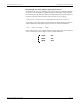
Pulser Module Setup Registers
Detailed Operation
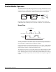
The figure below illustrates the operation of the Pulser module.
Each second, the Pulser module determines how many pulses it has received on its
Source input and outputs a like number of pulses to the specified hardware output
channel. Because the PulseWidth setup register limits the output pulse to a
minimum width, the Pulser module may not always be able to output a pulse for
every pulse it receives on its Source input. In these cases, the extra pulses are sent
to the hardware output channel in the next second. In cases where the Pulser
module can output the correct number of pulses, these pulses are spread evenly
throughout the second.
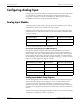
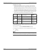
Setup Register Description
Output Mode
Specifies whether the output is a complete pulse (PULSE) or a change of state
transition (KYZ)
Pulse Width
Specifies the width (on-time) of the output pulse (e.g. how long an LED is lit or
relay is open)
Polarity
Defines the output polarity of the pulses if you have selected a complete pulse as
the Output Mode. It has no effect if you selected transition mode
Ports Defines the hardware port where the output appears
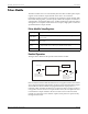
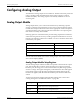
Pulser Module
Event Register
DEVICE
Source input
Pulse from another
module's Trigger or
Pulse output register.
Characteristics of
output pulse and
destination port defined
by setup registers.