SocketModem™ GSM/GPRS Embedded Data/Fax Wireless Modem MTSMC-G-F1 – Global GSM/GPRS Class 10, 900/1800 MHz MTSMC-G-F2 – Global GSM/GPRS Class 10, 850/1900 MHz Developer’s Guide
Global SocketModem GSM/GPRS Developer’s Guide MTSMC-G-F1 – GSM/GPRS Class 10, 900/1800 MHz MTSMC-G-F2 – GSM/GPRS Class 10, 850/1900 MHz PN S000297A, Version A Copyright This publication may not be reproduced, in whole or in part, without prior expressed written permission from Multi-Tech Systems, Inc. All rights reserved. Copyright © 2003, by Multi-Tech Systems, Inc. Multi-Tech Systems, Inc.
Table of Contents Table of Contents CHAPTER 1 – PRODUCT DESCRIPTION AND SPECIFICATIONS .......................................................... 4 PRODUCT DESCRIPTION ............................................................................................................................... 4 APPLICATIONS.............................................................................................................................................. 4 PRODUCT FEATURES........................................
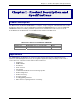
Chapter 1 – Product Description and Specifications Chapter 1 – Product Description and Specifications Product Description The Multi-Tech SocketModem GSM/GPRS is a complete, ready-to-integrate, embedded wireless modem. Designed for global use, it offers standards-based multi-band GSM/GPRS Class 10. The SocketModem GSM/GPRS is based on industry-standard open interfaces and utilizes the same form factor as the SocketModem, SocketModem IP, or SocketEthernet IP modules from Multi-Tech.
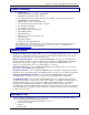
Chapter 1 – Product Description and Specifications Product Features · · · · · · · · · · · · · · · · GPRS Class 10 Dual-band 850/1900 or 900/1800 GSM/GPRS GSM Class 1 and Class 2 Group 3 FAX Short Message Services features including text and PDU, point to point, cell broadcast 14.4K GSM circuit switched data MMCX antenna connector and SIM socket Serial interface supports DTE speeds to 115.2K AT command compatible* V.
Chapter 1 – Product Description and Specifications Technical Specifications The SocketModem GSM/GPRS meets the following specifications: Fax Compatibility Weight Dimensions Power Requirements Operating Environment Storage Temperature Certifications Cleaning GSM Class 1 and Class 2 Group 3 Fax 1 oz (26 g) 3.1” w x 1.4” h x 0.5” d (8.0 cm x 3.5 cm x 1.
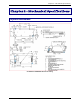
Chapter 2 – Mechanical Specifications Chapter 2 – Mechanical Specifications Physical Dimensions SocketModem GSM/GPRS Mechanical Drawing 7
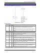
Chapter 2 – Mechanical Specifications Pin Configurations The SocketModem GSM/GPRS uses a 13-pin interface. SocketModem Pins - Top View Pin Descriptions Pin # 24 26, 41, 63 33 34 35 36 37 38 39 40 61 Signal I/O Description Name Type -RESET I/O Reset. This signal is used to force a reset procedure by providing low level during at least 500µs. This signal is considered an emergency reset only. A reset procedure is already driven by an internal hardware during the power-up sequence.
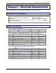
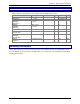
Chapter 3 – Electrical Characteristics Chapter 3 – Electrical Characteristics Electrical characteristics for the 5V Serial SocketModem are presented in this chapter. I/O Electrical Characteristics 5 Vdc Characteristics (TA = -20° C to 55° C; VDD = 5 V ± 0.25 V) Digital Inputs –DTR (40), –TXD (35), –RTS (33), –RESET (24) Digital Outputs –DCD (39), –CTS (38), –DSR (37), –RI (36), –RXD (34) Digital Input Capacitance VDDMAX = 5.25 V Input High Min 3.675 V Output High Min. 4 V Input Low Max 1.
Chapter 3 – Electrical Characteristics SIM Interface Electrical Characteristics SIM Interface Electrical Characteristics This information is repeated in the next chapter under the SIM Interface section. Parameter SIMDATA VIH SIMDATA VIL SIMRST, SIMDATA SIMCLK VOH SIMRST, SIMDATA SIMCLK VOL SIMVCC Output Voltage SIMCLK Rise/Fall Time SIMRST, SIMDATA Rise/Fall Time SIMCLK Frequency Conditions IIH = +/- 20mA IIL = 1 mA Source current = 20mA Min 0.7xSIMVCC Typ SIMVCC – 0.
Chapter 4 - SocketModem Interfaces Chapter 4 – SocketModem Interfaces This chapter describes the SocketModem interfaces. · Flashing LED · SIM Interface · RF Interface Flashing LED The flashing LED signal is used to indicate the working mode of the SocketModem.
Chapter 4 - SocketModem Interfaces RF Interface The impedance is 50 Ohms nominal. RF Connector The RF connector is MMCX standard type. An antenna can be directly connected through the mating connector or using a small adapter. RF Performances RF performances are compliant with the ETSI recommendation 05.05 and 11.10.
Chapter 5 – SocketModem Test Board Chapter 5 – SocketModem Test Board Serial Test/Demo Board Components 13
Chapter 5 – SocketModem Test Board Serial Test/Demo Board Block Diagram Block Diagram for the SocketModem GSM/GPRS 14
Chapter 6 – Application Considerations Chapter 6 – Application Considerations General Guidelines for the Use of the SocketModem Hardware and RF · · · Ground plane: Multi-Tech recommends having a common ground plane for analog, digital, and RF grounds. ESD protection on serial link. Possible spurious emission radiated by the application to the RF receiver in the receiver band The Antenna The antenna sub-system and integration in the application is a major issue.
Appendix A – Safety Precautions and Regulatory Standards Compliance Appendix A – Safety Precautions & Regulatory Standards Compliance Safety Precautions IMPORTANT! FOR THE EFFICIENT AND SAFE OPERATION OF YOUR GSM INTEGRATED MODEM READ THIS INFORMATION BEFORE USE. RF Safety General Your SocketModem is based on the GSM standard for cellular technology. The GSM standard is spread all over the world. It covers Europe, Asia, and some parts of America and Africa.
Appendix A – Safety Precautions and Regulatory Standards Compliance General Safety Driving Check the laws and the regulations regarding the use of cellular devices in the area where you have to drive as you must comply with these laws and regulations. When using your modem while driving, please give full attention to driving. Pull off the road and park before making or answering a call if driving conditions so require.
Appendix A – Safety Precautions and Regulatory Standards Compliance General Safety Standards THIS WIRELESS SOCKETMODEM COMPLIES WITH ALL APPLICABLE RF SAFETY STANDARDS.
Appendix A – Safety Precautions and Regulatory Standards Compliance Regulatory Standards Compliance GSM compliance The SocketModem is in compliance with reference regulations: TBR 19, TBR 20, TBR 31, TBR 32. CE Label The Wireless SocketModem is CE compliant, which implies that the modem is in conformity with the European Community directives and it bears the CE label.
Appendix B – Sources for Peripheral Devices Appendix B – Sources for Peripheral Devices GSM Antenna The integrated modem antenna connector is a MMCX connector. The MMCX connector incorporates a 'Snap On' latching action in order to make the connection easier with an excellent RF performance. An additional advantage is its small physical size, which is 50% of the standard MCX connector. This type of connector is suitable for the standard ranges of flexible and semi-rigid cables.
Appendix C – AT Commands Appendix C – AT Command List For comprehensive information about AT Commands, please read the AT Commands Reference Manual.
Appendix C – AT Commands AT Command List (continued) Security Commands +CPIN +CPIN2 +CPINC +CLCK +CPWD Enter PIN Enter PIN2 PIN Remaining Attempt Number Facility Lock Change Password Phone Book Commands +CPBS +CPBR +CPBF +CPBW +CPBP +CPBN +CNUM +WAIP Select Phone Book Memory Storage Read Phone Book Entries Find Phone Book Entries White Phone Book Entry Phone Book Phone Search Move Action in Phone Book Subscriber Number Avoid Phone Book Init Short Message Commands +CSMS +CNMA +CPMS +CMGF +CSAS +CRES +CSD
Appendix C – AT Commands AT Command List (continued) Supplementary Services Commands +CCFC +CLCK +CPWD +CCWA +CLIR +CLIP +COLP +CAOC +CACM +CAMM +CPUC +CHLD +CLCC +CSSN +CUSD +CCUG Call Forwarding Call Barring Modify SS Password Call Waiting Calling Line Identification Restriction Calling Line Identification Presentation Connected Line Identification Presentation Advice Of Charge Accumulated Call Meter Accumulated Call Meter Maximum Price Per Unit and Currency Table Call Related Supplementary Services List
Appendix C – AT Commands AT Command List (continued) V24 - V25 Commands +IPR +ICF +IFC &C &D &S O Q V Z &W &T E &F &V I Fixed DTE Rate DTE-DCE Character Framing DTE-DCE Local Flow Control Set DCD Signal Set DTR Signal Set DSR Signal Back to Online Mode Result Code Suppression DCE Response Format Default Configuration Save Configuration Auto-Tests Echo Restore Factory Settings Display Configuration Request Identification Information SIM Toolkit Commands +STSF +STIN +STGI +STCR +STGR SIM Toolkit Set Facili
Appendix D – Acronyms and Abbreviations Appendix D – Acronyms and Abbreviations ADC – Analog Digital Converter ASIC – Application Specific Integrated Circuit BCCH – Broadcast Control Channel CE – Communauté Européenne CLK – Clock CTS – Clear To send dB – decibel DCD – Data Carrier Detect DCE – Data Circuit Terminating Equipment DSR – Data Set Ready DTE – Data Terminal Equipment DTR – Data Terminated Ready EFR – Enhanced Full Rate EGSM – Extended GSM EMC – Electromagnetic Conformity EN – Enable ETSI – Europ
Index Index Advice Of Charge, 23 aircraft and safety, 17 analog, 25 antenna, 12, 15, 16, 20 antenna cable, 15 applications, 4 AT Commands, 21 AT commands documentation, 5, 6 blasting areas and safety, 17 Block Diagram, 14 Call Barring, 23 Call Forwarding, 23 Call Waiting, 23 CE, 19, 25 Cell Broadcast, 22 children and safety, 17 Cleaning the SocketModem, 15 Closed User Group, 23 Data Carrier Detect, 25 dB, 12, 25 DCS, 12 Developer’s Kit, 5 driving safety, 17 EFR, 25 Electrical characteristics, 9 electronic