CDMA Embedded Data/Fax/Voice Wireless Modem MTMMC-C Developer’s Guide
ModemModule Developer’s Guide MTMMC-C PN S000296B, Version B 10/17/03 Copyright This publication may not be reproduced, in whole or in part, without prior expressed written permission from Multi-Tech Systems, Inc. All rights reserved. Copyright © 2003, by Multi-Tech Systems, Inc. Multi-Tech Systems, Inc. makes no representations or warranties with respect to the contents hereof and specifically disclaims any implied warranties of merchantability or fitness for any particular purpose.
Table of Contents CHAPTER 1 – PRODUCT DESCRIPTION AND SPECIFICATIONS ................................................................4 INTRODUCTION ...........................................................................................................................................................4 APPLICATIONS ............................................................................................................................................................4 PRODUCT FEATURES ...................
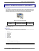
Chapter 1 – Product Description & Specification Chapter 1 – Product Description and Specifications Introduction The Multi-Tech ModemModule CDMA is a complete, ready-to-integrate, embedded data/fax/voice wireless modem packaged in a compact industrial chassis. Designed for global use, it offers standards-based multi-band CDMA2000 1x performance. This quick-to-market module allows developers to add wireless communication to products with a minimum of development time and expense.
Chapter 1 – Product Description & Specification Product Features · CDMA2000 1xRTT operation · CDMA IS-95-A, IS-95B · Dual-band 800/1900 CDMA · Class 2.0 Group 3 FAX · Board-to-board or board-to-cable mounting · Short Message Service features including SMS mobile originated, SMS mobile terminated, cell broadcast, Over the Air Activation (OTA), OTASP, OTAPA · Voice features include DTMF, telephony, OCELP 13K, echo cancellation · MMCX antenna connector · 14.
Chapter 1 – Product Description & Specification Developer’s Kit The ModemModule CDMA Developer’s Kit allows you to plug in the ModemModule and use it for testing, programming and evaluation. The kit includes one development board with RS-232 DB-25 connector, universal power supply, antenna and RS-232 cable. Technical Specifications Dimensions 2.5" w x 1.8" h x 0.5" d (6.4 cm x 4.6 cm x 1.
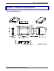
Chapter 2 – Mechanical Specifications Chapter 2 – Mechanical Specifications Mechanical Dimensions ModemModule Dimensions Wireless ModemModule MTMMC-C Developer's Guide 7
Chapter 3 – Electrical Characteristics Chapter 3 – Electrical Characteristics Introduction This chapter describes the ModemModule’s electrical interfaces.
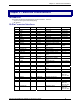
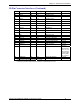
Chapter 3 – Electrical Characteristics 50-Pin Connector Interfaces (Continued) Pin # Name I/O I/O Type Description 31 32 33 COL3 COL4 COL1 I/O I/O I/O 1X 1X 1X Keypad column Keypad column Keypad column 34 COL2 I/O 1X Keypad column 35 ROW4 I/O 1X Keypad row 36 COL0 I/O 1X Keypad column 37 ROW2 I/O 1X Keypad row 38 ROW3 I/O 1X Keypad row 39 ROW0 I/O 1X Keypad row 40 ROW1 I/O 1X Keypad row 41 42 43 44 45 46 47 NC SPI_EN SPI_IO SPI_CLK SIMCLK SIMRST SIMVCC O I/O O
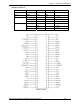
Chapter 3 – Electrical Characteristics Operating Conditions Parameter I/O Type Min Max Vinput low CMOS -0.5V 0.8V Vinput high CMOS 2.1V 3.0V Voutput low 1X 0.2V IOL = -1mA 2X 0.2V IOL = -2mA 3X 0.2V IOL = -3mA Voutput high Condition 1X 2.6V IOH = 1mA 2X 2.6V IOH = 2mA 3X 2.
Chapter 3 – Electrical Characteristics 50 49 2 1 Pin Numbering – Bottom View Power Consumption Operating Mode Band CDMA RXTX Full Power CMA RXTX Average Power Cellular PCS Cellular PCS Cellular PCS CDMA Standby Average (mA) 615 770 340 445 20 20 Handling Precautions All devices must be handled with certain precautions to avoid damage due to the accumulation of static charge.
Chapter 4 – Interfaces Chapter 4 – Interfaces This chapter describes the ModemModule interfaces. · External antenna · RF Interface RF Interface The impedance is 50 Ohms nominal. RF Connector The RF connector is MMCX standard type. An antenna can be directly connected through the mating connector or using a small adapter. Transmitter Specifications Transmitter performance test specification is CDMA2000 mobile station minimum requirement standard, 3GPP2 TSG C0011-A.
Chapter 4 – Interfaces Receiver Specifications Receiver performance test specification is CDMA2000 mobile station minimum requirement standard, 3GPP2 TSG C.S0011-A. Operating Frequency Modulation Conversion Method Oscillation Method Receiver Sensitivity Single Tone Desensitization IMD Conducted Spurious Emission RX Band TX Band Other Frequency 869MHz ~ 894MHz (Cellular Band) 1930MHz ~ 1990MHz (PCS Band) QPSK Heterodyne VCTCXO & PLL Synthesizer -104dBm @ FER 0.
Chapter 5 – Test Board Chapter 5 – Test Board Wireless ModemModule MTMMC-C Developer's Guide 14
Chapter 5 – Test Board Wireless ModemModule MTMMC-C Developer's Guide 15
Chapter 5 – Test Board Wireless ModemModule MTMMC-C Developer's Guide 16
Chapter 5 – Test Board Test Board Block Diagram Block Diagram Wireless ModemModule MTMMC-C Developer's Guide 17
Chapter 6 – Application Considerations Chapter 6 – Application Considerations General Guidelines for the Use of the ModemModule Hardware and RF · · · · · Ground plane: Multi-Tech recommends having a common ground plane for analog, digital and RF grounds. Bias of the Microphone inputs must be properly adjusted when using audio connectors (mic + speaker) 1.
Chapter 6 – Application Considerations Getting Started Minimum Hardware Interface Required To Get Started At a minimum, it is necessary to connect the following signals too properly operate the ModemModule: Pin Number Name Description 1 GND Ground 2 GND Ground 3 +5V Power Supply 4 +5V Power Supply 6 GND Ground 13 CT106/CTS Clear to Send 15 ON/OFF Power On/Off * 21 GND Ground 24 GND Ground 25 CT103/TX Transmit 28 CT104/RX Receive 30 CT105/RTS Request to Send * Connect
Appendix A – Safety Precautions & Regulatory Standards compliance Appendix A – Safety Precautions & Regulatory Standards Compliance Safety Precautions IMPORTANT! FOR THE EFFICIENT AND SAFE OPERATION OF YOUR CDMA INTEGRATED MODEM READ THIS INFORMATION BEFORE USE. RF Safety General Your ModemModule is based on the CDMA standard for cellular technology. Your modem is actually a low power radio transmitter and receiver. It sends out and receives radio frequency energy.
Appendix A – Safety Precautions & Regulatory Standards compliance General Safety Driving Check the laws and the regulations regarding the use of cellular devices in the area where you have to drive as you always have to comply with them. When using your modem while driving, please: give full attention to driving, pull off the road and park before making or answering a call if driving conditions so require.
Appendix A – Safety Precautions & Regulatory Standards compliance Safety Standards THIS WIRELESS MODEMMODULE COMPLIES WITH ALL APPLICABLE RF SAFETY STANDARDS.
Appendix B – Sourcing Guide for Connectors/Peripherals Appendix B – Sourcing Guide for Connectors and Peripheral Devices CDMA Antenna The integrated modem antenna connector is a MMCX connector. The MMCX connector incorporates a 'Snap On' latching action in order to make the connection easier with an excellent RF performance. An additional advantage is its small physical size, which is 50% of the standard MCX connector.
Appendix D – Acronyms and Abbreviations Appendix C – AT Command List For comprehensive information about AT Commands, please read the AT Command Manual.
Appendix D – Acronyms and Abbreviations AT Command List (cont’d) Call Control Commands D Dial command H Hang-up Command A Answer a Call +CEER Extended Error Report +VTD, +VTS DTMF Signals ATDL Redial Last Telephone Number AT%Dn Automatic Dialing (or SMS send) with DTR ATSO Automatic Answer +CICB Incoming Call Bearer +VGR, +VGT Gain Control +CMUT Microphone Mute Control +SPEAKER Speaker and Microphone Selection +ECHO Echo Cancellation +SIDET Side Tone Modification +VIP Initialize
Appendix D – Acronyms and Abbreviations AT Command List (cont’d) Short Message Commands +CSMS +CNMA +CPMS +CMGF +CSAS +CRES +CSDH +CNMI +CMGR +CMGL +CMGS +CMGW +CMSS +CSMP +CMGD +CSCA +CSCB +WCBM +WMSC +WMGO Select Message Service New Message Acknowledgement Preferred Message Storage Preferred Message Format Save Settings Restore Settings Show Text Mode parameters New Message Indication Read Message List Message Send Message Write Message to Memory Send Message from Storage Set Text Mode Parameters Delete
Appendix D – Acronyms and Abbreviations AT Command List (cont’d) Fax Commands +FTM +FRM +FTH +FRH +FTS +FRS Transmit Speed Receive Speed HDLC Transmit Speed HDLC Receive Speed Stop Transmission and Wait Receive Silence Fax Class 2 Commands +FDT +FDR +FET +FPTS +FK +FBOR +FBUF +FCQ +FCR +FDIS +FDCC +FLID +FPHCTO Transmit Data Receive Data Transmit Page Punctuation Page Transfer Status Parameters Terminate Session Page Transfer Bit Order Buffer Size Report Copy Quality Checking Capability to Receive Curren
Appendix D – Acronyms and Abbreviations AT Command List (cont’d) Specific AT Commands +CCED Cell Environment Description +CCED Automatic RxLev Indication +WIND General Indications +ADC Analog Digital Converters Measurements +CMER Mobile Equipment Event Reporting +WLPR Read Language Preference +WLPW Write Language Preference +WIOR Read GPIO Value +WIOW Write GPIO Value +WAC Abort Command +WTONE Play Tone +WDTMF Play DTMF Tone +WDWL Multi-Tech Downloading +WVR Multi-Tech Voice Rate
Appendix D – Acronyms and Abbreviations Appendix D – Acronyms and Abbreviations ADC : Analog Digital Converter ASIC : Application Specific Integrated Circuit BCCH : Broadcast Control Channel CE : Communauté Européenne CLK : Clock CTS : Clear To send dB : decibel DCD : Data Carrier Detect DCE : Data Circuit Terminating Equipment DSR : Data Set Ready DTE : Data Terminal Equipment DTR : Data Terminated Ready EFR : Enhanced Full Rate EMC : Electromagnetic Conformity EN : Enable ETSI : European Telecommunicatio
Index Index 1X ..................................................................9, 10, 11 2X ..................................................................9, 10, 11 3X ......................................................................10, 11 Advice Of Charge....................................................25 analog ................................................................17, 28 antenna...................................................17, 19, 20, 21 antenna cable .........................