Universal Socket Connectivity Embedded Device Networking Solutions Hardware Guide for Developers
Copyright and Technical Support Universal Socket Connectivity Hardware Guide for Developers for HDSPA Approval Rev. A, 08/267/07 Copyright This publication may not be reproduced, in whole or in part, without prior expressed written permission from MultiTech Systems, Inc. All rights reserved. Copyright © 2004-7 by Multi-Tech Systems, Inc. Multi-Tech Systems, Inc.
Chapter 1 – Universal Socket Connectivity Chapter 1 - Universal Socket Connectivity Multi-Tech Embedded Solutions Multi-Tech’s embedded device networking solutions instantly add communication ability to your existing or new product with minimal engineering effort giving you an edge on your competition while accelerating your time-tomarket.
Chapter 1 – Universal Socket Connectivity Universal Developer Kit Contents All products covered in this document can be evaluated using the MTSMI-UDK (Universal Developer Kit).
Chapter 1 – Universal Socket Connectivity Design Considerations Noise Suppression Design Considerations Engineering noise-suppression practices must be adhered to when designing a printed circuit board (PCB) containing the SocketModem module. Suppression of noise is essential to the proper operation and performance of the modem itself and for surrounding equipment.
Chapter 1 – Universal Socket Connectivity Electromagnetic Interference (EMI) Considerations The following guidelines are offered to specifically help minimize EMI generation. Some of these guidelines are the same as, or similar to, the general guidelines but are mentioned again to reinforce their importance. In order to minimize the contribution of the SocketModem-based design to EMI, the designer must understand the major sources of EMI and how to reduce them to acceptable levels. 1.
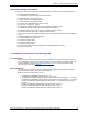
Chapter 1 – Universal Socket Connectivity Mechanicals and Schematics Mechanical Dimensions in Inches Note: This tooling hole is not on all models. 64 63 62 61 60 59 58 57 56 55 54 1 2 3 4 5 6 7 8 9 10 11 53 12 52 13 51 14 50 15 49 16 48 17 47 18 46 19 45 20 44 21 43 22 42 23 41 24 40 25 39 26 38 27 37 28 36 29 35 30 34 31 33 32 Dimensions Are Shown in Inches Multi-Tech Systems, Inc.
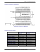
Chapter 1 – Universal Socket Connectivity Mechanical Dimensions in Millimeters Dimensions Are Shown in Millimeters Maximum Component Height Product Measurement from top of board to highest topside component Measurement from bottom of board to lowest bottom-side component SocketModem – MT5600SMI SocketModem – MT5656SMI SocketModem – MT5634SMI SocketModem – MT9234SMI SocketModem – MT2492SMI SocketModem – MT2456SMI SocketModem IP – MT2456SMI-IP SocketModem IP – MT5656SMI-IP SocketEthernet IP – MTXCSEM So
Chapter 2 – SocketModem HSDPA Antenna System for Embedded GSM and CDMA Modems The antenna system for use with Multi-Tech GSM or CDMA modems includes a coax cable to interface between UFL or MMCX connection on the modem and the antenna. RF Specifications GSM/EGSM RF Specifications GSM 850 Frequency RX Frequency TX RF Power Stand EGSM 900 GSM 1800 GSM 1900 869 to 894 MHz 925 to 960 MHz 1805 to 1880 MHz 1930 to 1990 MHz 824 to 849 MHz 880 to 915 MHz 1710 to 1785 MHz 1850 to 1910 MHz 2W at 12.
Chapter 2 – SocketModem HSDPA Connector An antenna with an SMA connector may be directly connected to a SocketModem GPRS/CDMA through a mating MMCX to SMA adapter. MMCX / SMA Connector Available from Amphenol Amphenol http://www.amphenol.com/ Order No: 908-31100 Antenna GSM/EGSM Antenna Requirements/Specifications Frequency Range: Impedance: VSWR: Typical Radiated Gain: Radiation: Polarization: Wave: 2.4 to 2.5 GHz 50 ohm <2.
Chapter 2 – SocketModem HSDPA Safety Notices and Warnings Note to OEMs: The following safety statements may be used in the documentation of your final product applications. Telecom Safety Warning 1. 2. 3. 4. 5. 6. 7. 8. 9. Never install telephone wiring during a lightning storm. Never install a telephone jack in wet locations unless the jack is specifically designed for wet locations. This product is to be used with UL and cUL listed computers.
Chapter 2 – SocketModem HSDPA Vehicle Safety • Do not use your MultiModem while driving. • Respect national regulations on the use of cellular telephones in vehicles. Road safety always comes first. • If incorrectly installed in a vehicle, the operation of Wireless MultiModem telephone could interfere with the correct functioning of vehicle electronics. To avoid such problems, be sure that qualified personnel have performed the installation.
Chapter 2 – SocketModem HSDPA Waste Electrical and Electronic Equipment Statement Note to OEMs: The statement is included for your information and may be used in the documentation of your final product applications. WEEE Directive The WEEE directive places an obligation on EU-based manufacturers, distributors, retailers, and importers to takeback electronics products at the end of their useful life.
Chapter 2 – SocketModem HSDPA Restriction of the Use of Hazardous Substances (RoHS) Multi-Tech Systems, Inc. Certificate of Compliance 2002/95/EC Multi-Tech Systems Inc. confirms that MTxxxxSMI, MTSMC-G-F1, MTxxxxSEM, MTIFM, and MTxxxSWM now comply with the chemical concentration limitations set forth in the directive 2002/95/EC of the European Parliament (Restriction Of the use of certain Hazardous Substances in electrical and electronic equipment - RoHS) These Multi-Tech Systems, Inc.
Chapter 2 – SocketModem HSDPA Chapter 2 – SocketModem HSDPA Introduction The Multi-Tech SocketModem HSDPA embedded wireless modem delivers some of the fastest cellular data speeds by utilizing HSDPA technology. It allows users to connect to the Internet and send and receive data faster than possible with an ordinary GSM/GPRS network making it ideal for highly data-intensive applications.
Chapter 2 – SocketModem HSDPA Technical Specifications Category Standards: GSM Class GSM / GPRS / EGPRS Data Transfer UMTS Data Rate (Release 99, June 2004, W-CDMA FDD standard) Bandwidth Connectors Operating Voltage (Power Supply) Output power (according to Release 99) Description Small MS GPRS • Multislot Class 10 • Full PBCCH support • Mobile Station Class B • Coding Scheme 1 – 4 EGPRS • EDGE E2 power class for 8 PSK • Downlink coding schemes – CS 1-4, MCS 1-9 • Uplink coding schemes – CS 1-4, MCS 1-
Chapter 2 – SocketModem HSDPA Warranty Intelligent Features 2 years SMS – Text & PDU, Point-to-Point, cell broadcast AT Command Compatible Voice features include Half Rate (HR), Full Rate (FR), Enhanced Full Rate (EFR), Adaptive multi rate (AMR), as well as hands free echo cancellation, and noise reduction Embedded TCP/IP protocol stack brings Internet connectivity Audio Audio speech codecs • GSM: AMR, EFR, FR, HR • 3GPP: AMR-WB • 3GPP2: EVRC, EVRC-B (4GV-WB/NB) • Diverse: G.
Chapter 2 – SocketModem HSDPA HSPDA Electrical Characteristics I/O Electrical Characteristics 5VDC Characteristics (VDD = 5V ± 0.25V) VDDMAX = 5.25V Digital Inputs –DTR (40), –TXD (35), –RTS (33) –RESET Digital Outputs –DCD (39), –CTS (38), –DSR (37), –RI (36), –RXD (34) Digital Input Capacitance Input High Min 2.0V Input High Min 2.6V Output High Min 4V Input Low Max 0.8V Input Low Max 1.0V Output Low Max 0.
Chapter 2 – SocketModem HSDPA Application Notes Radio Characteristics Frequency RX Frequency TX RF Power Stand GSM 850 869 to 894 MHz 824 to 849 MHz 2W at 12.5% duty cycle Impedance VSWR Typical Radiated Gain EGSM 900 GSM 1800 925 to 960 MHz 1805 to 1880 MHz 880 to 915 MHz 1710 to 1785 MHz 2W at 12.5% duty 1W at 12.5% duty cycle cycle 50 ohms <2 0 dBi on azimuth plane GSM 1900 1930 to 1990 MHz 1850 to 1910 MHz 1W at 12.
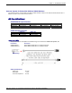
Chapter 2 – SocketModem HSDPA Baud Rate Switches on the HSDPA SocketModem MTSMC-H SocketModem Baud Rate dip switch settings Switch Bank ● 1 ● 2 ● 3 ● 4 920K ● 2 ● 3 ● 4 460K ● 3 ● 4 230K ● 3 ● 4 115K ● 4 57.6K ● 4 38.4K ● 4 19.2K ● 4 9.6K ● 1 ● ● 1 2 ● ● 1 2 ● 1 ● 2 ● ● 1 3 ● ● 2 3 ● ● ● 1 2 3 ● ● ● 1 2 3 Multi-Tech Systems, Inc.
Chapter 2 – SocketModem HSDPA Operating Modes The table below briefly summarizes the various operating modes. Mode Normal operation Function GSM / GPRS / UMTS / HSDPA SLEEP GSM IDLE Power saving mode set automatically when no call is in progress and the USB connection is suspended by host or not present. Software is active. Once registered to the GSM network, paging with BTS is carried out in order to achieve synchrony with the GSM network. The repetition rate depends on the parameter BSPA_Multiframe.
Chapter 2 – SocketModem HSDPA Turn off the Module Using AT Command The best and safest approach to powering down is to issue the AT^SMSO command. This procedure lets the module log off from the network and allows the software to enter into a secure state and safe data before disconnecting the power supply. The mode is referred to as Power-down mode. In this mode, only the RTC stays active. After sending AT^SMSO do not enter any other AT commands.