Data/Voice/Fax Concentrator Desktop Models: DT101, DT102, DT101/xx, DT102/xx Rack-Mount Models: DT101R, DT102R, DT101R/xx, DT102R/xx Owner’s Manual
Owner’s Manual 82052704 Revision E DataTalker™ Series Desktop Models: DT101, DT101/xx, DT102, DT102/xx Rack-Mount Models: DT101R, DT101R/xx, DT102R, DT102R/xx This publication may not be reproduced, in whole or in part, without prior expressed written permission from Multi-Tech Systems, Inc. All rights reserved. Copyright © 1997, by Multi-Tech Systems, Inc. Multi-Tech Systems, Inc.
Contents Chapter 1 - Introduction and Description 1.1 1.2 1.3 1.4 Introduction .................................................................................................................................... 8 About This Manual ......................................................................................................................... 8 Product Description .....................................................................................................................
Chapter 4 - Unpacking and Configuration 4.1 4.2 4.3 4.4 4.5 4.6 4.7 Introduction .................................................................................................................................. Unpacking ................................................................................................................................... Configuration Summary ...............................................................................................................
Appendixes Appendix A - ASCII Conversion Chart ..................................................................................................... 118 Appendix B - RS-232C Interface Specification ........................................................................................ 119 Appendix C - Cabling Diagrams ............................................................................................................. 120 Appendix D - Flow Control Background ........................................
Chapter 1 - Introduction and Description
DataTalker Owner’s Manual 1.1 Introduction Congratulations! Your new Multi-Tech DataTalker™ is one of the finest data/voice/fax concentrators on the market today. The DataTalker optimizes wide area network (WAN) links by simultaneously transmitting voice and/or fax with LAN or computer data over a single phone line, digital service, or ISDN service.
Chapter 1 - Introduction and Description Chapter 4 - Unpacking and Configuration This chapter describes the contents of the shipping container; provides a customizeable configuration summary; discusses configuration considerations for the data port, voice/fax channel, and the composite link; and provides a detailed configuration procedure.
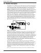
DataTalker Owner’s Manual 1.3 Product Description The DataTalker series of multiplexers has a single synchronous or asynchronous data channel, a command port, one or two voice/fax channels, and a single synchronous composite link with an internal data service unit (DSU), modem, ISDN terminal adapter, or an external synchronous link device.
Chapter 1 - Introduction and Description communications software to the DATA/COMMAND connector on the back panel and configure the data channel for the type of data that is going to be transferred. For example, if an asynchronous device is going to be connected to the data channel, you must set the speed of the channel, the word length, the number of stop bits, whether or not you are going to have parity checking, the flow control type, and other aspects of asynchronous data.
DataTalker Owner’s Manual 1.4 System Features 1.4.1 Voice/Fax The voice/fax feature of the DataTalker allows you to establish voice or fax traffic on top of your normal data communications over a composite link, saving the expense of extra communications lines. The DataTalker provides three types of telephone circuits (FXS, FXO, and E&M) that allow a telephone, a fax machine, a PBX station card, or a PBX E&M trunk to be directly connected to it.
Chapter 1 - Introduction and Description 1.4.6 Diagnostics Diagnostics in a network are of considerable importance. That is why the DataTalker is equipped with several diagnostic modes that will test every aspect of the network. The diagnostics include easy-to-execute tests for the data channel, voice/fax channel, composite link, and various components of the DataTalker unit itself.
DataTalker Owner’s Manual 1.5 FCC Regulations for Telephone Line Interconnection 1. This equipment complies with Part 68 of the FCC rules. On the outside surface of this equipment is a label that contains, among other information, the FCC registration number and ringer equivalence number (REN). If requested, this information must be provided to the telephone company. 2. As indicated below the suitable jack (USOC connecting arrangement) for this equipment is shown.
Chapter 1 - Introduction and Description 1.6 Canadian Limitations Notice Notice: The Canadian Department of Communications label identifies certificated equipment. This certification means that the equipment meets certain telecommunications network protective, operational and safety requirements. The department does not guarantee the equipment will operate to the user’s satisfaction.
DataTalker Owner’s Manual 1.7 Specifications 1.7.1 Number of Channels One Maximum Speed 115,200 bps Channel Speed All standard speeds from 300 bps to 115,200 bps Data Format 5, 6, 7, or 8 data bits, with 1, 1.5, or 2 stop bits Parity Odd, even, or none Local Echo On or off selectable Flow Control XON/XOFF, CTS, or HP ENQ/ACK selectable Pacing On or off selectable, RTS on/off, or XON/XOFF Interface RS-232D/ITU-T V.24; DB-25 female connector 1.7.
Chapter 1 - Introduction and Description 1.7.5 Internal Modem Modulation ITU-T V.34; AT&T V.32 terbo; ITU-T V.32bis, V.32, V.22bis, V.22; Bell 212A and 103 (North America) or V.23 and V.21 (international) Speeds 300 bps to 33.
DataTalker Owner’s Manual 1.7.9 Electrical/Physical Desktop Models: Power Supply Input 100 to 250 VAC Power Supply Output +5v@5A, +12v@1A, -12v@0.5A Power Consumption 20 watts Dimensions 2.3" high x 9" wide x 12.8" deep 5.7 cm high x 22.9 cm wide x 32.7 cm deep Weight 7 pounds (3.2 kg) Rack-mount Models: 18 Power Supply Input 100 to 250 VAC Frequency 47 to 63 Hz Power Consumption 20 watts Dimensions 2.00" high x 9. 98" wide x 12.75" deep 5.1 cm high x 25.2 cm wide x 32.
Chapter 2 - Configuration
DataTalker Owner’s Manual 2.1 Introduction The Multi-Tech DataTalker is available in both desktop (DT10x) and rack-mount (DT10xR) versions. The desktop version is designed for home office applications. It is mounted in a horizontal cabinet and has an external power supply, a power switch, an originate switch, and a switch that allows you to use it also as a stand-alone modem or terminal adapter. The rack-mount version is designed for main office applications.
Chapter 2 - Configuration 2.2 Configuration 1 - Dial-Up Link Configuration 1 is a dial-up link using a pair of DataTalkers to provide data communications between a home office PC and the main office host computer and telephone services through the main office telephone system. The data and telephone services are provided using a single line between the home office and the main office.
DataTalker Owner’s Manual When you established communication, the Main Menu appeared. From the Main Menu you can configure the unit, display statistics, reset various functions within the DataTalker, and run diagnostic tests: Main Menu 1 - Configurations 2 - Statistics 3 - Reset Options 4 - Diagnostics 5 - Exit Command Mode 6 - QUICK SETUP Selection : _ To configure the DataTalker, enter 1 and press ENTER. The Configurations menu is displayed.
Chapter 2 - Configuration Enter S and press ENTER to store all configurations for the main office. Set up the home office unit the same way, except that you should switch the local and remote interface types (FXS for the local interface and FXO for the remote interface). After you select the home office options, enter S to store all configurations. Enter P to return to the Configurations menu. At the Configurations menu, select option 3, Composite Link Configuration.
DataTalker Owner’s Manual To connect the home office DataTalker to its PC, connect an RS232C cable between the DATA/ COMMAND connector on the DataTalker and an async port on the PC (typically, COM1 or COM2). Place DIP switch position 3 on the side of the DataTalker in the OPEN (up) position to enable the data channel. To connect your home telephone to the DataTalker, remove the telephone cable from the wall jack and connect it to the VOICE/FAX CHANNEL 1 FXS connector on the DataTalker.
Chapter 2 - Configuration 2.3 Configuration 2 - MMH900 Series with Voice/Fax Configuration 2 adds voice capability to an existing data-only network using the same composite link. The example shown in Figure 2-2 had an existing data-only network consisting of a MultiMux MMH904C multiplexer connected to a host computer at the local site and a second MMH904C connected to terminals and/or PCs and a shared printer at the remote site.
DataTalker Owner’s Manual A series of configuration menus provides simple and complete configuration information for each aspect of the DataTalker. From the Main Menu, you can access menus to configure the unit, display statistics, reset various functions within the DataTalker, and run diagnostic tests: Main Menu 1 - Configurations 2 - Statistics 3 - Reset Options 4 - Diagnostics 5 - Exit Command Mode 6 - QUICK SETUP Selection : _ To go to the Configurations menu, enter 1 and press ENTER.
Chapter 2 - Configuration The data port in this configuration will be set up for synchronous operation. To configure the data port for sync operation, enter 1 (Aysnc/Sync) option and change the default Async to Sync. The data port configuration menu displays the sync parameters.
DataTalker Owner’s Manual 2.4 Configuration 3 - LAN to LAN Configuration 3 is an example of a pair of DataTalkers providing the link between two LANs with the added benefit of voice or fax traffic over the same composite link. Bridging the LANs over a single high speed composite link expands the capacity of each LAN. The LAN bridge on each LAN is provided by a router/bridge with a synchronous interface connected to the DataTalker’s data channel.
Chapter 2 - Configuration To configure the DataTalker, enter 1 and press ENTER. The Configurations menu is displayed. From this menu you can configure the data port, voice/fax channel(s), or the composite link.
DataTalker Owner’s Manual Data Port Configuration 1 - Async/Sync: 2 - Speed: 3 - Clocking: 4 - Idle Condition: 5 - NRZ/NRZI Encoding: 6 - CRC Preset: 7 - Inter-frame Timer: S - Store All Configuations M - Main Menu P - Previous Menu Selection : _ Sync 19200 Internal Flags NRZ All 1s Off Press P to return to the Data Port Configuration menu, enter S to store all configurations, and then press P again to return to the previous menu. At the Configurations menu, enter 2 and press ENTER.
Chapter 2 - Configuration The DataTalker knows the type of link device being used by the way a DIP switch is set or by detecting a device installed on the main PC board.
DataTalker Owner’s Manual 2.5 Configuration 4 - PBX to PBX Configuration 4 is a data/voice/fax configuration that uses two DataTalkers to link two PBXs. Using a single ISDN composite link, they connect a minicomputer and a PBX E&M trunk at the local site to a remote PC on the data part of the network and a second PBX E&M trunk on the voice/fax channel. The configuration is shown in Figure 2-4.
Chapter 2 - Configuration The Configurations menu is displayed. From this menu you can configure the data port, voice/fax channel(s), or the composite link. You can also select various factory defaults and store your current configuration.
DataTalker Owner’s Manual Composite Link Settings - Internal TA 1 2 3 S M P - On-Line XMT Rate: Configure TA DOD/DOI: Store All Configurations Main Menu Previous Menu 128000 Off Selection : _ The terminal adapter menu displays the transmit rate and option 2 allows you to configure the terminal adapter. Use option 2 (Configure TA) to access the terminal adapter’s built-in configuration menus (refer to the ISDN Terminal Adapter Owner’s Manual for details).
Chapter 3 - Front and Rear Panel Descriptions
DataTalker Owner’s Manual 3.1 Introduction This chapter describes the DataTalker front and back panels and switches. The front panel contains LED indicators for the data channel device, voice/fax channels, and the composite link. It also contains one or two switches, depending on whether it is a desktop or rack version. The back panel contains connectors for the data/command device, internal and external composite link devices, and the voice/fax channel devices. The desktop version also has a power switch.
Chapter 3 - Front and Rear Panel Descriptions Voice/Fax Channels FXS (Foreign Exchange Station) This indicator lights when the voice/fax channel is configured for FXS operation. FXO (Foreign Exchange Office) This indicator lights when the voice/fax channel is configured for FXO operation. E&M (E&M Operation) This indicator lights when the voice/fax channel is configured for E&M operation (voice/fax channel 1 only). FAX (Fax) This indicator lights when there is fax traffic on the voice/fax channel.
DataTalker Owner’s Manual 28.8/56 (28.8K bps/56K bps) This composite link speed indicator displays the baud rate of the internal modem (28.8) or DSU (56K). The type of composite link device is indicated by which of the EXT, MDM, DSU, or TA indicators lights. This indicator lights steadily when a DSU is installed. It has three states when an internal MMH2834 modem is installed (ON, flashing seven or eight times per second). When the LED is ON solid, it indicates a link speed of 33.6K bps.
Chapter 3 - Front and Rear Panel Descriptions 3.3 Connectors The cable connections for the DataTalker are made at the back panel. Refer to Chapter 5 for cabling installation procedures. Refer to Appendix C for cabling diagrams. The DataTalker back panel is shown in Figure 3-2. Frame Ground VOICE/FAX CHANNEL 2 DATA/COMMAND DIAL-UP LEASED DIGITAL MODEM DSU/TA INTERNAL COMPOSITE E&M FXO FXS VOICE/FAX CHANNEL 1 GND RS232C/V.35 EXTERNAL COMPOSITE POWER Power Switch Figure 3-2.
DataTalker Owner’s Manual 3.3.7 VOICE/FAX CHANNEL 1 E&M Connector Use the E&M connector to connect the DataTalker to the E&M connector on an analog PBX trunk when linking two PBXs together. The E&M connector is an RJ-48 jack. This connector is available on voice/fax channel 1 only. 3.3.8 DSU/TA DIGITAL Connector Use the DSU/TA Digital connector to connect the DataTalker to a DDS or dedicated network line when an internal DSU is installed, or to an ISDN line when the ISDN terminal adapter is installed.
Chapter 3 - Front and Rear Panel Descriptions 3.4 Switches and Shunts DataTalker switches include one or two switches on the front panel, a power switch on the back panel of the desktop version, and a DIP switch and shunt on the main printed circuit board (Figures 3-3 and 3-4). Power Switch RS-232 Shunt 1 V.35 Shunt 2 3 4 5 6 DIP Switch Originate Switch 101-MDM/TA Switch Figure 3-3. Switches and Shunts (Desktop Version) Power Connector MultiMux 101 1 V.
DataTalker Owner’s Manual 3.4.3 DIP Switch The eight-position DIP switch is accessible through a cutout in the left side of the DataTalker series enclosure; its location is shown in Figures 3-3 and 3-4.
Chapter 4 - Unpacking and Configuration
DataTalker Owner’s Manual 4.1 Introduction This chapter describes what to expect in your DataTalker shipping box, then describes how to configure the DataTalker. It provides a helpful configuration summary to give you a snapshot of how your unit is set up; summarizes options you should consider when configuring the data channel, router port, voice/fax channel, and composite link; and then guides you step by step through the initial configuration procedure. 4.
Chapter 4 - Unpacking and Configuration 4.3 Configuration Summary The following chart shows possible configurations for your DataTalker. Use it as a snapshot of how your unit is set up. Circle the parameters that apply to your unit. For example, if your unit has the data channel set up for asynchronous communications, circle “Async.
DataTalker Owner’s Manual 4.5 Voice/Fax Channel Configuration Considerations When configuring the voice/fax channels on your DataTalker, the first question you should ask yourself is what the voice/fax port is connected to. The possibilities are an in-plant telephone switch, or PBX, (Private Branch eXchange); a PBX E&M trunk; or a telephone. If the voice/fax channel is being connected to a PBX, use the FXO connector. If it is being connected to a telephone, use the FXS connector.
Chapter 4 - Unpacking and Configuration 4.6 Composite Link Configuration Considerations The composite link configuration depends on the type of device used as the composite link device. The DataTalker knows the type of composite link device being used by the setting of a DIP switch and the sensing of conditions within the unit. In most cases you can use the default composite link configuration.
DataTalker Owner’s Manual 4.7 Configuration Procedure Table 4-1. Configuration Procedure Step Procedure 1 Review the configuration considerations for the data port, the voice/fax channel, and the composite link in the previous sections. 2 Place DIP switch position 3 in the down (closed) position to enable the command port. DATA/COMMAND DIAL-UP LEASED DIGITAL E&M MODEM DSU/TA INTERNAL COMPOSITE 3 FXO FXS VOICE/FAX CHANNEL 1 GND RS232C/V.
Chapter 4 - Unpacking and Configuration 6 Apply power to the terminal or PC. Run your PC communications software in terminal mode. Press the ENTER key twice to establish communications with the DataTalker; the Main Menu then appears: Main Menu 1 - Configurations 2 - Statistics 3 - Reset Options 4 - Diagnostics 5 - Exit Command Mode 6 - QUICK SETUP Selection : _ 7 To configure the DataTalker, enter number 1 and press ENTER.
DataTalker Owner’s Manual 9 Configure the data port to meet the conditions of your installation by selecting option numbers from the menus. Refer to Chapter 6 for a description of the Data Port Configuration menu options. For example, if you are setting up the data port as a sync data channel, enter number 1 and press ENTER.
Chapter 4 - Unpacking and Configuration 12 Configure voice/fax channel 1 to meet the conditions of your installation by selecting option numbers from the menus. • Accept the defaults for the first five options. • Select the local interface type (option 6). • Select the remote interface type (option 11). The remote interface option does not change the interface type on the remote unit; it only tells the local DataTalker how the remote unit is configured.
DataTalker Owner’s Manual • Configure the internal MMH2834 modem to meet the conditions of your installation by selecting option numbers from the menus. • If you are setting up DTR dialing, select option 1, Enter AT Commands to 2834.
Chapter 4 - Unpacking and Configuration To verify and/or change the terminal adapter’s configuration, select option 2, wait 5 seconds, and enter AT!V to access the terminal adapter’s configuration menu. Refer to the ISDN Terminal Adapter Owner’s Manual for configuration commands. To exit the terminal adapter’s configuration menu, enter CTRL+X; then, to return to the DataTalker’s Composite Link Settings - Internal TA menu, press ENTER, Q.
DataTalker Owner’s Manual 54
Chapter 5 - Installation
DataTalker Owner’s Manual 5.1 Introduction This chapter describes how to connect the DataTalker to your system (Table 5-1) and how to move the RS232/V.35 shunt when a V.35 interface is used (Table 5-2). Then it describes how to power on your DataTalker, check that the unit is cabled and configured correctly, and what to do if you run into problems. 5.2 Cabling Connecting the DataTalker to your system requires two to four cables, depending on how you intend to use the DataTalker.
Chapter 5 - Installation MMH2834 Modem, Leased Line Connect the RJ-11 phone cable supplied with the DataTalker from the internal modem LEASED connector on the back panel to the leased line connection. RJ-11 Phone Cable VOICE/FAX CHANNEL 2 DATA/COMMAND DIAL-UP LEASED DIGITAL MODEM DSU/TA INTERNAL COMPOSITE E&M FXO FXS VOICE/FAX CHANNEL 1 GND RS232C/V.35 EXTERNAL COMPOSITE POWER Internal Modem LEASED Connector Figure 5-3.
DataTalker Owner’s Manual External Modem, DSU, or ISDN Terminal Adapter 3 If the external device has an RS232 interface, connect the composite link cable supplied with the DataTalker from the EXTERNAL COMPOSITE RS232C/V.35 connector on the back panel to the external device. DATA/COMMAND DIAL-UP LEASED DIGITAL MODEM DSU/TA INTERNAL COMPOSITE E&M FXO GND FXS RS232C/V.35 EXTERNAL COMPOSITE VOICE/FAX CHANNEL 1 POWER Composite Link Cable To External Device Figure 5-6.
Chapter 5 - Installation If you are connecting the voice/fax channel to the station side of a PBX, connect an RJ-11 phone cable from the VOICE/FAX CHANNEL FXO connector on the DataTalker to the station side of the PBX. Refer to the PBX manual for the station side connection. VOICE/FAX CHANNEL 2 DATA/COMMAND DIAL-UP LEASED DIGITAL MODEM DSU/TA INTERNAL COMPOSITE E&M FXO FXS VOICE/FAX CHANNEL 1 GND RS232C/V.
DataTalker Owner’s Manual 5.3 V.35 Shunt Table 5-2. V.35 Shunt Procedure Step 1 Procedure Desktop version: Unplug the power supply from the back of the unit. Rack version: Remove the unit from the RackTalker rack. Go to step 4. 2 Desktop version only: Turn the unit upside down and remove the two cabinet mounting screws from the middle of the cabinet.
Chapter 5 - Installation 5.4 Power-On and Checkout The desktop and rack-mounted versions of the DataTalker differ in how power is applied. The desktop version has a power switch that you must turn on. The rack version has no power switch; you apply power by inserting it into a powered-up rack. It is always on as long as the rack is powered up. Table 5-3.
DataTalker Owner’s Manual 6 Verify that the voice/fax channel is connected at the remote site. One of the following conditions will apply depending on how your local and remote sites are set up: • If the local voice/fax channel is connected to a telephone switch in your facility (FXO connection) and the remote site has just a telephone (FXS connection), dial the number of the extension plugged into the FXO jack of the local DataTalker and listen for a ringing at the remote site.
Chapter 5 - Installation Voice/Fax Channel If the voice/fax channel is not communicating with the remote site or the remote site cannot communicate with you, check the following items: • The channel configuration does not match how the channel is cabled. Verify that the channel configuration and cabling match. • The remote DataTalker does not match the remote interface type. See Chapter 4. • The telephone or fax machine is connected to the wrong connector. Verify the cable connection.
DataTalker Owner’s Manual 64
Chapter 6 - Menus
DataTalker Owner’s Manual 6.1 Introduction The menu system for the DataTalker provides a set of user-friendly configuration menus that are accessible from a main menu. The Main Menu contains five options that allow you to configure your DataTalker, display statistics, reset options, run diagnostic tests, and exit the command mode.
Chapter 6 - Menus 6.2.1 Data Port Configuration The Data Port Configuration menu allows you to configure the data channel for either asynchronous or synchronous operation, depending on the type of device connected to the channel. If the port is configured for synchronous operation, refer to Sync Data Port Configuration. When the port is configured for asynchronous operation, options such as speed, flow control, and pacing may need to be changed.
DataTalker Owner’s Manual The Echo option enables data entered on the channel device keyboard to be returned to the channel device monitor. The purpose of this option is so that an operator will not experience undue delays in seeing entered data appear on their monitor. The default condition for the echo option is off. The Pacing option controls the data flow to the channel device. This option only applies to the async mode of operation.
Chapter 6 - Menus 6.2.2 Sync Data Port Configuration The Data Port Configuration menu allows you to configure the data channel for either asynchronous or synchronous operation, depending on the type of device connected to the channel.
DataTalker Owner’s Manual 6.2.3 Voice/Fax Channel Configuration The Voice/Fax Channel Configuration menu is displayed only if the second voice/fax channel card is installed in the DataTalker. If only one voice/fax channel is installed in the DataTalker, this menu does not appear.
Chapter 6 - Menus The output level attentuation needs to be set at the DataTalker that is receiving (hearing).
DataTalker Owner’s Manual The Local Interface Type option configures the local voice/fax channel interface. The options are for an FXS, FXO, or E&M interface. When the voice/fax channel is connected to a telephone set or fax machine, the local interface type must be FXS. When the voice/fax channel is connected to the station side of a PBX, the local interface type must be FXO. When the voice/fax channel is connected to a PBX E&M trunk, the local interface type must be E&M.
Chapter 6 - Menus 6.2.4 Composite Link Configuration The Composite Link Configuration menu that is displayed depends on whether an internal or external device is installed as well as on the position of DIP switch position 2. If DIP switch position 2 is in the up (OPEN) position and an internal MMH2834 modem installed, the Composite Link Settings menu for the MMH2834 modem is displayed.
DataTalker Owner’s Manual The Dial/Leased option selects the type of connection to the telephone company. If the data line provided by the telephone company is a dial-up line, then you must select the dial option. The options are Dial and Leased with the default being Dial. The 2 or 4 Wire option selects how the MMH2834 modem is connected to the telephone line. E.g., if the telephone company is supplying a 4-wire lease, select the 4 Wire option.
Chapter 6 - Menus Composite Link Settings - Internal 56K DSU The Composite Link Settings - Internal DSU menu allows you to configure the composite link for a DSU. The default parameters for an internal DSU are displayed in the following menu: Composite Link Settings - Internal DSU 1 2 S M P - Speed: Clocking: Store All Configurations Main Menu Previous Menu 56k DDS Selection : _ The Speed option sets the speed of the internal DSU.
DataTalker Owner’s Manual The Dial On Demand (DOD)/Disconnect On Inactivity (DOI) option drops DTR to the terminal adapter to disconnect if the inactivity timer has expired and raises DTR to reconnect if the voice/ fax or data channel goes active. When this option is turned ON, a new menu is displayed. The default is to have the DOD/DOI option turned off.
Chapter 6 - Menus Composite Link Settings - External Device The Composite Link Settings - External Device menu allows you to configure the composite link for an external device.
DataTalker Owner’s Manual 6.3 Statistics The Statistics menu allows you display or clear the composite link statistics, or return to the previous menu or to the Main Menu. Statistics 1 2 M P - View Composite Link Statistics Clear Composite Link Statistics Main Menu Previous Menu Selection : _ To display or clear the composite link statistics, enter the corresponding option number and press ENTER. To return to the previous menu, enter P and press ENTER.
Chapter 6 - Menus 6.4 Reset Options The Reset Options menu allows you to reset the unit, the data and voice/fax channels, each voice/fax channel, or just the data channel. Reset Options 1 2 3 4 5 MP - Reset Unit Reset Data and Voice/Fax Channels Reset Voice/Fax Channel 1 Reset Voice/Fax Channel 2 Reset Data Channel Main Menu Previous Menu Selection : _ To reset the unit, enter 1 and press ENTER. To reset the data and voice/fax channels, 2 and press ENTER.
DataTalker Owner’s Manual 6.5.1 Loop Tests The Loop Tests menu provides either a voice loopback or a composite link loopback that depends on the type of link device. Loop Tests 1 - Voice Loopback 2 - Composite Link Loopback M - Main Menu P - Previous Menu Selection : _ The following messages are displayed, depending on the loopback test. Voice Loopback Test Voice Loop Test. If you have one voice channel, it loops to itself. If you have two voice channels, voice channel 1 loops to voice channel 2.
Chapter 6 - Menus 6.6 Configure Remote Unit Configuration menu option 5 is dependent on the position of DIP switch SW-5. If DIP switch SW5 is in the Open (Up) position (MMV8/16/32), the configuration menu allows for the DataTalker to set parameters to communicate with with other MultiMux products (i.e., MMV800, MMV1600, or MMV3200 series). If the DIP switch is in the Down (Closed) position (Configure Remote Unit), the local unit can display and change the configuration of the remote unit.
DataTalker Owner’s Manual The Unit Source Node option specifies the node number of the local node. This number has to be unique and any number from 0 to 9. Remember that the node number will be used by other nodes. The Data Destination Node option specifies the node number of the remote node. This number has to be unique and any number from 0 to 9. The Data Source Channel option specifies the source channel to which the destination channel is communicating with.
Chapter 6 - Menus Table 6-1. Main Office Installation Step 1 Procedure Voice/Fax - Plug an analog PBX extension into the FXO jack on the back of the Data Talker. VOICE/FAX CHANNEL 2 DIAL-UP LEASED MODEM DIGITAL FXO DSU VOICE/FAX CHANNEL 1 DATA/COMMAND RS232C/V.35 FXS EXTERNAL COMPOSITE 0 1 VOICE/FAX CHANNEL 1 FXO Connector RJ11 Phone Cable Table 6-1. Main Office Installation 2 Composite Link - Plug the dial up phone line into the dial-up jack on the back of the Data Talker.
DataTalker Owner’s Manual 3 Data Port - Plug the host computer into the Data/Command port and put dip switch 3 up (located on the side of the Data Talker). DATA/COMMAND DIAL-UP LEASED DIGITAL MODEM DSU/TA INTERNAL COMPOSITE E&M FXO FXS VOICE/FAX CHANNEL 1 GND RS232C/V.35 EXTERNAL COMPOSITE POWER DATA/COMMAND Connector RS232 Cable Configuration and installation is complete. To view or change the current configurations, select option 1 from the main menu. Press any key to continue.
Chapter 6 - Menus Table 6-2. Home Office Installation Step 1 Procedure Voice/Fax - Plug your telephone into the FXS jack on the back of the Data Talker. RJ-11 Phone Cable VOICE/FAX CHANNEL 2 DATA/COMMAND DIAL-UP LEASED DIGITAL MODEM DSU/TA INTERNAL COMPOSITE FXO E&M GND FXS RS232C/V.35 EXTERNAL COMPOSITE VOICE/FAX CHANNEL 1 POWER 1 2 3 4 5 6 7 8 9 * 0 # VOICE/FAX CHANNEL 1 FXS Connector 2 Composite Link - Plug the dial up phone line into the dial-up jack on the back of the Data Talker.
DataTalker Owner’s Manual 3 Data Port - Plug your PC into the Data/Command port and put dip switch 3 up to exit command mode and enable data mode (located on the side of the Data Talker). DATA/COMMAND DIAL-UP LEASED DIGITAL MODEM DSU/TA INTERNAL COMPOSITE E&M FXO FXS VOICE/FAX CHANNEL 1 GND RS232C/V.35 EXTERNAL COMPOSITE POWER DATA/COMMAND Connector RS232 Cable Configuration and installation is complete. To connect to the main office turn the Data Talker off and on.
Chapter 7 - Troubleshooting
DataTalker Owner’s Manual 7.1 Introduction The DataTalker is designed to be easy to operate and maintain. The procedures in this chapter will help isolate any problem to a specific network component, at which point you will be instructed to call the appropriate personnel or execute commands to adjust operating conditions. You are not expected to perform any specific repair procedures on the DataTalker besides command execution and switch settings. 7.
Chapter 7 - Troubleshooting 7.3 Test Cables If you are using the DataTalker internal DSU or MMH2834 modem, there are three test cables you can use to check out your system. Two DataTalker back-to-back test cables allow you to connect your two DataTalkers locally before installing them on either end of a phone line. There is also a composite link loopback cable that you can use with the internal DSU to loop the DataTalker composite link signal back to itself.
DataTalker Owner’s Manual 7.4 Troubleshooting Guide This troubleshooting guide is designed to help you pinpoint the cause of your problem and correct it as quickly as possible. Because equipment from different manufacturers is typically involved in multiplexer networks, you may encounter “finger pointing” as to who is at fault. Who is at fault is not as important as getting you back on line as soon as possible.
Chapter 7 - Troubleshooting Table 7-1. Command Port Troubleshooting Problem Command port device not communication with DataTalker Possible Causes Solution Communications software not installed on command port PC 1. Install communications software on command port PC (refer to communcations software documentation of installation instructions). Command port not enabled 1. Set DIP-Switch #3 to the closed (down) position. Bad cable or cable connection 1.
DataTalker Owner’s Manual Table 7-2. Composite Link Troubleshooting Internal DSU Problem Composite link down with CD, CTS, XMT, RD and RCV LEDs on Possible Causes Composite link not configured correctly Solution 1. Verify DSU configuration. See Composite Link settings Inernal DSU in Table 7-5. 2. Call Tech Support for assistance (see Chapter 8). Flashing RXT LED High error rate on communication line 1. View composite link statistics (refer to Table 7-10). 2.
Chapter 7 - Troubleshooting Internal ISDN Terminal Adapter Problem Composite link down with CTS, XMT and RD LEDs on Possible Causes Terminal adapter not communicating with ISDN line Solution 1. Verify that the the TA LED is on. If off, ensure that DIPSwitch #2 is set to OPEN (Up). 2. Verify that a cable is connected to the internal composite DSU/TA Digital connector. 3. Verify ISDN configuration. See Composite Link Settings Internal ISDN in Tabe 7-6. 4. Call Tech Support for assistance (see Chapter 8).
DataTalker Owner’s Manual Internal MMH2834 Modem Problem Composite link down with CTS, XMT, and RD LEDs on Possible Causes MMH2834 modem not communicating with communications line Solution 1. Verify MDM LED is on. If off, ensure that DIP-Switch #2 is in the OPEN (Up) position. 2. Verify that cables are connected to internal composite Modem Dial-up or Leased connector. 3. Verify modem configuration (see Composite Link Settings - Internal MMH2834 in Table 7-7). 4.
Chapter 7 - Troubleshooting External Composite Link Device Problem Possible Causes Solutions Composite link down with CTS, XMT and RD LEDs on Composite link not communicating with communications line 1. Verify EXT LED is on. If off, ensure that DIP-Switch #2 is in the Closed (down) position. 2. Verify that calbe is connected to External Composite RS232C/V.35 connector. 3. Verify composite link configuration (see Composite Link Settings - External Device in Table 7-8). Faulty communications line 1.
DataTalker Owner’s Manual Table 7-3 Data Channel Troubleshooting Problem Possible Causes Solution Async Data Channel Channel Device not communicating with DataTalker; composite link up with CD,, CTS, XMT, RCV and RD LEDs on Incorrect channel parameter settings 1. Verify configuration of data port (see Data Port Configuration in Table 7-10). 2. Call Tech Support for assistance (see Chapter 8). Channel device incorrectly cabled 1.
Chapter 7 - Troubleshooting Table 7-4. Voice/Fax Troubleshooting Problem Possible Causes Solution Volume levels not sufficient on local voice/fax channel Input level gain setting too low on remote voice/fax channel 1. Increase input level gain setting on remote voice/fax channel a couple db and recheck voice quality (see Table 7-11). Local telephone goes off-hook and remote telephone does not ring (FXS to FXS configuration) Output level attentuation setting too high on local voice/fax channel 1.
DataTalker Owner’s Manual Table 7-4. Voice/Fax Troubleshooting (continued) Problem Voice conversation or fax traffic becomes erratic after changing the remote interface type Possible Causes Remote connection is different from remote interface type 1. Contact the remote site to verify its local interface type and ensure that remote interface type at local site is the same (see Table 7-11). Composite link down 1. Call phone company and verify communication line.
Chapter 7 - Troubleshooting 7.5 Composite Link Settings - Internal DSU Table 7-5. Composite Link Settings - Internal DSU Step Procedure 1 Toggle DIP switch position 3 to the down (closed) position to enable the command port. 2 Connect a terminal or PC running communications software to the DATA/COMMAND connector on the back panel of the DataTalker. Note: Any cables connected to the computer should be shielded to reduce interference. 3 Apply power to the DataTalker.
DataTalker Owner’s Manual 7.6 Composite Link Settings - Internal ISDN Terminal Adapter Table 7-6. Composite Link Settings - Internal ISDN Terminal Adapter Step Procedure 1 Toggle DIP switch position 3 to the down (closed) position to enable the command port. 2 Connect a terminal or PC running communications software to the DATA/COMMAND connector on the back panel of the DataTalker. Note: Any cables connected to the computer should be shielded to reduce interference. 3 Apply power to the DataTalker.
Chapter 7 - Troubleshooting 7.7 Composite Link Settings - Internal Modem Table 7-7. Composite Link Settings - Internal MMH2834 Step Procedure 1 Toggle DIP switch position 3 to the down (closed) position to enable the command port. 2 Connect a terminal or PC running communications software to the DATA/COMMAND connector on the back panel of the DataTalker. Note: Any cables connected to the computer should be shielded to reduce interference. 3 Apply power to the DataTalker.
DataTalker Owner’s Manual 7.8 Composite Link Settings - External Device Table 7-8. Composite Link Settings - External Device Step Procedure 1 Toggle DIP switch position 3 to the down (closed) position to enable the command port. 2 Connect a terminal or PC running communications software to the DATA/COMMAND connector on the back panel of the DataTalker. Note: Any cables connected to the computer should be shielded to reduce interference. 3 Apply power to the DataTalker.
Chapter 7 - Troubleshooting 7.9 Composite Link Statistics Table 7-9. Composite Link Statistics Step Procedure 1 Toggle DIP switch position 3 to the down (closed) position to enable the command port. 2 Connect a terminal or PC running communications software to the DATA/COMMAND connector on the back panel of the DataTalker. Note: Any cables connected to the computer should be shielded to reduce interference. 3 Apply power to the DataTalker. 4 Apply power to the terminal or PC.
DataTalker Owner’s Manual 7 Comparing Data Blocks Transmitted with Data Blocks Retransmitted (the number of retransmits needed to get the data through) can indicate a line problem. Comparing Data Blocks Received with Receive Block Errors can indicate the same problem from the other end of the link. Numbers that you might encounter could be 10,000 data blocks transmitted (or received) compared to 500 or 1000 retransmits (or receive block errors).
Chapter 7 - Troubleshooting 7.10Data Port Configuration Table 7-10. Data Port Configuration Step Procedure 1 Toggle DIP switch position 3 to the down (closed) position to enable the command port. 2 Connect a terminal or PC running communications software to the DATA/COMMAND connector on the back panel of the DataTalker. Note: Any cables connected to the computer should be shielded to reduce interference. 3 Apply power to the DataTalker. 4 Apply power to the terminal or PC.
DataTalker Owner’s Manual 7 If the data port is set up as an asynchronous data channel, you should verify all 12 options. Data Port Configuration 1 - Async/Sync: 2 - Speed: 3 - Clocking: 4 - Idle Condition: 5 - NRZ/NRZI Encoding: 6 - CRC Preset: 7 - Inter-frame Timer: S - Store All Configuations M - Main Menu P - Previous Menu Selection : _ Sync 19200 Internal Flags NRZ All 1s Off If the data port is set up as a synchronous data channel, the sync parameters are displayed.
Chapter 7 - Troubleshooting 7.11 Voice/Fax Channel Configuration Table 7-11. Voice/Fax Channel Configuration Step Procedure 1 Toggle DIP switch position 3 to the down (closed) position to enable the command port. 2 Connect a terminal or PC running communications software to the DATA/COMMAND connector on the back panel of the DataTalker. Note: Any cables connected to the computer should be shielded to reduce interference. 3 Apply power to the DataTalker. 4 Apply power to the terminal or PC.
DataTalker Owner’s Manual Voice/Fax Channel 1 Configuration 1 2 3 4 5 6 7 8 9 10 11 12 13 14 S M P - Destination Channel Digitizing Rate Output Level Atten.
Chapter 7 - Troubleshooting 7.12Diagnostic Testing Table 7-12. Diagnostic Testing Step Procedure 1 Toggle DIP switch position 3 to the down (closed) position to enable the command port. 2 Connect a terminal or PC running communications software to the DATA/COMMAND connector on the back panel of the DataTalker. Note: Any cables connected to the computer should be shielded to reduce interference. 3 Apply power to the DataTalker. 4 Apply power to the terminal or PC.
DataTalker Owner’s Manual 110
Chapter 8 - Warranty, Service and Tech Support
DataTalker Owner’s Manual 8.1 Introduction This chapter begins with your DataTalker’s 2-year warranty. Read carefully the next section, “Tech Support,” if you have questions about or problems with your DataTalker. It includes the technical support telephone numbers, space for recording your product information, and an explanation of how to send in your DataTalker should you require service.
Chapter 8 - Warranty, Service and Tech Support 8.3 Tech Support Multi-Tech has an excellent staff of technical support personnel available to help you get the most out of your Multi-Tech product. If you have any questions about the operation of this unit, call 1800-972-2439. Please fill out the DataTalker information form below and have it available when you call. If your DataTalker requires service, the tech support specialist will guide you on how to send it in (see section 8.3.2). 8.3.
DataTalker Owner’s Manual 8.4 The Multi-Tech BBS For customers who do not have Internet access, Multi-Tech maintains a bulletin board system (BBS) that mirrors its FTP site. Information available from the BBS includes new product information, product upgrade files, and problem-solving tips. The phone number for the MultiTech BBS is (800) 392-2432 (USA and Canada) or (612) 785-3702 (international and local).
Chapter 8 - Warranty, Service and Tech Support 6. Select a file transfer protocol by typing the indicated letter, such as Z for Zmodem (the recommended protocol). 7. If you select Zmodem, the file will transfer automatically. If you select another protocol, you may have to initiate the transfer yourself. (In most data communications programs, the PAGE DOWN key initiates the download.) 8. When the download is complete, press ENTER to return to the File Menu. 9. To exit the BBS, type G and press ENTER. 8.
DataTalker Owner’s Manual 116
Appendixes
DataTalker Owner’s Manual Appendix A - ASCII Conversion Chart CTRL CODE HEX DEC @ A B C D E F G H I J K L M N O P Q R S T U V W X Y Z [ \ ] ^ _ NUL SOH STX ETX EOT ENQ ACK BEL BS HT LF 118 NUL SOH STX ETX EOT ENQ ACK BEL BS HT LF VT FF CR SO SI DLE DC1 DC2 DC3 DC4 NAK SYN ETB CAN EM SUB ESC FS GS RS US 00 01 02 03 04 05 06 07 08 09 0A 0B 0C 0D 0E 0F 10 11 12 13 14 15 16 17 18 19 1A 1B 1C 1D 1E 1F 0 1 2 3 4 5 6 7 8 9 10 11 12 13 14 15 16 17 18 19 20 21 22 23 24 25 26 27 28 29 30 31 Null, or all zeros
Appendix B - RS-232C Interface Specification Appendix B - RS-232C Interface Specification The DataTalker's RS232C interface circuits have been designed to meet the electrical specifications given in the EIA (Electronic Industries Association) RS232C and ITU-T (International Telecommunications Union) V.24 standards. All signals generated by the DataTalker are approximately 10 volts when measured across a load of 300 ohms or greater.
DataTalker Owner’s Manual Appendix C - Cabling Diagrams Channel Cables DCE to Channel Cabling (with EIA pass-through) PIN NO. To DATA/COMMAND Connector PIN NO.
Appendix C - Cabling Diagrams Composite Link Cabling RS232C/V.24 Configured Composite Link* PIN NO. To External Synchronous Modem/DSU/ Terminal Adapter Connector PIN NO. 1 1 CHASSIS GROUND (AA) 2 2 TRANSMIT DATA (BA) 3 3 RECEIVE DATA (BB) 4 4 REQUEST TO SEND (CA) 5 5 CLEAR TO SEND (CB) 7 7 SIGNAL GROUND (AB) 8 8 CARRIER DETECT (CF) 15 15 TRANSMIT CLOCK (DB) 17 17 RECEIVE CLOCK (DD) 20 20 DATA TERMINAL READY (CD) 25 25 To DataTalker RS232C/V.35 Connector V.
DataTalker Owner’s Manual RJ-48 Cable for Internal DSU Receive { RT RR Transmit { RT RR 1 2 3 4 5 6 7 8 RJ-48 Cable for Internal ISDN Terminal Adapter T R 1 2 3 4 5 6 7 8 Back to Back Mux Cable DB-25 FEMALE CONNECTOR Frame Ground Transmit Data Receive Data Request To Send Clear To Send Signal Ground Data Set Ready Carrier Detect Transmit Clock Receive Clock Data Terminal Ready 1 2 3 4 5 7 6 8 15 17 20 Internal Clock 24 DTE DB-25 FEMALE CONNECTOR 1 3 2 5 4 7 20 Frame Ground (AA) Receive Data (
Appendix C - Cabling Diagrams E&M Voice/Fax Channel Cable E&M CABLE Green-White White-Green White-Orange White-Blue Blue-White Orange-White Brown-White White-Brown RJ45 Plug M Input E Output T1 4-Wire Output R 4-Wire Input, 2-Wire T 4-Wire Input, 2-Wire R1 4-Wire Output SG (Signal Ground) Output SB (Signal Battery) Output * Cable wire is solid 24AWG. If connecting to a punch block, spade lugs may be cut off.
DataTalker Owner’s Manual Appendix D - Flow Control Background Flow control refers to techniques used by computer devices and the DataTalker to stop and restart the flow of data between them. Flow control prevents a channel device or DataTalker from receiving more data than it can handle. Flow control initiated by the DataTalker is called DataTalker-initiated flow control.
Appendix E - MMH2834 Modem S-Registers Appendix E - MMH2834 Modem S-Registers Introduction This section describes the MMH2834 memory locations called S-registers, where certain MMH2834 modem configurations are stored. Each S-register is assigned a number (S0, S1, S2, etc.). Use the S command to read and/or change the value stored in an S-register (ATSr? to read and ATSr= to change S-register values).
DataTalker Owner’s Manual S11 Tone Dialing: Tone Spacing and Duration Unit: Range: Default: 1 ms 1–255, 80–255*, 80–255*** 70, 80*, 80*** Description: S11 sets the speed of tone dialing (spacing and tone duration times). The default value is 70 units (Decimal 7) or 80 units, where each unit is one ms, meaning that each tone is on for 70 ms with a 70 ms pause between each. The minimum S11 value allowed by most telephone systems is 50 ms (50 units).
Appendix F - MMH2834 Modem Commands Appendix F - MMH2834 Modem Commands F.1 Introduction Before you can enter commands for the MMH2834 internal composite link modem, you must access the modem using the composite link access enable command (#CLA1). When you have configured the MMH2834 modem, disable access from the command port to the composite link using the composite link access disable command (#CLA0). The following sections describe the MMH2834 modem commands.
DataTalker Owner’s Manual TYPE COMMAND DESCRIPTION Configure Error Correction (Section F.9) #L0 #L1 #L2 #L3 $A $F $R $E Negotiate V42 Mode During Handshake MNP On/LAPM Off LAPM On/MNP Off Direct LAPM/Phase Out Handshake Auto-Reliable Buffering Enable/Disable Auto-Reliable Fallback Character Retransmit Count Error Correction at 300 bps Compression & Block Size (Section F.
Appendix F - MMH2834 Modem Commands F.2 Dialing Action Commands Dial Command D The letter D in a command causes the MMH2834 to dial the telephone number immediately following it. For example, if you enter ATD5551212 and hit RETURN, the MMH2834 dials the number 555-1212. The MMH2834 gives you several choices of dialing methods. You can use tone or pulse dialing, by inserting a letter T or a P in the command string. (See section F.3 on Dial Modifiers).
DataTalker Owner’s Manual F.3 Dial Modifier Commands Pulse or Tone Dial P T The MMH2834 dials numbers using either pulse or tone dialing, or a combination of both methods. Pulse dialing is a method used by rotary-dial telephones, which involves the timed opening and closing of line relay. Tone dialing is the method used by pushbutton (touch tone) telephones, and is sometimes referred to as DTMF, or Dual-Tone Multi-Frequency dialing.
Appendix F - MMH2834 Modem Commands Wait for New Dialtone W A W inserted in the dialing command causes the MMH2834 to wait for another dial tone, and not resume dialing until another dial tone is detected. It is not necessary to enter a W at the beginning of the dialing command to wait for a modem dial tone, because the modem will do that first (pause automatically).
DataTalker Owner’s Manual F.4 Phone Number Memory Commands Storing Phone Numbers D...N A telephone number and command line of up to sixty characters may be stored in the MMH2834’s number memory. As many as ten of these numbers may be stored. Each number will be given a name, using the codes N0, N1, N2 up to N9.
Appendix F - MMH2834 Modem Commands F.5 Configuration and Default Storage Commands Store Configuration & S-Register Params. in Non-Volitile Memory &W The MMH2834 can store configuration parameters and S-register values in its non-volatile read/ write Random Access Memory (RAM) memory. The &W command does this, which prevents any reconfiguration from being lost on a power-down or Reset (ATZ) condition.
DataTalker Owner’s Manual F.6 Command Response (Result Code) Commands Echo Command Mode Characters E If the MMH2834 is connected to a full-duplex computer, it may be necessary for the modem to be configured to echo back characters entered while in the command mode in order for them to be displayed. The E command is used to configure the Command Mode echo, with ATE0 disabling the echo and ATE1 enabling the echo (default).
Appendix F - MMH2834 Modem Commands TERSE 0 1 2 3 4 5* 6 7 8 9* 11* 12* 13* 19* 21* 24* 26* 28* VERBOSE OK CONNECT RING NO CARRIER ERROR CONNECT 1200 NO DIALTONE BUSY NO ANSWER CONNECT 2400 CONNECT 4800 CONNECT 9600 CONNECT 14400 CONNECT 19200 CONNECT 21600 CONNECT 24000 CONNECT 26400 CONNECT 28800 * When error correction is used, the word RELIABLE (verbose) or the letter R (terse) is added to these responses.
DataTalker Owner’s Manual The MMH2834 also can detect a distant busy signal, if after dialing, it reaches a busy number. This is useful because it allows the modem to immediately abandon a call, rather than wait 45 seconds for a carrier signal that will never come. The MMH2834 gives you a choice between the wait-for-dial-tone (“smart”) method we just described, and blind (“dumb”) dialing, where instead of detecting actual dial tones, the modem relies on timed pauses.
Appendix F - MMH2834 Modem Commands F.7 Phone Line Conditioning Commands Enable or Disable Recognition of Remote Digital Loop Signal &T The MMH2834 has several self-test features (covered in Appendix G). The tests are activated with different U commands, such as ATU1, and so fortF. The &T command is a phone line conditioning command that enables or disables the modem's ability to recognize the Remote Digital Loop (RDL) test signal.
DataTalker Owner’s Manual F.9 Error Correction Commands You can use AT commands to place your MMH2834 one of three V.42 (error correction) modes of operation. V.42 Mode Select #L The V.42 standard implements both MNP Class 3 & 4 and LAP-M error correction methods. The V.42 Mode Select command (#L) selects which type of error correction (MNP or LAP-M) your MMH2834 uses for transmissions. The various #L command options are as follows. The #L0 command allows a pair of modems to negotiate which V.
Appendix F - MMH2834 Modem Commands Enable/Disable Auto-Reliable Fallback Character $F In Auto-Reliable mode, the modem is given four seconds to establish a Reliable connection. If a single CARRIAGE RETURN is received from the remote modem during this four second period, the Auto-Reliable modem assumes that the remote modem is not in Reliable mode and drops to Normal mode. The CARRIAGE RETURN is the only character which causes the modem to drop to Normal mode.
DataTalker Owner’s Manual F.10 Compression and Maximum Block Size Commands Data Compression The data compression (&E14) command enables data compression. Maximum Block Size &BS The maximum size of Reliable mode data blocks can be controlled with the &BS command. MNP 3 sends blocks of 1 to 64 characters. MNP 4 and 5 typically send blocks of 1 to 256 characters and LAP-M typically sends 128 characters.
Appendix F - MMH2834 Modem Commands F.11 Speed Conversion Commands Speed conversion is a necessary part of data compression since data must be presented to the modem faster than it can handle data, if data compression is to be effective. Speed conversion allows the MMH2834 to communicate at one speed over the phone line, and at another speed at the RS232C interface.
DataTalker Owner’s Manual Serial Port Baud Rate $SB The $SB command presets the speed of the MMH2834's serial (RS232C) port, in both Originate and Answer modes. Speed conversion allows you to set this serial port baud rate at a fixed speed of up to 115,200 bps, regardless of the modem’s transmission speed setting. In order for this command to be effective, the modem’s Speed Conversion feature must first be turned off with the $BA command.
Appendix F - MMH2834 Modem Commands F.12 Immediate Action Commands Help Screens $H The Help command is designed to give you short explanations on how to use each MMH2834 command. The Help command can be quite useful if your manual is not handy and you are in the middle of a communications session. Although the explanations are quite abbreviated compared to those in this manual, they should prove to be helpful reminders when needed.
DataTalker Owner’s Manual Listing On-Line Diagnostics L8 The L8 command displays the current on-line CONNECT status status of the MMH2834. This display can be printed and used as a modem status report or as diagnostic information (such as when calling Tech Support).This report is given only when on-line. To activate this command first type +++AT (on-line escape command while maintaining command mode), then type ATL8. What then displays on your monitor is your modem's current on-line condition (e.g.
Glossary Glossary A AC (Alternating Current): A power source whose signal crosses a reference voltage (usually called ground or zero). Alternating between a maximum and minimum voltage, AC may also be referred to as a bipolar signal. Contrast with DC. ACK (ACKnowledgement code) (pronounced "ack"): A communications code sent from a receiving modem to a transmitting modem to indicate that it is ready to accept data. It is also used to acknowledge the error-free receipt of transmitted data. Contrast with NAK.
DataTalker Owner’s Manual BSC (Binary Synchronous Communications): Also called "bisync", this communications protocol was the first synchronous data format used by IBM. It is still in use, but is rapidly being replaced by IBM's newer Synchronous Data Link Control (SDLC). Bisync is a byte-synchronous protocol that has longer delays and more overhead than the bit-synchronous SDLC. It uses two synchronization characters to head every packet. Bit (Binary digIT): A bit is the basis of the binary number system.
Glossary De facto standards: A de facto standard is one of two types of voluntary standards recognized by a given market. It is introduced by a single vendor and becomes a standard by its widespread use and acceptance by other vendors. AT&T's Bell 212A, IBM's Binary Synchronous Protocol or DEC's VT-100 terminal protocol are examples of de facto standards. Compare with de jure standards. De jure standards: A de jure standard is one of two types of voluntary standards.
DataTalker Owner’s Manual Flow control: The process of regulating the speed at which data enters or leaves a serial port. Software flow control is implemented by communications software or by the user sending predefined characters or packets which are recognized as "pause" and "resume" indicators. Hardware flow control is achieved by using the RTS (request to send) and the CTS (clear to send) control lines of the RS232 interface. Footprint: The desk or floor surface that a piece of hardware occupies.
Glossary L Leased Line: A private, dedicated communications channel that connects two locations. This connection lasts for the duration of the subscription. Leased lines may be conditioned to improve line quality over that of dial-up lines. Line Conditioning: An additional cost option offered by the telephone company for their leased, voice-grade lines. The service provides a careful balance of line enhancements to improve the frequency response and to reduce distortion.
DataTalker Owner’s Manual PCMCIA (personal computer memory card international association): An organization of U.S. and Japanese companies set up to standardize memory cards and other architecture-independent expansion devices. These cards are typically used in laptop computers. Phase: The timing of a signal based upon the starting point of each cycle in another signal. To be detected phase requires the comparing of two signals.
Glossary Synchronous Transmission: The transmission of data which involves sending a group of characters in a packet. This is a common method of transmission between computers on a network or between modems. One or more synchronous characters are transmitted to confirm clocking before each packet of data is transmitted. Compare to Asynchronous Transmission. T T1 Transmission: A standard transmission speed of 1.
DataTalker Owner’s Manual Index Symbols 2 or 4 Wire (E&M) option .................................... 72 2 or 4 Wire option ............................................... 74 A Answer mode ................................................... 138 Answer/Originate option ..................................... 74 ASCII code ....................................................... 118 Async data channel ............................................ 16 Async/Sync option .......................................
Index Dialtone/Wink (E&M) option ................................ 72 Digital data service (DDS) .................................. 10 Digital service unit (DSU) ................................... 10 Digitizing Rate option .......................................... 70 DIP switch .......................................................... 42 DOC ................................................................... 15 DSU, internal ...................................................... 27 configuration .........
DataTalker Owner’s Manual Remote Interface Type option ............................. 72 REN .................................................................... 14 Ringer equivalence number ................................ 14 Rings until modem answers .............................. 125 RS232C/V.24 interface .......................................................... 42 specification .................................................. 119 RS232C/V.35 shunt ............................................