Model FR111 Single Port Frame Relay Access Device with 56K DSU Owner's Manual
NOTE: This equipment has been tested and found to comply with the limits for a Class B digital device, pursuant to Part 15 of the FCC Rules. These limits are designed to provide reasonable protection against harmful interference when the equipment is operated in a residential installation. This equipment generates, uses and can radiate radio frequency energy, and if not installed and used in accordance with the instructions, may cause harmful interference to radio communications.
Owner's Manual 82067401 Revision B MultiFRADTM 100-Series (Model No FR111) This publication may not be reproduced, in whole or in part, without prior expressed written permission from Multi-Tech Systems, Inc. All rights reserved. Copyright © 1998, by Multi-Tech Systems, Inc. Multi-Tech Systems, Inc. makes no representations or warranties with respect to the contents hereof and specifically disclaims any implied warranties of merchantability or fitness for any particular purpose.
Contents Chapter 1 - Introduction and Description 1.1 1.2 1.3 1.4 1.5 1.6 Introduction ................................................................................. 9 About This Manual ................................................................... 10 A Typical Application ............................................................... 12 FCC Regulations for Telephone Line Interconnection ........... 16 Canadian Limitations Notice ...................................................
5.3 5.4 5.5 5.6 Data Port Configuration ........................................................... 56 Trunk Configuration ................................................................. 62 Statistics .................................................................................... 66 Diagnostics ............................................................................... 66 Chapter 6 - ASCII Terminal Menu System 6.1 Introduction ....................................................................
1 Introduction and Description
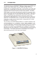
1.1 Introduction The Multi-Tech Systems MultiFRAD™ 100-Series, Model number FR111, is a one-port Frame Relay Access Device (FRAD) with 56K DSU that encapsulates non-packetized data from a serial device into frame relay frames and is responsible for framing that data with header and trailer information prior to transmission to a frame relay network. The MultiFRAD allows a non-frame relay device to connect to a common carrier frame relay network service or private frame relay network.
1.2 About This Manual This manual describes the MultiFRAD, and tells you how to install and configure the unit. The information contained in each chapter is as follows: Chapter 1 - Introduction and Description Chapter 1 introduces the MultiFRAD 100-Series. A typical application is presented with a discussion on ordering a frame relay line and how to configure a MultiFRAD. A list of relevant specifications are provided at the end of the chapter.
Chapter 6 - ASCII Terminal Menu System Chapter 6 provides a description of the ASCII terminal menu system. The ASCII terminal menu system is used when a dumb terminal is connected to the data port. These menus allow you to configure the data port and trunk, view statistics, reset the unit, and enable diagnostics.
1.3 A Typical Application A typical application for a MultiFRAD 100-Series is connecting a single non-frame relay device to a frame relay network. The MultiFRAD 100Series is usually used at a remote site where a single DLCI and a single device needs to be connected to a frame relay network. A MultiFRAD 100-Series can connect any existing synchronous or asynchronous non-frame relay device to a frame relay network.
your capability to present data to the local telephone switch. Your capability to present data is determined by the internal DSU (Data Service Unit) that can transfer digital data at a maximum rate of 56,000 bits-per-second to the network. A general rule of thumb in this scenario is to assign a CIR of 32K bps and an excess burst rate (Be) of 24K bps. The sum of the CIR and Be can not exceed your capability to present data to the network.
length, parity, stop bits, and flow control. The Async Data Port Configuration dialog box displays the default parameters that may apply to a majority async devices. When the data device is defined, then the trunk configuration needs to be defined. The trunk configuration is displayed in the Trunk Configuration dialog box. Most of the trunk information is supplied by your network service provider.
tion. The trunk configuration would be complete by clicking on the Save button and returning to the Main menu. In the Main menu, click on the download button to transfer the configuration to the MultiFRAD. Within a few seconds the new configuration is downloaded to the MultiFRAD and it is ready for operation.
1.4 FCC Regulations for Telephone Line Interconnection 1. This equipment complies with Part 68 of the FCC rules. On the outside surface of this equipment is a label that contains, among other information, the FCC registration number and ringer equivalence number (REN). If requested, this information must be provided to the telephone company. 2. As indicated below the suitable jack (USOC connecting arrangement) for this equipment is shown.
commission or corporation commission for information.) 9. If so required, this equipment is hearing aid compatible. Manufacturer: Multi-Tech Systems, Inc. Model Number: MultiFRAD 100-Series FCC Registration Number: AU7USA-24704-XD-N Ringer Equivalence: N/A Modular Jack (USOC) RJ48 Service Center in U.S.A. Multi-Tech Systems Inc. 2205 Woodale Drive Mounds View, MN 55112 USA (612) 785-3500 or (800) 328-9717 U.S.
1.5 Canadian Limitations Notice Notice: The ringer equivalence number (REN) assigned to each terminal device provides an indication of the maximum number of terminals allowed to be connected to a telephone interface. The termination of a interface may consist of any combination of devices subject only to the requirement that the sum of the ringer equivalence numbers of all the devices does not exceed 5. Notice: The Industry Canada label identifies certificated equipment.
1.6 Specifications Data Port • Single data port with synchronous or asynchronous data format • Async data rate up to 57.6K bps or sync data rate up to 56K bps • RS232C and ITU-T V.35 interface using an adapter cable • Internal shunt plugs to configure RS232C or ITU-T V.
2 Front and Back Panel Descriptions 21
2.1 Introduction This chapter describes the front panel LEDs and back panel connectors. The front panel has one row of LEDs for both the data channel and trunk status. Two back panel connectors provide the data and trunk connections. A circular power connector is provided to connect the external power supply. 2.2 Front Panel The front panel contains two sets of LEDs that provide the status of the data and trunk connections. The data LEDs display the activity of the data port, if V.
received - on for a space and off for a mark. DSU Data Service Unit (DSU) LED lights when the unit is in the DSU-only mode. NS The No Signal (NS) LED lights when no signal is received from the network or when the signal is too weak for normal operation. OOS The Out Of Service (OOS) LED lights when an outage condition occurs. This happens when there is a failure in the digital service that is detected by the network and the telco sends a repetitive OOS sequence.
2.3 Back Panel The cable connections for the MultiFRAD are made at the back panel. Two cable connections are provided and one power supply connection. The Data connector allows the MultiFRAD to be connected to a nonframe relay device and the Trunk connector connects to a common carrier frame relay network service or private frame relay networks. The cable connections are shown in Figure 2-2 and defined in the following sections. Power Data Trunk Figure 2-2.
2.4 Switch Settings The 8-position DIP switch located on the right side of the MultiFRAD only uses the first four positions. The DIP switches are shown in Figure 2-3 and their settings are described in Table 2-1. DIP-Switches Figure 2-3. Switch Settings Table 2-1.
2.5 Shunts V.35 signal levels are generally more reliable for high speed data and/ or longer cable distances. EIA-232D signal levels are intended for data rates of 19,200 bps or less and cable lengths of 50 feet or less. For higher speeds and/or longer distances, V.35 is generally preferred. There are two shunt positions on the printed circuit board that configure the data port for either RS232 or V.35 interface. Both DIP sockets for the shunts are shown in Figure 2-4. V.
3 Setup
3.1 Introduction This chapter describes the unpacking of the MultiFRAD, cable connections depending on whether EIA-232D or ITU-T V.35 interface signaling is used on the data port, and how to configure the unit dependent on your site situation. Once the MultiFRAD is configured, then the data port can be connected to your data port device. 3.2 Unpacking The shipping box contains the MultiFRAD, power adapter, and your owner's manual. Inspect the contents for signs of any shipping damage.
3.4 Setup Use the following steps to setup your MultiFRAD. If V.35 electrical interface signaling is required on the data port, but a pc with EIA-232D signaling is being used to configure the MultiFRAD, the unit has to be configured before you change to V.35 signaling. Perform the following procedure to connect your cables, configure the unit, and then change to V.35 signaling on the data port. 1. Ensure that the DIP-Switch settings on the side of the unit are set for a command mode of operation.
4. Connect an RJ48 phone cable to the Trunk connector on the back of the MultiFRAD. Connect the other end of the phone cable to the local access line jack. Power Data Trunk Figure 3-4. Trunk Connection 5. The MultiFRAD can be configured in two ways: If a pc running a Windows software is being used to configure the unit, refer to the Software Loading procedure in Chapter 4.
3.5 V.35 Shunt Either EIA-232D or ITU-T V.35 electrical signal interface can be selected on the data port. Units are shipped with EIA-232D signal levels selected. Use the following procedure to select V.35. CAUTION This procedure requires opening the unit. Like most products of this type, this product contains components that are sensitive to static and static discharge. Please use your best efforts to avoid static discharge when contacting the components inside this unit.
4 Software Loading and Configuration 35
4.1 Introduction This chapter covers the loading of the software utility and then the configuration of the unit from either a Windows based pc or a dumb terminal. When a Windows based pc is used, the software utility is loaded using the procedures in section 4.2 and then the unit is configured using the procedures in section 4.3. If a dumb terminal is used, the MulitFRAD 100 can be configured using the ASCII terminal menu system present in memory of the unit. 4.
Click on Install to continue installation, at any time you may click on Abort if you wish to cancel the install immediately. 9 The Expanding/Copying Files From: dialog box is displayed. You can view the progress of the installation from this dialog box. You can click on Abort at any time to cancel the install. 11 The MultiFRAD 100 Installation dialog box asks "Please select a communication port for the setup utility to use" dialog box is displayed.
Select the COM port (COM1,COM2,COM3, or COM4) for the setup utility. The default port is COM1. Click on OK when you are satisfied with your selection. 12 When the setup installation is successful, a system message is displayed stating "MultiFRAD 100 Installation Successful. Click on OK to continue. 13 Your are returned to the Program Manager where the MultiFRAD program group and icons are created. This completes the software loading. Now, proceed to configuring your MultiFRAD.
4.3 Configuring Your MultiFRAD using Windows Configuration of your MultiFRAD using Windows starts after the software is loaded and program group is displayed in the Program Manager. 1 Double click on the MultiFRAD 100 Configuration icon. 2 When the MultiFRAD 100 dialog box is displayed, click on the Data Port button to display the Data Port Configuration dialog box. 3 The Data Port Configuration dialog box is displayed with the Mode set to Asynchronous.
If your data device is a synchronous device, click on the Synchronous option button and the parameters for the synchronous mode are displayed. Refer to the User documentation to set the sync parameters that meet the conditions of your installation. 4 When you are satisfied with your selections, click on the Save button to save your new parameters. Then click on the OK button to return to the main menu. 5 From the Main menu, click on the Trunk button to display the Trunk Configuration dialog box.
6 Click on the DLCI numeric dialog box. Enter the DLCI number that was provided by your service provider at subscription time. To change the DLCI, click on the DLCI numeric dialog box and back space through the default number and then enter your DLCI. 7 Click on the Management type option button supported by your Frame Relay network. The Management type is supplied by your service provider at subscription time. For most applications, the default Management Parameters should be adequate.
another MultiFRAD 100. Raw Mode encapsulation can be used for any type of FRAD at the other end. 12 Click on the OK button to return to the Main menu. 13 Click on the Download button to write the new configuration to the MultiFRAD. 14 The Configuration dialog box is displayed. The Configuration downloaded successfully. Reset the unit for configuration to take effect and put dip switch number 1 in the up position. Click on OK to proceed.
4.4 Configuring your MultiFRAD using a Dumb Terminal To configure your MultiFRAD, power up a terminal or pc running communications software and hit the ENTER key. The Main menu appears on your screen, configure the data port for sync or async mode of operation and the trunk for the frame relay parameters. The MultiFRAD configuration is contained in the following procedure. 1 Apply power to your terminal or pc. After the terminal or pc boots up, run the communications software.
4 If the data port is being setup for Async mode of operation and a port speed of 57.6K, initially the data port does not have to be changed, proceed to step 6 to configuring the Trunk.
6 From the Configuration menu, enter 2 and press ENTER. The Trunk Configuration menu is displayed.
Enter the number that corresponds to the DLCI for your trunk. A two-digit number can be entered and the zeros will proceed the digits. The DLCI is supplied by your network service provider at the time the trunk was provisioned. When you have entered your DLCI, the Trunk Configuration menu is displayed. 8 From the Trunk Configuration menu, enter option 5 Committed Info Rate (CIR) and the CIR menu is displayed. Enter the CIR (Committed Information Rate), in units of 1000 (1K).
The Be is supplied by your network service provider at the time the trunk was provisioned. When you have entered your Be, the Trunk Configuration menu is displayed. 10 From the Trunk Configuration menu, enter option 7 Management Type and the Management Type menu is displayed. Management Type 1 2 3 P - Annex D (ANSI T1.617) LMI Annex A (ITU-T Q.933) Previous Menu Selection : _ Enter the number that corresponds to the Management Type for your trunk.
Enter the Full Status Counter. Valid values are between 1 and 255. x P - Enter Number, or - Previous Menu Selection : _ Enter the number between 1 and 255 that is going to be the number of polling cycles (minus one) before a full status is requested from the network. 13 From the Trunk Configuration menu, enter option 10 Error Threshold and the Error Threshold menu is displayed. Enter the Error Threshold. Valid values are between 1 and 10.
15 Enter the letter S and press ENTER to store all configurations. Then enter the letter M and press ENTER to return to the Main Menu. Enter 5 to Exit Command Mode. 16 Place the Command Mode switch (Switch 1) on the side of the MultiFRAD in the UP position and return to step 6 in the Setup procedure in Chapter 3.
5 Software Utility Descriptions
5.1 Introduction This chapter describes the MultiFRAD software which is designed for the Microsoft® Windows® environment. The MultiFRAD 100 Program Group has three icons that allow you to launch the software, download a firmware update, and configure the console pc port in order to communicate with the MultiFRAD.
5.2.1 Configuration Data Port This button allows you configure the data port for either synchronous or asynchronous mode of operation. Trunk This button lets you define the frame relay parameters. 5.2.2 Others Statistics This button allows you to view statistics of the trunk port. Diagnostics This button allows you to run two loopback tests, a memory test, and watch dog test. 5.2.3 Download You can update the MultiFRAD setup on the target. This will bring the MultiFRAD down for updating the setup.
5.2.5 Help A thorough On-line Help system is provided with abbreviated information on the dialog boxes and the buttons within a dialog box. 5.2.6 MultiFRAD Version The current version number of the MultiFRAD firmware is displayed in this field.
5.3 Data Port Configuration This dialog box allows you to configure the data port. You will be able to set the parameters required for the successful operation of the port. Mode Asynchronous/Synchronous This allows you to set synchronous or asynchronous parameters required for transferring data between the MultiFRAD and the data port device. The data port can operate either in Asynchronous (UART) mode or Synchronous (HDLC) mode. Choose the Mode option that meets your site requirements.
Note: The MultiFRAD always provides the clocking signal to the sync device. The MultiFRAD 100's data port can not be set to external clocking, it is always internal clocking. Between Frames The Between Frames parameter must be set to match the idle condition of the synchronous device connected to the data port. The Between Frames determine what happens when the synchronous data line is idle (i.e., no data frames are being transmitted). The default condition is to continuously send SDLC flags (Flags).
CRC Preset The CRC Preset parameter allows the user to specify whether the polynomial used to calculate the CRC for each frame is preset to all 1s or all 0s. This option must match the synchronous device’s CRC-preset setting. The default is All 1s. Async Mode Parameters Following Parameters are modifiable when the device connected to the data connector on the back of the MultiFRAD 100-Series is an asynchronous device.
Parity The Parity parameter sets parity for odd, even or none. Under normal conditions, parity is set to none. The default is none. Stop Bits The Stop Bits parameter sets the number of stop bits. The number of stop bits can be 1, 1.5, or 2. The default is 1 bit. Flow Control The Flow Control parameter allows for two types of flow control: the software-based XON/XOFF and the hardware-based Clear to Send (CTS). The default is CTS.
Pass Xon The Pass Xon parameter enables the XON/XOFF flow control signals to be passed on to the data device. This option has to be used in conjunction with the software-based XON/XOFF flow control option. The default condition is for this option to be turned off, and normally it should remain off. Echo The Echo parameter enables data entered on the data device keyboard to be returned to the device's monitor.
ENQ/ACK The Enq/Ack parameter is a special flow control protocol used in Hewlett Packard computer systems. This option is sometimes referred to as Enquire/Acknowledge flow control because it’s based on the computer sending an enquiry (ENQ) and then expecting an acknowledgment (ACK).
5.4 Trunk Configuration This dialog box allows you to configure the trunk. You will be able to set the parameters required for the successful operation of the trunk. Frame Relay is a multiplexing protocol designed to operate over transmission facilities that are virtually error free. In Frame Relay, frames are routed through the network on the basis of an attached label called a Data Link Connection Identifier (DLCI).
LMI describes a protocol and associated procedures operating on the local interface between the user and the network. It notifies the user of the addition, deletion, and presence of the PVC in the network. It also notifies the user of the end-to-end availability or unavailability of a PVC. Basic LMI protocol is based on a synchronous polling scheme where the user polls the network to obtain status information on the PVCs configured on the interface.
Full Status Counter The Full Status Counter determines how may Polling Intervals take place before a full status is requested from the network. A full status enquiry message is sent from the MultiFRAD to the network requesting a status report of the PVC on the physical link. The Full Status Counter can range from 1 to 255, with a default of 6. Error Threshold The Error Threshold is used to indicate the threshold number of errors occurring during a full cycle of the Monitored Event.
Back to Back The Back to Back is used to test the port by connecting two MultiFRADs together without a frame relay network in between them. Back-to-back mode still requires the use of DSU/CSUs, but they should not be connected over the frame relay network. The options are On and Off with a default of Off. Back-to-back mode is useful when two MultiFRADs are at the same location and they are connected via DSUs for testing.
5.5 Statistics This dialog box allows you to view status of the trunk. Its possible to view signal status and other characteristics like data frames transmitted or received, status of enquiries transmitted and messages received and the status of the messages received. If you want to clear the statistics so that you can have fresh statistics, then you should click on the clear button. 5.
Loop Tests The loop tests provide a short and long loop test. The short loop test is the data port loopback test which loops back the data from the data port to the sending device (DTE). The long loop test is the trunk loopback test which again receives data from the DTE device and loops it back from the internal DSU. The data port loopback test has two modes which depend on the device connected to the data port.
6 ASCII Terminal Menu System
6.1 Introduction The menu system for the MultiFRAD provides a set of user-friendly configuration menus that are accessible from a main menu. The Main Menu contains five options that allow you to configure your MultiFRAD; display statistics; reset the unit or data port; run diagnostic tests, and exit the command mode. To select one of the options from the Main Menu, enter the number corresponding to the option and press ENTER.
a message will appear on your screen saying to wait for 3 seconds. Then press ENTER to return to the Main Menu. To store the current configuration, enter S and press ENTER. To return to the Main Menu, enter M and press ENTER. 6.2.1 Async Data Port Configuration The Async Data Port Configuration menu allows you to configure the data channel for either asynchronous or synchronous operation, depending on the type of device connected to the data port.
The Word Length option sets the number of bits in a word. The word length range is 5 to 8 bits. The default is 8 bits. The Stop Bits option sets the number of stop bits. The number of stop bits can be 1, 1.5, or 2. The default is 1 bit. The Parity option sets parity for odd, even or none. Under normal conditions, parity is set to none. The default is none. The Flow Control option allows for two types of flow control: the software-based XON/XOFF and the hardware-based Clear to Send (CTS).
The EIA Pass Through option allows the data device to receive EIA control signals through the MultiFRAD. This option only applies during the async mode of operation. Since, in normal interactive operation, the existence of a MultiFRAD should be transparent to the user, the EIA pass through option allows a terminal to operate as if it were connected directly to a communications line and not through a MultiFRAD.
6.2.2 Sync Data Port Configuration The Sync Data Port Configuration menu allows you to configure the data port for either asynchronous or synchronous operation, depending on the type of device connected to the port.
ing, data is represented normally. With NRZI encoding, a logical one is represented by no transition and a zero is represented by a transition at the beginning of the bit. Most synchronous devices can be configured for either NRZ or NRZI. If a synchronous device is not configurable, it most likely is set to NRZ. Refer to the device’s user documentation for the encoding method.
6.2.3 Trunk Configuration The Trunk Configuration menu allows you to configure the trunk.
access circuit. Set the DLCI to indicate the PVC to terminate the trunk. The range of DLCIs is from 16 to 1007 with a default of 16. The Committed Info Rate (CIR) option determines the data transfer rate at which the network is committed to handle under normal conditions. This rate is the average over a minimum increment of time. The CIR may be less than or equal to the Access Rate.
should be less than or equal to the Monitored Event Counter. The Monitored Event Counter option determines the number of Polling Intervals that have to take place before the User Network Interface is operational. It is also used with the error threshold count to determine if the trunk should be brought down. The range of this counter is from 1 to 10 events with a default of 4 events. The Encapsulation Mode option depends on the type of device that is connected at the other end of the trunk.
6.3 Statistics The Statistics menu allows you to view or clear statistics, or return to the previous menu or to the Main Menu. Statistics 1 - View Statistics 2 - Clear Statistics M - Main Menu P - Previous Menu Selection : _ To view or clear statistics, enter the corresponding option number and press ENTER. To return to the previous menu, enter P and press ENTER. To return to the Main Menu, enter M and press ENTER. Two Trunk Statistics Menus are provided depending on how the data channel is configured.
you might encounter could be 10,000 frames transmitted (or received) with 500 or 1000 retransmits (or receive errors). Link alarms simply tell you that there is some sort of problem on the trunk in async mode. You will find that the link alarms number will correspond to the retransmit and received frames numbers. Specifically, a link alarm means that it has been 10 seconds since the MultiFRAD has received an acknowledgment. Normally, three acknowledgments are received during a 10second period.
6.4 Reset Options The Reset Options menu allows you to reset the unit, the data channel, or return to the previous menu or to the Main Menu. Reset Options 1 2 M P - Reset Unit Reset Data Channel Main Menu Previous Menu Selection : _ To reset the unit, enter 1 and press ENTER. To reset the data channel, enter 2 and press ENTER. To return to the previous menu, enter P and press ENTER. To return to the Main Menu, enter M and press ENTER. 6.
loopback mode (DIP-Switch 3 DOWN). This tests the complete path through the MultiFRAD up to the line circuitry and back to the data port. When it is used in a remote trunk loopback test mode, the remote DSU (or the telephone company's central office, CO) would be put into loopback mode. This tests the integrity of the local data device, MultiFRAD, and the frame relay network. The Remote Trunk Loopback test is the most sophisticated of the two tests.
try going back to the Local Trunk Loopback, and then even the data port loopback which is the most basic test. If there is still no clear cause of the problem, follow the steps in section 7.3, contacting Tech support. 6.5.2 Memory Test The memory test verifies that each memory chip on the circuit board is working. The memory test destroys all stored parameters. 6.5.3 Watch Dog Test The watch dog is a special circuit designed to reset the unit in case of a catastrophic error in the firmware.
7 Service, Warranty and Tech Support
7.1 Introduction This chapter begins with your MultiFRAD 100-Series 2-year warranty. Read carefully the next section, “Tech Support,” if you have questions about or problems with your MultiFRAD. It includes the technical support telephone numbers, space for recording your product information, and an explanation of how to send in your MultiFRAD should you require service. The final three sections explain how to use our bulletin board service (BBS), and get support through CompuServe and the Internet. 7.
7.3.1 Recording MultiFRAD Information Please fill in the following information on your Multi-Tech MultiFRAD. This will help Tech Support in answering your questions. (The same information is requested on the Warranty Registration Card.) Model Number: ______________________________________ Serial Number: ______________________________________ Firmware Version: ____________________________________ The model and serial numbers are on the bottom of your MultiFRAD.
7.3.2 Service If your tech support specialist decides that service is required, your MultiFRAD may be sent (freight prepaid) to our factory. Return shipping charges will be paid by Multi-Tech Systems. Include the following with your MultiFRAD: • A description of the problem. • Return billing and shipping addresses. • Contact name and phone number. • Check or purchase order number for payment if the MultiFRAD is out of warranty.
7.4.1 Logging on to the Multi-Tech BBS To log on to the Multi-Tech BBS, perform the following steps. 1. Set your communications program to 8-N-1. 2. Dial our BBS at (800) 392-2432 (USA and Canada) or (612) 7853702 (international and local). 3. At the prompts, type your first name, last name, and password; then press ENTER. If you are a first time caller, the BBS will ask if your name is spelled correctly. If you answer yes, a questionnaire will appear.
If you don’t know the file name 1. From the Main Menu, type F to access the Files Menu. For a list of file areas, type L, press ENTER, then type L and press ENTER again. (If you do not type the second L, you will list all of the files on the BBS.) 2. Mark each file area you would like to examine by typing its list number and pressing ENTER. 3. Enter L to list all the files in the selected file areas. Enter C to go forward in the file list and P to go back. 4.
7.6 About the Internet Multi-Tech is a commercial user on the Internet, and we retrieve messages from our customers on a periodic basis. Multi-Tech’s presence includes a Web site at: http://www.multitech.com and an ftp site at: ftp://ftp.multitech.com Multi-Tech's presence includes a Web site at: 7.7 About the Multi-Tech Fax-Back Service Multi-Tech’s fax-back system provides 24-hour access to sales, marketing, and technical literature.
7.8 Upgrading the Flash PROM Your MultiFRAD has a Flash PROM which contains firmware code for the hardware. At various times, Multi-Tech may add enhancements and/ or fixes to the firmware. The Flash technology used in your MultiFRAD allows these upgrades to be loaded directly into the PROM chip through the serial port. 7.8.1 Using FlashPro to Upgrade MultiFRAD Firmware 1. Download FLASHPRO.ZIP and a new .HEX file from the Multi-Tech BBS. 2. Unzip the FLASHPRO.ZIP file.
Appendices
Appendix A Cabling Diagrams Data Cables 13 25 12 11 24 10 23 22 9 8 21 20 7 6 19 5 18 17 4 3 16 2 15 1 14 Data connector RS232C/V.24 * Cable PIN NO. To Data Device Connector PIN NO.
Trunk Cable Receive { Transmit { RT RR RT RR 1 2 3 4 5 6 7 8 RJ-48 Cable Pin Identification 98 Pin Description Destination 1 2 3 4 5 6 7 8 Transmit Pair Transmit Pair N/C N/C N/C N/C Receive Pair Receive Pair To Line To Line From Line From Line
Back-To-Back Cable 8 7 6 5 4 RJ48S 3 2 1 1 2 3 4 RJ48S 5 6 7 8 1 8 99