CommPlete 4000 Communications Server User Guide
CommPlete 4000 Communications Server User Guide S000348A, Revision A This publication may not be reproduced, in whole or in part, without prior expressed written permission from Multi-Tech Systems, Inc. All rights reserved. Copyright © 2004, by Multi-Tech Systems, Inc. Multi-Tech Systems, Inc. makes no representations or warranties with respect to the contents hereof and specifically disclaims any implied warranties of merchantability or fitness for any particular purpose.
Contents System Overview ...................................................................................... 5 Product Overview ................................................................................................................................. 5 RASExpress .................................................................................................................................. 6 Documentation Set Overview ..............................................................................
Appendices .............................................................................................. 30 Appendix A—Back Panel Connector Pinouts ..................................................................................... 30 Appendix B—Regulatory Information ................................................................................................. 35 FCC Regulations for Telephone Line Interconnection .........................................................................
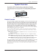
Chapter 1 - System Overview System Overview The CommPlete™ 4000 Communications Server is a single-segment, rack mountable communications server. It is customized for dedicated turnkey operation of LAN-based communications and remote access server functions. The CommPlete 4000 is a general purpose, turnkey communications server that easily interfaces to any existing Novell, Windows NT, or IP network. Figure 1-1.
Chapter 1 - System Overview RASExpress The CommPlete 4000 is equipped with factory installed RASExpress, an advanced remote access software that enables network managers to configure and manage remote servers via web browsers, through Telnet over an IP network, and via a GUI manager over both IP and IPX networks. Through an a special software package bundled with the CommPlete 4000, RASExpress can also be interfaced to standard Radius Authentication functionality (which resides on a separate PC).
Chapter 1 - System Overview Technical Specifications The CommPlete 4000 conforms to the following technical specifications. Chassis • 6-slot PCI/ISA backplane • SBC • One half-height 1.44Mb 3½-inch floppy disk drive • One half-height IDE hard disk drive • One power supply • Power on/off switch on front panel with built in power LED.
Chapter 2 - Installing Your CommPlete 4000 Chapter 2 - Installing Your CommPlete 4000 This chapter explains how to set up and connect cables for the CommPlete 4000. This product is ready to be connected to the end-user's Ethernet concentrator. It is preconfigured to operate as a communications server. The operator must make modem/terminal-adapter connections, link up the VGA monitor and keyboard, boot the system, and enter some basic information.
Chapter 2 - Installing Your CommPlete 4000 If the ISI4608PCI or ISI4608UPCI is used, connections between it and external modems are made via the supplied octopus cable going between the DB-78 connector on the ISI4608PCI board and the DB-25 connectors on the individual modems. (RJ-11 connectors connect the modems to the phone jacks.) If the ISIHP-4S or -4U are used, each ISIHP card accepts as many as four RJ-45 connectors to accommodate ISDN BRI lines.
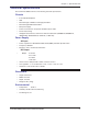
Chapter 2 - Installing Your CommPlete 4000 ISI Board Cabling Each Intelligent Serial Interface card (ISI5634PCI/8, ISI5634UPCI/8, ISI4608PCI, ISI4608UPCI or ISIHP-2S/2U) takes up one physical slot in the CommPlete 4000. Depending on your configuration, you may have as many as four of these cards (see Figure 2-1). Attach the line cords (RJ-12 for analog phone lines; RJ-45 for UPCI or ISDN phone lines) to the line connectors on the ISI card(s) at the back of your CommPlete 4000 as shown in Figure 2-3.
Chapter 2 - Installing Your CommPlete 4000 Serial Card Upgrades As shown in Figure 2-3c, installation of expansion cards is simpler in the outer slots than in the inner expansion slot. Shipped Configuration 120 120 Preferred expansion slots 120 Installing expansion card here requires removal of card cage. } Figure 2-3c.
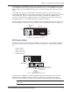
Chapter 2 - Installing Your CommPlete 4000 Powering Up Note: This is pluggable equipment; the socket outlet must be installed near the equipment and must be easily accessible. Make sure that the voltage selector on the power supply is set to the proper voltage prior to connecting this equipment to the main power. If the voltage selector needs to be changed, an ordinary pencil can be used to change the switch to the position which best correlates with the known input voltage.
Chapter 3 - Getting Started with RASExpress Chapter 3 - Getting Started with RASExpress MultiTech Systems has preinstalled RASExpress server software on your CommPlete 4000 to make configuration as simple as possible. For your convenience, a copy of the RASExpress Installation program is on the CD-ROM shipped with the CommPlete 4000. Complete the procedure below to put your CommPlete 4000 into operation as a Remote Access Server.
Chapter 3 - Getting Started with RASExpress Method A. Do All Configuration using Terminal or Auxiliary PC A1. Be sure that the CommPlete 4000 is connected to the LAN. Turn off the power for the CommPlete 4000. A2. Using the provided RS-232C serial cable, connect a terminal (or an auxiliary PC) to the CommPlete 4000’s serial port.
Chapter 3 - Getting Started with RASExpress iii. Select ISI Setup. iv. Delete all ISI cards before saving and rebooting the server. These steps correct the initial subnet error the next time the server loads. If you set the Remote Client IP Address to any of these values (Use DHCP, or Use Address Pool, Use Radius), go to step A15. If you selected Use Address Pool, you must configure the address pool. See the RASExpress User Guide. A15.
Chapter 3 - Getting Started with RASExpress Method B. Start Configuration with Terminal, Finish Configuration on Client PC To enable remote configuration of the RASExpress server, you must first configure the server’s IP settings, including the server’s IP address. To do this, you must connect a terminal (or auxiliary PC) to the server’s serial port.
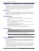
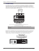
Chapter 3 - Getting Started with RASExpress B10. Using Telnet for access requires that a TCP/IP protocol stack be loaded on the client PC. Telnet access is possible both by dialing in through the RASExpress server and, more commonly , through the LAN or Internet. Client PC running Telnet session, web, or Windows MultiManager CommPlete 4000 RASExpress Server Figure 3-3.
Chapter 4 - Hardware removal/ Replacement Chapter 4 - Hardware removal/Replacement This chapter’s procedures describe removal and replacement of the main hardware components of the CommPlete 4000. Before removing or replacing any component, disconnect the cables from the back of the CommPlete 4000 and remove the CommPlete 4000 from its rack enclosure per instructions.
Chapter 4 - Hardware removal/Replacement 5 To re-attach cables and re-mount the CommPlete 4000, follow steps 1-4 in reverse order and sense. That is, a. (Two people are needed.) Attach the CommPlete 4000 to its rack enclosure using the four mounting screws. b. Reconnect phone cords. c. Reconnect the SBC cables (to video, keyboard, COM1, and network). d. Restore power when ready. Card Cage Removal/Replacement The steps below describe how to remove the card cage.
Chapter 4 - Hardware removal/ Replacement 4 Finish pulling the card cage (including fan enclosure) straight up and out of the chassis. See Figure 4-5. Set it next to the chassis. Note: Before placing the card cage back into the chassis, verify that the power connectors from the power supply to the backplane are fully attached. Figure 4-5b shows the wire colors and correct orientation of the power cables.
Chapter 4 - Hardware removal/Replacement Board Removal and Replacement Removing SBC Board 1 Remove the CommPlete 4000 from rack enclosure (two people are needed). Follow the procedure “Disconnecting Cables and Removal from Enclosure” presented above. Summary: after powering down the unit and disconnecting all power and signal cables, employ two persons to remove its rack-mounting screws and lift the unit out of the rack.
Chapter 4 - Hardware removal/ Replacement 8 If installing other boards, see the procedures below for installation instructions. Then remount the CommPlete 4000 in the enclosure. Removing ISI Boards Note: If removing or replacing the single ISI board on the left side (looking from the front) of the midplane, card cage removal is not necessary. Ignore steps 3 through 5. 1 Remove the CommPlete 4000 from rack enclosure (two people are needed).
Chapter 4 - Hardware removal/Replacement Floppy Disk Drive Removal/Replacement 1 Remove the CommPlete 4000 from rack enclosure (two people are needed). Follow the procedure “Disconnecting Cables and Removal from Enclosure” presented above. Summary: after powering down the unit and disconnecting all power and signal cables, employ two persons to remove its rack-mounting screws and lift the unit out of the rack.
Chapter 4 - Hardware removal/ Replacement Power Supply Removal/Replacement The card cage has to be removed in order to disconnect the power wiring before the power supply can be removed. 1 Remove the CommPlete 4000 from rack enclosure (two people are needed). Follow the procedure “Disconnecting Cables and Removal from Enclosure” presented above.
Chapter 5 - Troubleshooting Chapter 5 - Troubleshooting This chapter provides solutions for solving problems if the CommPlete 4000 fails. Your CommPlete 4000 was tested thoroughly at the factory before it was shipped. If you are unable to make a successful connection, it is possible that the CommPlete 4000 is defective. However, it is more likely that the source of your problem lies elsewhere.
Chapter 5 - Troubleshooting — Check that cables are connected properly and peripherals are powered ON and configured properly. — If problem persists, contact MultiTech's Technical Support department (see Chapter 6). • Keyboard does not respond to key strokes — Connect keyboard cable to the left round connector on SBC. — If cable converter is used to connect a large 5-pin DIN to a small 6-PIN PS/2 DIN, check it (the cable converter) to see if it is defective or the wrong type.
Chapter 6 - Service, Warranty, and Technical Support Chapter 6 - Service, Warranty, and Technical Support This chapter begins with your CommPlete 4000's 2-year warranty. If you have questions or problems with your unit carefully read the next section, Technical Support. It includes the technical support telephone numbers and information on how to send in your CommPlete 4000 should you require service. Limited Warranty Multi-Tech Systems, Inc.
Chapter 6 - Service, Warranty, and Technical Support Addendum for International Products Distributors should contact Amex, Inc., for information about the repairs for your Multi-Tech product. Amex, Inc. 2724 Summer Street NE Minneapolis, MN 55413 U.S.A. Tel: +(612) 331-3251 Fax: +(612) 331-3180 Please direct your questions regarding technical matters, product configuration, verification that the product is defective, etc., to our Technical Support department nearest you. When calling the U.S.
Appendices Contacting Technical Support ...Using email ...By phone U.S. & Canada tsupport@multitech.com 800-972-2439 or 763-785-3500 France support@multitech.fr +(33) 1-64 61 09 81 Germany technical@de.multitech.com +(49) 89028-0 China support@multi-tech.com.cn +(86) 10-68748015 India support@multitechindia.com +(91) 124-340778 U.K. & Europe support@multitech.co.
Appendices Appendices Appendix A—Back Panel Connector Pinouts This appendix provides specifications for the various connectors on the back panel of the MiniArray. VGA 15-Pin Connector This connector provides video analog data and horizontal and vertical synchronization signals for VGA monitors. 1 5 10 6 11 15 Figure A-1.
Appendices 9-Pin DB9 (COM 1) Connector This connector attaches the SBC board to the COM 1 serial port. 5 1 6 9 Figure A-2. 9-Pin DB9 COM 1 Connector Pin Identification Pin 1 2 3 4 5 6 7 8 9 Description DCD RX Data TX Data DTR Ground DSR RTS CTS RI 6-Pin Circular Jack This connector connects the keyboard to the SBC board. 5 6 4 3 2 1 Figure A-3.
Appendices RJ-45 Connector This connector ties the EN-Series Ethernet board to a 10BASET network. 1 8 Figure A-5. RJ-45 Connector (viewed from connector side) Pin Identification Pin 1 2 3 4 5 6 7 8 Description + Transmit Data - Transmit Data + Receive Data No Connect No Connect -Receive Data No Connect No Connect 34-Pin Floppy Disk Drive Connector This connector provides signal and data connection between the floppy drive and the SBC board. 2 34 1 33 Figure A-4.
Appendices Printer Port Connector This 25-pin connector provides parallel printer data and control signals to and from the SBC board. 2 26 1 25 Figure A-5.
Appendices Hard Disk Connector This connector supplies hard disk drive signals which interface with the software I/O drivers to provide the read/write functions. 2 40 1 39 Figure A-7.
Appendices Appendix B—Regulatory Information FCC Regulations for Telephone Line Interconnection 1. 2. 3. 4. 5. 6. 7. 8. 9. This equipment complies with Part 68 of the Federal Communications Commission (FCC) rules. On the outside surface of this equipment is a label that contains, among other information, the FCC registration number and ringer equivalence number (REN). If requested, this information must be provided to the telephone company.
Appendices Canadian Limitations Notice Notice: The ringer equivalence number (REN) assigned to each terminal device provides an indication of the maximum number of terminals allowed to be connected to a telephone interface. The termination of a interface may consist of any combination of devices subject only to the requirement that the sum of the ringer equivalence numbers of all the devices does not exceed 5. Notice: The Industry Canada label identifies certificated equipment.
Appendices Compliance with BABT Requirements Approved for connection to telecommunications system specified in the instructions for use subject to the conditions set out in them. Warning: Interconnection directly, or by way of other apparatus, of ports marked "SAFETY WARNING see instructions for use" with ports marked or not so marked may produce hazardous conditions on the network. Advice should be obtained from a competent engineer before such a connection is made.
Appendices Carrier Card Expansion Card Communication Module X Power Supply Unit or other source of excessive voltage X Y Y Example Diagram Showing Creepage and Clearance Distances Fig. B-1.
Appendices Compliance with BS6305 Clause 6.2, BS6320 Clause 7.2, and BABT/ SITS/82/005S/D a. The modem is suitable for connection to the Public Switched Telephone Network (PSTN) provided by British Telecommunications plc or Kingston Communications (Hull) plc. Circuit supply by British Communications, Mercury Communication, or Hull City Council. Only direct exchange lines may be used, not shared service. b. The modem is suitable for household, office, and similar general indoor use.
c:\jeff\modems\int'l