ISI5634PCI/4/8 User Guide
User Guide Model ISI5634PCI/4/8 P/N S000246B, Revision B This publication may not be reproduced, in whole or in part, without prior expressed written permission from MultiTech Systems, Inc. All rights reserved. Copyright © 2003 by Multi-Tech Systems, Inc. Multi-Tech Systems, Inc. makes no representation or warranties with respect to the contents hereof and specifically disclaims any implied warranties of merchantability or fitness for any particular purpose. Furthermore, Multi-Tech Systems, Inc.
Contents Chapter 1—Introduction and Description ........................................................................ 5 Introduction ................................................................................................................................................. 6 ISI5634PCI Modems ................................................................................................................................... 6 IntelligentSerialInterface .................................................
LINUX-RPM: Pre-Installation Issues ................................................................................................... 55 LINUX-RPM: Copying the driver from the media ................................................................................ 55 LINUX-RPM: Copying the driver from CD-ROM ................................................................................. 55 LINUX-RPM: Copying the driver from a floppy ..........................................................................
Chapter 1—Introduction and Description
ISI5634PCI/4/8 User Guide Introduction Welcome to the world of data communications. You have acquired one of the finest intelligent data and fax modems available today from one of America’s oldest and most respected modem manufacturers— Multi-Tech Systems, Inc. The new IntelligentSerialInterface card, model ISI5634PCI is a multiport serial port expansion card with four V.92 data/Super G3 fax modems. The card’s capability can be doubled by adding an auxiliary module, which also contains four modems.
Chapter 1—Introduction and Description The processor, along with 256K bytes of RAM, works to allocate resources dynamically to the most active port. The ISI then generates one interrupt for an entire block of information and transfers the block to the system’s microprocessor. The ISI5634PCI has eight Mini RJ-11 jacks. It is a 3/4 size add-on card that supports a high-speed interface up to 230 Kbps.
ISI5634PCI/4/8 User Guide Technical Specifications Computer Requirements • • Pentium®- based PC or compatible with PCI Bus Architecture One of these operating systems: Microsoft Windows 2000, NT v. 3.51 or v. 4.0; Windows 95, Windows 98 and Windows Me; Novell Netware versions 3.x and 4.x., SCO Open Server 5; Linux. • A CD-ROM drive. • 100K bytes of hard disk space Physical/Electrical/Environmental • Dimensions: 6.875" x 4.2" 17.46 cm x 10.
Chapter 2—Hardware Installation
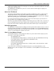
ISI5634PCI/4/8 User Guide Introduction Included in this chapter are two sets of instructions for installing the Multi-Tech ISI5634PCI card in your PCI bus personal computer. The first set of instructions is for installing the ISI5634PCI card. The second set contain instructions for installing the ISI5634PCI card and the auxiliary module. Safety Warnings Telecom 1. Never install telephone wiring during a lightning storm. 2.
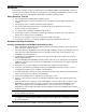
Chapter 2—Hardware Installation Installing the ISI5634PCI card WITH the auxiliary module: 1. The auxiliary module attaches to the ISI5634PCI card. If you already have this card installed, you must remove it from the PC to install the auxiliary module. 2. Before handling the ISI5634PCI card or the auxiliary module, discharge any static in your body by touching a piece of grounded metal such as the computer chassis. 3.
ISI5634PCI/4/8 User Guide 12
Chapter 3 -- Driver Installation
ISI5634PCI/4/8 User Guide Introduction The ISI5634PCI card ships with drivers for each of the following operating systems: Windows® 2000, Windows NT, Windows 95, Windows 98, Windows Me, Novell Netware versions 3.x and 4.x, SCO Open Server 5, and Linux. This chapter describes the installation of these drivers. In most cases, you will receive the ISI drivers on a CD-ROM. In certain situations, however, drivers may be downloaded from the MultiTech web site, often onto diskette, and then installed.
Chapter 3—Driver Installation 5. The Install Hardware Device Drivers screen appears. Select "Search for a suitable driver ..." and click Next. 6. The Locate Driver Files screen appears (Windows 2000 is seeking the driver for the ISI5634PCI card). Select “CD-ROM drives” and click Next.
ISI5634PCI/4/8 User Guide 7. The Driver File Search Results screen appears. Click Next. 8. 16 A progress screen will appear briefly while files are being copied.
Chapter 3—Driver Installation 9. A completion screen will appear. Click Finish. 10. Immediately after the ISI driver installation has been completed, another Found New Hardware screen will appear briefly indicating that the “MultiTech ISI Port” has been detected.
ISI5634PCI/4/8 User Guide A second sequence of ‘installation wizard’ screens appears. This sequence of screens deals with the setting up of ISI ports. The first screen in this sequence is the Found New Hardware Wizard -Welcome screen. The Found New Hardware -- MultiTech ISI Port screen will appear once for each modem on the ISI5634PCI card: • 8 times for the ISI5634PCI-8; or, • 4 times for the ISI5634PCI-4. 11. The Install Hardware Device Drivers screen appears. Select “Search for a suitable driver ...
Chapter 3—Driver Installation 12. The Locate Driver Files screen appears (Windows 2000 is seeking the ISI Port device driver). Select “CD-ROM drives” and click Next. 13. The Driver Files Search Results screen will indicate that the “isiport.inf” file has been found on the CD-ROM. Click Next.
ISI5634PCI/4/8 User Guide 14. A completion screen will appear. It will indicate that the first “MultiTech ISI Port” has been set up successfully. Click Finish. Notice that the auto-detection facility of Windows 2000 will repeat the “ISI Port” installation sequence 3 more times for ISI5634PCI-4, or 7 more times for ISI5634PCI-8. That is, the Found New Hardware -- MultiTech ISI Port screen will appear many times after the ISI driver has been located.
Chapter 3—Driver Installation Windows 2000: Installing Modems to COM Ports Pre-Requisite: Installation of Windows 2000 driver software must be completed before you can install the modems of the ISI5634PCI card. 1. Go to Start | Settings | Control Panel | Phone and Modem Options. 2. The Location Information screen appears. Enter the appropriate area code and access number. Click OK. 3. At the Phone and Modem Options screen, click on the Modems tab and click Add.
ISI5634PCI/4/8 User Guide 4. At the Install New Modem screen, click on "Don't detect my modem ... " and click Next. 5. If the ISI Family CD-ROM (or other media, in cases of using drivers downloaded from the MultiTech web site) is not already in the appropriate disk drive in the PC, insert it now. 6. The Add/Remove Hardware Wizard screen will appear. Click “Have Disk ... .
Chapter 3—Driver Installation 7. The Install from Disk screen will appear. Type or browse for the file path of the modem software (for example, E:\servcard\drivers\win2000). Click OK. 8. The Install New Modem screen will appear. Highlight “ISI5634PCI -8 PCI 56K Modem.” Click Next.
ISI5634PCI/4/8 User Guide 9. The ‘Install New Modem - port list’ screen will appear. Highlight the COM ports on which you want modems to be installed. You must allocate 4 ports for the ISI5634PCI-4, or 8 ports for the ISI5634PCI-8. Click Next. 10. A progress screen will appear as modem installation begins. 11. Screens denoting the installation of modems to specific COM ports will appear for each modem installed.
Chapter 3—Driver Installation 12. A completion screen will appear. Click Finish. 13. The Phone and Modems Options screen (Modems tab) will re-appear and display the modems that have just been assigned to COM ports. Installation of modems to COM ports in Windows 2000 is now complete.
ISI5634PCI/4/8 User Guide Windows 2000: Removing ISI5634PCI Driver 1. Go to Start | Settings | Control Panel. 2. Click on Add/Remove Hardware. Click Next. 3. Click on “Uninstall/Unplug a device” and click Next. 4. In the subsequent screen, click on “Uninstall a device” and click Next. 5. At the Add/Remove Hardware Wizard screen, highlight the ISI driver file for the specific server card that you intend to remove. Click Next. 6.
Chapter 3—Driver Installation Windows NT: Driver Installation The following procedure describes how to install the ISI5634PCI in a system operating Microsoft Windows NT 3.51 or 4.0 for use with Remote Access Service (RAS) server and other communications/ fax server type applications. These procedures apply to both 3.51 and 4.0. 1. Ensure that your ISI5634PCI card has been installed according to the Hardware Installation Procedures in Chapter 2. 2. Turn on the PC and start Windows NT. 3.
ISI5634PCI/4/8 User Guide 5. The Select Network Adapter dialog box appears. Click Have Disk. 6. The Insert Disk dialog box appears. Type in or browse for the path (file directory location) of the Windows NT driver (for example, E:\servcard\drivers\winnt\setup.exe). Click OK. 7. The Select OEM Option dialog box appears. Click OK. The driver files will be copied from the installation CD-ROM. 8. 28 A transient dialog box will appear indicating the progress of the setup program.
Chapter 3—Driver Installation 9. Then the ISI Card Settings dialog box appears. In the Port Count field, enter the correct port count, as follows: • allocate 4 ports for the ISI5634PCI-4 • allocate 8 ports for the ISI5634PCI-8 Select the first port number (Starting Port field) for ISI5634PCI modems. Typically, in a newly outfitted server, this will be COM3. In the Bus Type field, select “PCI.” When the correct settings have been made, click Done. 10.
ISI5634PCI/4/8 User Guide 11. The Multi-Tech 8-port PCI Card appears in the Network Adapters dialog box. Click Close. 12. After bindings are reviewed and stored, the Network Settings Change dialog box appears. Click Yes to reboot your system. The ISI5634PCI now is installed in Windows NT and you are ready to install modems.
Chapter 3—Driver Installation Windows NT: Installing Modems to COM Ports 1. Click Start | Settings | Control Panel, and double-click the Modems icon. 2. The Modem Properties dialog box appears. Click Add. 3. The Install New Modem dialog box appears. Check the box marked Don’t detect my modem; I will select it from a list and click Next. 4. The Install New Modem - Models dialog box appears. Highlight “ISI5634PCI-8 PCI 56K Modem” and click Next.
ISI5634PCI/4/8 User Guide 5. Select ports for modem use. • For the ISI5634PCI-4, you should have reserved four ports during driver installation. Highlight four ports in the list. • For the ISI5634PCI-8, you should have reserved 8 ports during driver installation. Highlight eight ports in the list. Click Next. The modems will be installed to the selected COM ports. 6. 32 After the modems install to the ports, click Finish to return to the General tab.
Chapter 3—Driver Installation 7. To view COM port assignments (and make changes if necessary), use the Modem Properties dialog box. 8. When finished, close the Modem Properties dialog box. The message below appears asking if you want to configure Dial-Up Networking. Click Yes.
ISI5634PCI/4/8 User Guide 9. The Remote Access Setup dialog box appears. Click Add. 10. Each COM port appears in a separate Add RAS Device dialog box. To add the highlighted device, click OK. 11. The Remote Access Setup dialog box displays again. Repeat steps 9 and 10 until all modems are added. 12. When all modems have been added, click Continue.
Chapter 3—Driver Installation 13. After bindings have been reviewed and stored, you will be prompted to re-start your computer. Click Yes. You have completed installation of modems to COM ports and configuration of RAS in Windows NT. Note: By default, Microsoft sets the serial baud rate at 57,600 bps. For improved performance, you can raise the serial baud rate. To do so, go to Start | Settings | Control Panel. Click on the Modems icon.
ISI5634PCI/4/8 User Guide Windows 95/98/Me: Driver Installation Procedure 1. Ensure that your ISI5634PCI card has been installed according to the Hardware Installation Procedures in Chapter 2. 2. Turn on the PC and start Windows 95/98/Me. 3. Windows will autodetect the ISI5634PCI card. When the Add New Hardware Wizard screen appears, click Cancel. 4. Insert the ISI Family CD-ROM into the CD-ROM drive.
Chapter 3—Driver Installation 8. Under Select Type of Card, do not check the Install ISA Card box. Click Next. 9. A completion screen appears. 10. When prompted to restart your computer, click Yes and click OK. 11. During the re-start process, Windows 95/98/Me will detect the ISI5634PCI card. The Add New Hardware Wizard screen will appear. Click Next. 12. The next screen asks, What do you want Windows to do? Click on Search for the best driver for your device. Click Next. 13.
ISI5634PCI/4/8 User Guide 14. Windows will indicate that the .INF file for the ISIHP card has been found. Click Finish to complete device driver installation. 15. Windows will now detect and create COM ports (for ISI5634PCI-4, 4 ports are made; for ISI5634PCI8, 8 ports are made). 16. After the COM parts have been created, you must re-boot your PC (remove the diskette from the floppy drive before re-booting).
Chapter 3—Driver Installation 17. To view the COM ports, click Control Panel and double-click System. The System Properties dialog box appears. The MultiTech PCI ISI Card is located under Multi Port Adapter. Click Ports (COM & LPT) to view the ports. Click OK to close.
ISI5634PCI/4/8 User Guide Windows 95/98/Me: Installing Modems to COM Ports 1. Click Start, Settings, Control Panel, and then double-click the Modems icon. In the General tab, click Add. 2. 40 The Install New Modem dialog box will appear. Check the box marked "Don't detect my modem; I will select it from a list." Then click Next.
Chapter 3—Driver Installation 3. The Install New Modem - Manufacturers dialog box appears. In the Manufacturers list, scroll down and highlight "MultiTech Systems." In the Models list, highlight the modem type used on the ISI board. Highlight "ISI5634PCI-8 PCI 56K Modem" and click Next. 4. The Install New Modem dialog box appears. Select the numbered COM ports onto which you want to install the modems. For the ISI5634PCI-4, select four COM ports (COM6 through COM9 are shown in this example).
ISI5634PCI/4/8 User Guide 5. When installing the first ISI modem, the Location Information screen will appear (it does not appear when additional modems or terminal adapters are installed). Fill in the appropriate area code and phone number information. 6. 42 After the modem installs to the port, click Finish.
Chapter 3—Driver Installation 7. Return to the General tab to view COM port assignments (and make changes if necessary). 8. Click Add and repeat installation steps 2–7 to install modems (one at a time) • to the last three modem ports of the ISI5634PCI-4, OR • to the last seven modem ports of the ISI5634PCI-8.
ISI5634PCI/4/8 User Guide Windows 95/98/Me: Removing the ISI5634PCI Driver 44 1. Click Settings, Control Panel, and then double-click Add/Remove Programs. 2. From the list box, select MultiTech ISI Driver Device. 3. Click Add/Remove and follow screen instructions.
Chapter 3—Driver Installation NetWare Driver Installation Multi-Tech Systems provides AIO drivers for the ISI5634PCI cards, so they can function with Novell compatible asynchronous applications (e.g., NetWare Connect). The AIO driver is simply an NLM (NetWare Loadable Module) that runs on the file server. Drivers must be loaded on the file server where the card is installed. Drivers can be loaded from the file server’s console prompt or incorporated for autoloading in the AUTOEXEC.NCF file.
ISI5634PCI/4/8 User Guide SCO Open Server 5 Driver Installation The ISI driver for SCO Open Server 5 is shipped on the ISI Family CD-ROM (FAT file system) and can also be downloaded from the Multi-Tech web site. In both cases, the driver files are compressed (“tarred”). Users installing from the CD-ROM should begin at “To install from CD-ROM” directly below. Users installing from a floppy disk should skip down to “To install driver from floppy disk” later in this section.
Chapter 3—Driver Installation 5. To verify that the files have been copied onto the floppy disk, use these commands: # scosh - Select Manager. - Select Archive. - Select List. - Make sure Device is pointed to the floppy disk. - Select Continue. To install driver from floppy disk (Users starting with the untarred SCO5 driver on a floppy disk can begin the installation here). 1. Run the custom utility. 2. Select Software. 3. Select Install New. 4. Highlight driver file from local host and select Continue.
ISI5634PCI/4/8 User Guide MultiTech Installation Script The Multi-Tech Installation Script for SCO Open Server 5 systems requests information about how many boards you want to install, designations for communication ports and printer ports, and how many pseudo devices you want to create for Multi_View utility. Based on this information, the appropriate driver files will be installed and linked with your system’s kernel. 1. This text appears on the screen: You can install up to 4 ISA/PCI cards in a system.
Chapter 3—Driver Installation Device basename selected: _________________ b. After you select a device basename, you are prompted for a printer base name. This prefix identifies each port that supports a terminal with a printer attached to its auxiliary port (for transparent printing). Specify a unique printer base name (printer parameters are outlined in the Multi_Setup Utility section in this manual ).
ISI5634PCI/4/8 User Guide 4. Using device names created in the previous section, type the following command for each port you want to activate: enable ttylbx 5. Repeat this command for each port you want to activate, using the lower case letter for local terminal use or upper case for modem control. Note: Only one of the options (e.g., modem control or local terminal access) should be enabled for any port at one time. For example, you cannot enable ttyl1a and then enable ttyl1A.
Chapter 3—Driver Installation Linux Driver for ISI5634PCI-4/8 This is the standard installation procedure for Linux and is applicable to all Linux operating systems of the correct kernel level (2.0, 2.2, or 2.4). The next major section of this manual, RedHat Linux 6.2/7.0 RPM Drivers for ISI Server Cards (PCI bus only), is an alternative installation procedure applicable only to RedHat Linux 6.2 and 7.0 using the RedHat Package Management System (RPM). Note that RedHat Linux versions 6.2 and 7.
ISI5634PCI/4/8 User Guide > cd /isi > cp /mnt/floppy/kernel_2.2.x/* /isi After you have copied the installation tar file to a folder, use the command 'tar xvf isilinux.tar' to untar (unzip or de-compress) the installation files in that folder. LINUX: Driver installation and loading Execute the 'Install' script to build the driver and to copy the driver and firmware files to the required folder. > cd /isi > .
Chapter 3—Driver Installation The ISI Linux driver creates the following TTY devices in /dev directory: - /dev/ttyM1a TO /dev/ttyM1p for the first ISI card - /dev/ttyM2a TO /dev/ttyM2p for the second ISI card - /dev/ttyM3a TO /dev/ttyM3p for the third ISI card - /dev/ttyM4a TO /dev/ttyM4p for the fourth ISI card For the ISI5634PCI-4, it uses the following: - /dev/ttyM1a TO /dev/ttyM1d for the first card - /dev/ttyM2a TO /dev/ttyM2d for the second card - /dev/ttyM3a TO /dev/ttyM3d for the third card - /dev/
ISI5634PCI/4/8 User Guide Miscellaneous: Device files corresponding to ports on the ISI5634PCI cards are created in the /dev folder. Use ttyMxy for normal ports and cumxy for corresponding callout ports. The letter x is the card number (1–4), and y is the port number, (a–d) for 4-port cards or (a-h) for 8-port cards. Normal ports (ttyM) are configured for dial-in connections. Callout ports (cum) are used for dial-out connections.
Chapter 3—Driver Installation RedHat Linux 6.2/7.0 RPM Drivers for ISI5634PCI-4/8 Server Cards This installation procedure applies only to RedHat Linux versions 6.2 and 7.0. The standard ISI5634PCI Linux installation procedure (“Linux Driver for Multi-Tech ISI Server Cards (for PCI and ISA busses)”) can still be used for any Linux operating system of the correct kernel level (including RedHat Linux versions 6.2 and 7.0, if so desired). Note that RedHat Linux versions 6.2 and 7.0 both use the Linux 2.
ISI5634PCI/4/8 User Guide > cd /isi 4. The current isicom.o file should be backed up before installing the RPM. The easiest way is simply to rename it or copy it into another file. For example, “cp (or mv) isicom.o isicom.original”. It is usually located in the /usr/local/ISICOM directory. For the version 7 RPM, you will need to use the ‘-force’ option in the RPM command as in step 5b below. 5a. For RPM version 6.2: Copy the RPM to a temporary folder. In this example, we’ll use /isi.
Chapter 3—Driver Installation For the ISI5634PCI-4, it uses the following: - /dev/ttyM1a TO /dev/ttyM1d for the first card - /dev/ttyM2a TO /dev/ttyM2d for the second card - /dev/ttyM3a TO /dev/ttyM3d for the third card - /dev/ttyM4a TO /dev/ttyM4d for the fourth card For the ISI5634PCI-8, it uses the following: - /dev/ttyM1a TO /dev/ttyM1h for the first card - /dev/ttyM2a TO /dev/ttyM2h for the second card - /dev/ttyM3a TO /dev/ttyM3h for the third card - /dev/ttyM4a TO /dev/ttyM4h for the fourth card Dev
ISI5634PCI/4/8 User Guide 1. Turn on your computer and run your communications software. 2. Find the dialog box or menu that allows you to specify your modem. See different data communications examples below: • In Windows Terminal, select Settings and then Modem Commands • In HyperTerminal, select File, Properties, and then Phone Number 3. Select your modem from the software’s modem list. If not listed, choose a generic modem and modify the settings as necessary. 4.
Chapter 4—AT Commands, S-Registers, & Result Codes
ISI5634PCI/4/8 User Guide AT Commands AT commands are used to control the operation of your modem. They are so called because each command must be preceded by the characters AT to get the ATtention of the modem. AT commands can be issued only when the modem is in command mode or online command mode. The modem is in command mode whenever it is not connected to another modem. The modem is in data mode whenever it is connected to another modem and ready to exchange data.
Chapter 4—AT Commands, S-Registers, Result Codes Command: Values: Bn Communication Standard Setting n = 0–3, 15, 16 Default: 1 and 16 Description: B0 Select ITU-T V.22 mode when modem is at 1200 bps. B1 Select Bell 212A when modem is at 1200 bps. B2 Deselect V.23 reverse channel (same as B3). B3 Deselect V.23 reverse channel (same as B2). B15 Select V.21 when the modem is at 300 bps. B16 Select Bell 103J when the modem is at 300 bps.
ISI5634PCI/4/8 User Guide 62 Command: Values: Default: Description: Hn Hook Control n = 0 or 1 0 H0 Goes on-hook (hangs up). H1 Goes off-hook (makes the phone line busy). Command: Values: Default: Description: In Information Request n = 05, 9, 11 None I0 Displays default speed and controller firmware version. I1 Calculates and displays ROM checksum (e.g., B399). I2 Checks ROM and verifies the checksum, displaying OK or ERROR. I3 Displays default speed and controller firmware version.
Chapter 4—AT Commands, S-Registers, Result Codes Q1 Q2 Disables result codes. No response answer - Use this if you have answer mode handled without responses and echo turned off; keep the originate mode still intelligent. Command: Values: Default: Description: Sr=n Set Register Value r = S-register number; n varies None Sets the value of register Sr to the value of n, where n is entered in decimal format. Example: S0=1.
ISI5634PCI/4/8 User Guide Command: Values: Default: Description: &Cn Data Carrier Detect (DCD) Control n = 0, 1, or 2 1 &C0 Forces the DCD circuit to be always high. &C1 DCD goes high when the remote modem’s carrier signal is detected, and goes low when the carrier signal is not detected. &C2 DCD drops on disconnect for time set by S18, then goes high again (for some PBX phone systems).
Chapter 4—AT Commands, S-Registers, Result Codes Command: Values: Default: Description: &Qn Asynchronous Communications Mode n = 0, 5, 6, 8, or 9 5 &Q0 Asynchronous with data buffering. Same as \N0. &Q5 Error control with data buffering. Same as \N3. &Q6 Asynchronous with data buffering. Same as \N0. &Q8 MNP error control mode. If MNP error control is not established, the modem falls back according to the setting in S36. &Q9 V.42 or MNP error control mode.
ISI5634PCI/4/8 User Guide 66 Command: Values: Default: Description: \Bn Transmit Break n = 09 in 100 ms units 3 In non-error-correction mode only, sends a break signal of the specified length to a remote modem. Works in conjunction with the \K command. Command: Values: Default: Description: \Kn Break Control n = 05 5 Controls the response of the modem to a break received from the computer, the remote modem, or the \B commnd. The response is different for each of three different states.
Chapter 4—AT Commands, S-Registers, Result Codes Command: Values: Default: Description: \Tn Inactivity Timer n = 0, 1255 0 \Tn Sets the time (in minutes) that the modem waits after the last character is sent or received before it disconnects. A value of zero disables the timer. Applies only in buffer mode. Note: You can also set the inactivity timer by changing the value of S30.
ISI5634PCI/4/8 User Guide Command: Values: Default: Description: %DCn AT Command Control n = 0 or 1 0 %DC0 Modem responds to AT commands. %DC1 Modem ignores AT commands. Command: Values: Default: Description: %En Fallback and Fall Forward Control n = 0, 1, or 2 2 %E0 Disables fallback and fall-forward. %E1 Enables fallback, disables fall-forward. %E2 Enables fallback and fall-forward. Command: Values: Default: Description: +DCS=x,ySelect V.44 Data Compression x = 0 or 1 (V.42bis) y = 0, 1, or 2 (V.
Chapter 4—AT Commands, S-Registers, Result Codes +DS44=? Reports supported options in the format (list of supported direction values), (0), (0), (list of supported max_codewords_tx values), (list of supported max_codewords_rx values), (list of supported max_string_tx values), (list of supported max_string_rx values), (list of supported max_history_tx values), (list of supported max_history_rx values). Example: +DS44: (3, 0), (0), (0), (256-2048), (2562048), (31-255), (31-255), (512-11008), (512-11008).
ISI5634PCI/4/8 User Guide +ES=? +ES? Command: Values: Defaults: Description: Displays the allowed values. Displays the current value. +MS=Modulation Selection See description. See description. This extended-format command selects modulation, enables or disables automode, and specifies the highest downstream and upstream connection rates using one to four subparameters.
Chapter 4—AT Commands, S-Registers, Result Codes 0 Disable automode 1 Enable automode (default) max_rate An optional number that specifies the highest rate at which the modem may establish an upstream (transmit) connection. The value is decimal coded in units of bps, for example, 33600 specifies the highest rate to be 33600 bps. 0 Maximum rate determined by the modulation selected in mod (default). 300–33600 Maximum rate value limited by the modulation selected in mod.
ISI5634PCI/4/8 User Guide +PMH=0 +PMH=1 +PMH=? +PMH? Command: Values: Default: Description: +PMHFV.92 Modem Hook Flash n/a n/a Causes the DCE to go on-hook for a specified period of time, and then return off-hook for at least a specified period of time. The specified period of time is normally one-half second, but may be governed by national regulations. “ERROR” is returned if MOH is not enabled.
Chapter 4—AT Commands, S-Registers, Result Codes +PMHT=12 +PMHT=13 +PMHT=? +PMHT? Command: Values: Default: Description: Grant MOH request with 16 minute timeout Grant MOH request with indefinite timeout Displays the allowed values Displays the currrent value +PQC=n Quick Connect Control n = 0, 1, 2, or 3 0 Controls the V.92 shortened Phase 1 and Phase 2 startup procedures (quick connect).
ISI5634PCI/4/8 User Guide ing online. Type +++AT and up to six command characters, then press ENTER. Used mostly to issue the hang-up command: +++ATH. Command: %%%ATRemote Configuration Escape Sequence Values: n/a Description: Initiates remote configuration mode while online with remote modem. The remote configuration escape character (%) is defined in register S13. Controlling DTMF Functionality with the command +FCLASS= The +FCLASS= command controls DTMF functionality and is used as follows. 1.
Chapter 4—AT Commands, S-Registers, Result Codes About DTMF DTMF (dual tone multi frequency) is the signal to the phone company that you generate when you press an ordinary telephone’s touch keys. In the United States and perhaps elsewhere, it’s known as “Touchtone” phone (formerly a registered trademark of AT&T). DTMF has generally replaced loop disconnect (“pulse” or “rotary”) dialing. With DTMF, each key you press on your phone generates two tones of specific frequencies.
ISI5634PCI/4/8 User Guide S-Registers Certain modem values, or parameters, are stored in memory locations called S-registers. Use the S command to read or to alter the contents of S-registers (see previous section). REGISTER UNIT RANGE DEFAULT DESCRIPTION S0 1 ring 0,1–255 1 Sets number of rings until the modem answers. ATS0=0 disables autoanswer completely. S1 1 ring 0–255 0 Counts the rings that have occurred.
Chapter 4—AT Commands, S-Registers, Result Codes REGISTER UNIT RANGE DEFAULT DESCRIPTION 16 = 26400 bps 17 = 28800 bps 18 = 31200 bps 19 = 33600 bps S38 decimal 0–14 1 Sets maximum 56K downstream speed at which modem attempts to connect. Default maximum speed is 56 Kbps.
ISI5634PCI/4/8 User Guide Result Codes In command mode, ISI5634PCI modems can send responses called result codes to your computer. Result codes are used by communications programs and can also appear on your monitor.
Chapter 5—Warranty, Service, and Tech Support
ISI5634PCI/4/8 User Guide Software User License Agreement The ISI drivers and firmware are licensed by Multi-Tech Systems, Inc. to the original end-user purchaser of the product, hereafter referred to as Licensee. The License includes the distribution diskette, other accompanying programs, and the documentation. The ISI drivers and firmware, hereafter referred to as Software, consists of the computer program files included on the original distribution diskette.
Chapter 5—Warranty, Service, and Tech Support Limited Warranty Multi-Tech Systems, Inc. (MTS) warrants that its products will be free from defects in material or workmanship for a period of two years from the date of purchase, or if proof of purchase is not provided, two years from date of shipment. MTS MAKES NO OTHER WARRANTY, EXPRESSED OR IMPLIED, AND ALL IMPLIED WARRANTIES OF MERCHANTABILITY AND FITNESS FOR A PARTICULAR PURPOSE ARE HEREBY DISCLAIMED.
ISI5634PCI/4/8 User Guide Service If your tech support specialist decides that service is required, your unit may be sent (freight prepaid) to our factory. Return shipping charges will be paid by Multi-Tech Systems. Include the following with this product: • A description of the problem. • Return billing and return shipping addresses. • Contact name and phone number. • Check or purchase order number for payment if the ISI5634PCI/4/8 is out of warranty. (The standard repair charge is $95.
Appendices
ISI4608 Owner's Manual Appendix A—Regulatory Information FCC Regulations for Telephone Line Interconnection 1. This equipment complies with part 68 of the Federal Communications Commission Rules. On the outside surface of this equipment is a label that contains, among other information, the FCC registration number. This information must be provided to the telephone company. 2. As indicated below, the suitable jack (Universal Service Order Code connecting arrangement) for this equipment is shown.
Appendix A - Regulatory Information Class A Statement FCC Part 15 This equipment has been tested and found to comply with the limits for a Class A digital device, pursuant to Part 15 of the FCC Rules. These limits are designed to provide reasonable protection against harmful interference when the equipment is operated in a commercial environment.
ISI4608 Owner's Manual Fax Branding Statement The Telephone Consumer Protection Act of 1991 makes it unlawful for any person to use a computer or other electronic device, including fax machines, to send any message unless such message clearly contains the following information: • Date and time the message is sent • Identification of the business or other entity, or other individual sending the message • Telephone number of the sending machine or such business, other entity, or individual This informa
Index
ISI5634PCI/4/8 User Guide Index Symbols 56K operation digital loss when used with PBX ..................................... 77 disabling the auto rate ...................................................... 77 maximum connect speed ................................................. 77 A abort timer ................................................................................ 76 activating ports in SCO ............................................................
Index connect messages ..................................................................... 78 connectors .................................................................................. 8 country code, displaying .......................................................... 62 D data buffering ........................................................................... 65 data calling tone ....................................................................... 76 Data Calling Tone command .................
ISI5634PCI/4/8 User Guide in Linux .................................................................... 52, 54 in Netware ....................................................................... 45 ISI Management Software installation ....................................................................... 26 ISI5634-PCI applications ........................................................................ 7 ISI5634PCI install in Linux ...........................................................................
Index S1 ..................................................................................... 76 S10 ................................................................................... 76 S108 ................................................................................. 77 S11 ................................................................................... 76 S2 ..................................................................................... 76 S28 ..............................................
ISI5634PCI/4/8 User Guide X XON/XOFF Pacing Control command ................................... 64 XON/XOFF Pass-Through command .....................................