MT2834BA/MT2834BL Series Intelligent Data/Fax Modems User Guide
User Guide S000300B Revision B MultiModemII Models: MT2834BA, MT2834BAI, MT2834BL, MT2834BLI This publication may not be reproduced, in whole or in part, without prior expressed written permission from Multi-Tech Systems, Inc. All rights reserved. Copyright 2004©, by Multi-Tech Systems, Inc. Multi-Tech Systems, Inc. makes no representations or warranties with respect to the contents hereof and specifically disclaims any implied warranties of merchantability or fitness for any particular purpose.
Contents Chapter 1 - Introduction and Description ......................................................................... 5 1.1 1.2 1.3 1.4 1.5 1.6 1.7 1.8 Introduction ...................................................................................................................................... How To Use This Manual ................................................................................................................. Modem Features .....................................................
5.4.1 5.4.2 5.4.3 5.4.4 5.4.5 5.4.6 5.4.7 5.4.8 5.4.9 5.4.10 5.4.11 5.4.12 5.4.13 Dialing Action Commands ......................................................................................................... 33 Dial Modifier Commands ........................................................................................................... 34 Phone Number Memory Commands .........................................................................................
Chapter 1 - Introduction and Description
Chapter 1 - Introduction and Description 1.1 Introduction Welcome to the world of data communications. You have acquired one of the finest intelligent desktop data/fax modems available today, the MultiModemII BA/BL series modem, from MultiTech Systems. Your MultiModem provides data communication at the following rates: 33,600 - 14,400 bps (Enhanced V.34 / V.
Chapter 1 - Introduction and Description Chapter 6 - S-Registers Chapter 6 covers the modem's S-Registers, which enable the user to establish, read, and modify various modem options. All of the S-Registers are charted and explained, followed by instructions on accessing the S-Registers and reading or changing their values.
Chapter 1 - Introduction and Description 1.3.1 MT2834BA/BL Series Features Your MT2834BA/BL modem meets the proposed Enhanced V.34 ITU standard for data signalling rates as high as 33.6/31.2K bps in full duplex mode. Enhanced V.34 is an extension of V.32/V.32bis/ V34 standards, and supports and is compatible with those features, including EIA extended Automode; adaptive line probing; automatic symbol rate and carrier frequency during start-up; and retrain and rate renegotiation (in 2400 bps increments).
Chapter 1 - Introduction and Description 1.
Chapter 1 - Introduction and Description 1.6 Fax Modulations V.21CH2 FSK at 300 bps, V.27ter DPSK at 4800 and 2400 bps, V.29 QAM at 9600 and 7200 bps, V.17 TCM at 14400, 12000, 9600, and 7200 bps Transmit Level -11dBm (dial-up), -9 or -15 dBm (leased-line); dBm level selectable with DIP-Switch #3 in leased line setting Frequency Stability ±0.01% Connectors One DB-25 RS-232C connector; two RJ11 (three for BL) for phone line/telephone set; power.
Chapter 1 - Introduction and Description 1.7 Modem LED Indicators The MultiModem diagnostic LED indicators are shown in Figure 1-1 and Figure 1-2. SD RD CD 28.8 24.0 19.2 14.4 96 24 OH TR EC FX Send Rcv Carr 28.8K 24.0K 19.2K 14.4K 9600 2400 Off Hk Rdy V.42 Fax Answ MT2834BA Series Orig Intelligent Voice/ Modem Data Figure 1-1. MT2834BA LED Display Figure 1-2. MT2834BL LED Display (SD) Send (Transmit) Data. This LED blinks when data is being transmitted, on for a space, off for a mark.
Chapter 1 - Introduction and Description 1.8 Controls on PC Board The MultiModem is designed on a single printed circuit (PC) board. This board contains one 16position DIP-Switch (numbered 1-16). The DIP-Switches are accessible through a cut-out on the side of the modem. There is also a knob which is used to adjust the speaker volume. This knob is accessible through the modem's rear panel. The sixteen DIP-Switches control various modem options or set default values for Command Mode operation.
Chapter 2 - Installation and Connection
Chapter 2 - Installation and Connection 2.1 What Is in Your Modem Package? Your MultiModem is made up of many components. Make sure you have them all before trying to operate your modem. Your package should include: · MT2834BA or MT2834BL data/fax modem · RJ-11 telephone cord or BS-6312 plug (UK models) · AC Power Transformer · One Quick Start Guide · One MT2834BA/BL CD. This CD contains PhoneToolsTM ( a data communications and fax software program), the User Guide, and Adobe Acrobat Reader.
Chapter 2 - Installation and Connection 2. Verify that the ON/OFF switch at the rear of the modem to the OFF (Down) position. 3. For BA: Connect the modem to a dial-up line by attaching the RJ-11 telephone cord (provided with your unit) to the LINE connector on the modem and to a dial-up wall jack. PHONE LINE EIA RS232C ON OFF VOLUME POWER Figure 2-1. MultiModemBA Connections The LINE connector can be used for a dial-up connection or a 2-wire leased-line connection. 3.
Chapter 2 - Installation and Connection 2.3 Installing PhoneTools, the Data Communications Software Data communications software is designed to send and receive messages. Multi-Tech includes a data communications software program, PhoneTools, with your modem. However, the modem will work with any data communications software. To install PhoneTools, insert the MT2834BA/BL CD in you CD-ROM drive and click the PhoneTools icon. You will be asked to choose your language.
Chapter 3 - Software Configuration and Modem Basics
Chapter 3 - Software Configuration 3.1 Introduction Chapter 2 described the installation of PhoneTools, a communications software. If you are using a different software package, there are some points you should take into consideration. Since your communications software configuration is affected by the capabilities of your computer, this chapter begins with a discussion of the limitations of some serial ports and how to identify them.
Chapter 3 - Software Configuration 3.3.1 Changing Default Parameters By default, the modem will answer after the first ring and try to communicate with a modem on the other end of the line. If you have one telephone line for voice, fax, and modem communications, the modem may attempt to answer all incoming calls, voice as well as data.
Chapter 3 - Software Configuration 3.5 Modem Basics You control your modem by issuing AT commands, setting S-Registers, and setting DIP-Switches. You can easily change the settings of your DIP-Switches, as they are located on the right side of your modem’s chassis.
Chapter 4 - Manual Dial and Automatic Answer
Chapter 4 - Manual Dial and Automatic Answer 4.1 Introduction We’ll assume that yours is the very common application, where you are using a modem to dial up a remote computer. The modem has been factory preset for originating a call to a compatible 33,600 bps modem (also set up for hardware flow control, V.42 error correction, V.42bis data compression and CTS/RTS operation). If the answering modem is not set up similarly, the modem automatically adjusts to the appropriate protocol. 4.
Chapter 4 - Manual Dial and Automatic Answer 4.3 Automatic Leased Line Restoral Operation When the modem is in Dial Backup mode, it periodically checks the leased line to see if it's operational and tries to restore the leased line if possible. S-Register S18 determines how often restoral attempts occur. The default for S18 is 30 minutes, and can be set in one minute increments from 10 to 255 minutes. Setting the restoral attempts under 10 minutes causes excessive breaks in the dial-up operation.
Chapter 4 - Manual Dial and Automatic Answer 4.6 Dial-Up Operation When your modem is used as a dial-up modem (DIP-Switch #10 in the UP position), it can both originate and answer calls. To originate calls, you use the automatic dialing capability of the modem's Command mode. To do this, use the computer or terminal keyboard to enter a few command letters, followed by the phone number you wish to dial.
Chapter 4 - Manual Dial and Automatic Answer 4.8 Automatic Answering The modem can be used as an automatic answering modem. No special modifications or settings are required other than making sure that the Auto-Answer select switch is set to Auto-answer enabled (DIP-Switch #5 UP). The modem, when in its idle state, is set for Originate mode frequencies. An incoming ring signal automatically switches the modem into Answer mode.
Chapter 4 - Manual Dial and Automatic Answer 4.10 Handshaking Details This section briefly explains what happens between two modems in a normal call. We are assuming that there are MultiModems at both the originating and at the answering end of the telephone line. (If other brands of modems are used with our modems, they will still communicate, but each manufacturer tends to use slightly different delay timings and sequences, and many of the brands vary in their LED designations.
Chapter 5 - Command Mode
Chapter 5 - Command Mode 5.1 Introduction AT commands are the means by which you, and your communications software, are able to communicate with and configure your modem. They enable you to establish, read, and modify parameters in addition to dialing. The following provides both a summary and a detailed explanation of the AT commands recognized by the MultiModem. 5.1.1 AT Command Editing The BACKSPACE key on your keyboard can be used to edit characters in the AT command line.
Chapter 5 - Command Mode COMMAND MODE HANG UP +++AT Dial (D or A) command, or incoming phone call WAIT FOR CARRIER No carrier detected Carrier detected ON-LINE MODE Carrier lost AT0 Command Figure 5-1. Functional Modes 5.2 Summary of AT Commands A wide variety of autodial operations and modem options can be controlled when the modem is in Command Mode. Remember, nearly all commands begin with AT. These commands are organized into several functional groups.
Chapter 5 - Command Mode STORE MODEM CONFIGURATIONS AND DEFAULTS &F &W Z V $SP &M &X Load Factory Defaults Store Configuration & S-Register Parameters Reset Modem Result Code Terse/Verbose UNIX/"Spoofing” Synchronous/Asynchronous Mode Select Synchronous Transmit Clock Select CONFIGURE COMMAND RESPONSES Q &Q E V X Result Codes Enable/Disable Response Result Code Selection Echo Command Characters Result Code Terse/Verbose Result Code...
Chapter 5 - Command Mode CONFIGURE DATA COMPRESSION &E14 &E15 Data Compression Disabled Data Compression Enabled CONFIGURE SPEED CONVERSION $BA0 $BA1 $MB $SB Speed Conversion On Speed Conversion Off Set modem speed (e.g.,$MB14400) Set serial port speed (e.g.
Chapter 5 - Command Mode 5.3 Result Codes The Command mode provides you with several responses, or “Result Codes”, that can aid you in Command mode operation. These Result Codes are displayed on your monitor. You can choose result codes that closely match those of the standard AT command set, or choose enhanced function result codes that have been used in Multi-Tech modems ("Multi-Tech" responses). The &Q command selects which result codes will be used.
Chapter 5 - Command Mode 5.4 Dialing Commands 5.4.1 Dialing Action Commands Dial Command D The letter D in a command causes the modem to dial the telephone number immediately following it. For example, if you enter ATD5551212 and hit RETURN, the modem dials the number 555-1212. The D command is also used in conjunction with a telephone set for manual dialing. You dial the number on your telephone set, and after hearing the answer tone on your handset, you type ATD on your keyboard and hit RETURN.
Chapter 5 - Command Mode To activate DTR Dialing, enter AT$D1 and hit RETURN. The modem dials the phone number stored in the N0 location of memory when it receives a high DTR signal. DTR must remain high for the duration of the call, until disconnect. To deactivate DTR dialing, enter AT$D0 and hit RETURN. Note when using DTR Dialing in a synchronous application, be sure DIP-Switch #8 is in the UP position to disable V.25bis Command mode.
Chapter 5 - Command Mode Automatic Pauses in Dialing , You can cause the modem to pause during the dialing sequence by entering a comma character where the pause is desired. This pause lasts two seconds. If a longer pause is desired, more than one comma may be entered consecutively, with each comma causing a two second pause. You also have the option of changing the length of the pause caused by the comma, from two seconds to any other value from 0 up to 255 seconds.
Chapter 5 - Command Mode "Calling Card" Detect Tones $ The modem has the capability to detect AT&T "calling card" tones for the purpose of utilizing the user's calling card number to originate an on-line connection. An $ symbol placed in the dialing string causes the modem to pause and wait for an AT&T "calling card" or a 1600 Hz tone (prevalent in the United Kingdom). When the tone is detected, the rest of the dialing string is processed.
Chapter 5 - Command Mode 5.4.3 Phone Number Memory Commands Storing Phone Numbers D...N A telephone number and command line of up to sixty characters may be stored in the modem’s number memory. As many as ten of these numbers may be stored. Each number will be given a name, using the codes N0, N1, N2 up to N9.
Chapter 5 - Command Mode 5.4.4 Configuration and Default Storage Commands Store Configuration & S-Register Parameters in Non-Volatile Memory &W The modem can store configuration parameters and S-Register values in its nonvolatile read/write Random Access Memory (RAM) memory. The &W command does this, which prevents any reconfiguration from being lost on a power-down or Reset (ATZ) condition.
Chapter 5 - Command Mode Unix UUCP Spoofing $SP The modem can be configured in a Unix environment that employs ACK flow control as a means of monitoring data integrity. The modem can do “UUCP spoofing”, where the modem is able to generate ACKs at the DTE interface. Data is transmitted more time efficiently because the delay of waiting for data to be received, then for an ACK to be returned at the remote end, is eliminated.
Chapter 5 - Command Mode 5.4.5 Command Response (Result Code) Commands Echo Command Mode Characters E If the modem is connected to a full-duplex computer, it may be necessary for the modem to be configured to echo back characters entered while in the Command Mode in order for them to be displayed. The E command is used to configure the Command Mode echo, with ATE0 disabling the echo and ATE1 enabling the echo (default).
Chapter 5 - Command Mode Result Codes (Basic and Extended) and Call Progress Selection X The X Command is used to select one of two possible dialing methods (“dumb” or “smart”), and to select various response combinations related to these methods. You can choose to have certain responses suppressed, or whether or not you want speed indications along with the CONNECT responses. You can also pick and choose certain responses in order to match up with “Standard AT” responses.
Chapter 5 - Command Mode 5.4.6 Phone Line Conditioning Commands Guard Tones (Not Used in BAI/BLI Models) &G The &G command is used to control the presence or absence of guard tones from the transmitter when in Answer mode, at either 1200 or 2400 bps. Guard tones are used in Europe and other areas for the modem to function in the telephone systems. Guard tones are not used in the United States. &G0 (default), turns off CCITT guard tones. &G1 turns on 550 Hz guard tones. &G2 turns on 1800 Hz guard tones.
Chapter 5 - Command Mode Fallback Modes When On-Line #F If line conditions deteriorate, the modem automatically drops its transmission speed (“fallback”). The #F command controls the different ways the modem falls back. During operation, if the error rate becomes too great, the modem performs a retrain. If after the retrain, the error rate is still too high for 33600 bps operation, the modem initiates a retrain at 4800 bps.
Chapter 5 - Command Mode 5.4.7 RS-232C Interface Control Commands Carrier Detect Control &C The &C command allows you to control the status of the Carrier Detect signal (CD-Pin 8) on the RS232C line. You have four choices. You can force the signal high, or allow it to act normally, or force the modem to reset when CD drops, or set it to stay high until the modem disconnects, go low momentarily, and then go high again.
Chapter 5 - Command Mode Data Set Ready Control &S The &S command allows you to control the status of the Data Set Ready signal (DSR - pin 6) on the RS-232C interface. You have three choices. You can force the signal high, allow it to act normally, or set it to stay high until the modem disconnects, go low momentarily, and then go high again. The last option is useful with some CBX phone systems and mainframe front ends, which require DSR to act in this manner.
Chapter 5 - Command Mode 5.4.8 Error Correction Commands You can use AT commands to place your modem one of three V.42 (error correction) modes of operation. These are the Normal, Auto-Reliable, and Reliable modes. Normal Mode &E0 In Normal mode of operation, the modem’s V.42 error correction capabilities are disabled, and the modem functions as a non-error-correcting modem.
Chapter 5 - Command Mode V.42 Mode Select #L The V.42 standard implements both MNP Class 3 & 4 and LAP-M error correction methods. The V.42 Mode Select command (#L) selects which type of error correction (MNP or LAP-M) your modem uses for transmissions. The various #L command options are as follows. #L0 Command The #L0 Command allows a pair of modems to negotiate which V.42 mode (MNP or LAP-M) will be used in their transmissions. Originate Mode a.
Chapter 5 - Command Mode Enable/Disable Auto Reliable Fallback Character $F In Auto-Reliable mode, the modem is given four seconds to establish a Reliable connection. If a single CARRIAGE RETURN is received from the remote modem during this four second period, the Auto-Reliable modem assumes that the remote modem is not in Reliable mode and drops to Normal (non-error correcting) mode. The CARRIAGE RETURN is the only character which causes the modem to drop to Normal mode.
Chapter 5 - Command Mode 5.4.9 Flow Control Commands Flow control refers to the techniques used by computer devices to stop and restart the flow of data to and from each other. Flow control is necessary so that a device does not receive more data than it can handle. In the case of the MultiModem, there is a need for flow control in both directions.
Chapter 5 - Command Mode Xon/Xoff Pass-Through &E7 So far, you have had three choices to make regarding pacing: 1. You can set the modem to respond to Xon/Xoff pacing. 2. You can set the modem to respond to RTS pacing. 3. You can set the modem to ignore pacing completely. Well, we’re not done with pacing yet. There’s another choice you can make (which actually can apply to both pacing and modem-initiated flow control, although it applies mainly to pacing) and that is something called Xon/Xoff Pass-Through.
Chapter 5 - Command Mode Normal Mode Modem Flow Control On &E11 When two MultiModems are connected in Normal mode (not using error correction), Xon/Xoff can be used to control the flow of data between the modems. Flow Control can be turned on or off with the Normal Mode Modem Flow Control commands. When the modems are connected in Reliable mode, a different method of modem flow control is used, and the commands for Normal Mode Modem Flow Control are ignored.
Chapter 5 - Command Mode 5.4.10 Compression, Error Correction, Flow Control, PassThrough and Pacing Commands The modem has a variety of commands to control its error correction and data compression options. These additional commands are listed below. (Remember to precede each command with the AT characters.
Chapter 5 - Command Mode 5.4.11 Speed Conversion Commands Speed conversion is a necessary part of data compression since data must be presented to the modem faster than it can handle data, if data compression is to be effective. Speed conversion allows the modem to communicate at one speed over the phone line, and at another speed at the RS-232C interface.
Chapter 5 - Command Mode Serial Port Baud Rate $SB The $SB command presets the speed of the modem’s serial (RS-232C) port, in both Originate and Answer modes. Speed conversion allows you to set this serial port baud rate at a fixed speed of up to 115,200 bps for 1932 and 2834 models, and 57600 bps for 1432 models, regardless of the modem’s transmission speed setting. In order for this command to be effective, the modem’s Speed Conversion feature must first be turned off with the $BA command.
Chapter 5 - Command Mode 5.4.12 Immediate Action Commands Help Screens $H The Help command is designed to give you short explanations on how to use each modem command. The Help command can be quite useful if your manual is not handy and you are in the middle of a communications session. Although the explanations are quite abbreviated compared to those in this manual, they should prove to be helpful reminders when needed.
Chapter 5 - Command Mode Listing On-Line Diagnostics L8 The L8 command displays the current on-line CONNECT status of the modem. This display can be printed and used as a modem status report or as diagnostic information (such as when calling Tech Support). To activate this command first type +++AT(on-line escape command while maintaining command mode), then type ATL8. What then displays on your monitor is your modem's current on-line condition (e.g.
Chapter 5 - Command Mode Force Answer Mode A You can force the modem into Answer mode with the modem’s A command. Entering ATA when in Command mode immediately brings your modem off-hook, out of Command mode and into On-Line Answer mode, and causes it to transmit its carrier signal over the phone line.
Chapter 6 - S-Registers
Chapter 6 - S-Registers 6.1 Introduction Certain Command Mode configurations are stored in memory registers called, S-Registers. The S command is used to assign a value to, and to read the current value of an S-Register. To assign a value to an S-Register, enter the letter S, followed by the S-Register number and an equals sign (=), and then a decimal response to the message “ENTER THE NEW VALUE IN DECIMAL FORMAT”.
Chapter 6 - S-Registers S4 Line Feed Character Unit: Range: Default: Description: ASCII Character 0-127 10 (^J) S4 defines the character recognized as Line Feed. S3 may be set for any ASCII character. S5 Backspace Character Unit: Range: Default: Description: ASCII Character 0-127 8 (^H) S5 defines the character recognized as BACKSPACE. S5 may be set for any ASCII character.
Chapter 6 - S-Registers S9 Carrier Detect Response Time Unit: Range: Default: Description: 100 mSec. 1-255 6 S9 sets the time delay between when the modem first detects a valid incoming carrier signal and when the modem turns on its Carrier Detect circuit. The default setting is 600 milliseconds, or six units of 100 mSec each (Decimal 6). S9 may be set for up to 25.5 seconds. S10 Carrier Loss Disconnect Delay Time Unit: Range: Default: Description: 100 mSec.
Chapter 6 - S-Registers S15 Callback Time Delay Unit: Range: Default: Description: Seconds 10-255 20 S15 defines the time delay between Callback attempts after initial passwords have been exchanged between modems. S16 Callback Attempts Unit: Range: Default: Description: 1 Attempt 1-255 4 S16 defines the number of attempts allowed after initial passwords have been exchanged between modems. S17 Changing Break Time Unit: Range: Default: Description: 10 mSec. 0-2.
Chapter 6 - S-Registers S24 PBX/CBX Disconnect Drop Time for DSR/CTS/CD Unit: Range: Default: Description: 50 mSec. 0-255 20 Some PBX and CBX phone systems require the modem’s DSR, CTS, and/or CD signal(s) to behave in a certain manner when calls are disconnected. The modem’s &R, &S, and &C commands cause the modem to drop these signal(s) for a specified time period upon disconnect, and then bring the signal(s) up again. S24 defines the length of time that the signals drop.
Chapter 6 - S-Registers S30 Inactivity Timer Unit: Range: Default: Description: 1 min. 0-255 0 S30 causes the modem to disconnect if no data is transmitted or received for a specified time. This timer runs during both Reliable and Normal error correction connections. The timer restarts any time a data character is passed through the serial port (either sent or received). If noise on the phone line causes an error to be received during Normal mode, this also restarts the timer.
Chapter 6 - S-Registers S48 Program V.34bis Connect Speeds Unit: Range: Default: Description: N/A 33, 31, 28, 26, 24, 21,19,16,14,12, 96 and 48 0 Defines which speed modem connects within the scope of Enhanced V.34 mode (e.g., S48 = 26 means maximum connect speed is 26.4K). This register compensates for line conditions that have trouble supporting higher Enhanced V.34 speeds (e.g., 33.6K, 31.2K, 28.8K, 26.4K, 24K...). The modem default is a value of 0, which indicates a connection attempt of 33.6K.
Chapter 6 - S-Registers 6.2 Reading and Assigning S-Register Values The S command is used to assign a value to, and to read the current value of, an S-Register. To read an S-Register value, enter the letter S followed by the S-register number and a question mark (?), then hit RETURN. For example, entering ATS7? and hitting RETURN displays the value of SRegister S7 in a 3-digit decimal form. The number 8 would appear as 008, the number 30 would appear as 030, and the number 255 would appear as 255.
Chapter 6 - S-Registers 6.3 AT Command and S-Register Summary The vast majority of installations are similar, with the modem being used to dial up a remote installation where the call is automatically answered. Your modem has a default configuration to dial another modem that supports error correction, data compression and flow control. If the answering modem is not compatible, the MultiModem can match protocols, provided the protocols are industry standard (i.e., ITU or Bell) and not proprietary.
Chapter 7 - Callback Security and Remote Configuration
Chapter 7 - Callback Security and Remote Configuration 7.1 Introduction This chapter describes how the MultiModem’s Callback and Remote Configuration features operate. These features use a multilevel security system, which involves the use of LOGIN Passwords, Setup Passwords and Remote Escape Characters. The primary level security code is the modem’s LOGIN Password. Once this password is entered, other passwords can be used.
Chapter 7 - Callback Security and Remote Configuration 7.3 Remote Configuration Description The Remote Configuration feature is a network management tool that allows you to configure modems remotely. This means you could configure modems anywhere in your network from one location without having to visit the sites or rely on remote users to follow your instructions. With Remote Configuration, which is protected by two level security, you can download new parameters, program new V.
Chapter 7 - Callback Security and Remote Configuration To turn your modem's Callback Security feature on and off: 7. If you want Callback Security with both remote and local password security, enter AT#DB1 and hit RETURN. You must turn on Callback Security to be able to enter dial back phone numbers. 8. If you want Callback Security on with just remote password security, enter AT#DB2 and hit RETURN. You must turn on Callback Security to be able to enter dial back phone numbers.
Chapter 7 - Callback Security and Remote Configuration The + and/or - characters entered before the phone number are optional. The + (Deposit Number) code allows a caller to enter the number he or she wishes the Callback modem to call back when the caller uses a particular password (Step 3 of Table 7-3). The - character enables direct entry when the caller uses that correct password (Step 3 of Table 7-3) without the Callback modem having to return the call.
Chapter 7 - Callback Security and Remote Configuration 7.3.2 Remote Configuration Procedures The procedures for using the Remote Configuration features are the same whether or not a call originates from the remote modem. Once the modem is on-line, perform the procedures in Table 7-4. Table 7-4 Remote Configuration Operation Procedures 1. Remote Escape Configuration requires %%%AT to be sent if the default value in SRegister S13 has not been changed. The modem responds with: 1. - DATA Mode 2.
Chapter 7 - Callback Security and Remote Configuration 7.4 Remote Configuration and Callback Security AT Commands When you have callback security enabled for the modem, anyone trying to connect with the modem will be required to furnish a password. The #CBN command allows you to enter passwords for each of the 30 memory locations used for callback security. The length of each password can be up to 10 characters, but must be at least 6 characters. Any ASCII character can be used.
Chapter 7 - Callback Security and Remote Configuration 7.5 Remote Configuration/Callback Security S-Registers The following S-Registers are used with Remote Configuration and Callback Security features. Remote Configuration Character (S13) S13 defines the modem’s remote configuration escape character. When the S13 character is entered three consecutive times from a remotely connected site, your modem responds to it with its Remote Configuration procedure.
Chapter 8 - DIP-Switch Settings
Chapter 8 - Dip-Switch Settings 8.1 Introduction There are several DIP-Switch options on the modem’s printed circuit (PC) board. The DIP-Switches are accessible through a cut-out on the side of the modem. This chapter explains the modem’s printed-circuit board options. Sixteen DIP-Switch settings and the modem's speaker volume control are explained in detail, including all default settings. Power Switch Power Jack LED Indicators RS-232/V.
Chapter 8 - Dip-Switch Settings 8.2 DIP-Switch Option Settings Switch #1 Forced DTR -- "DTR" (Asynchronous/Synchronous Mode/Leased Line/Dial-Up) The modem must have a high DTR signal in order to operate. DTR is provided to the modem by the terminal or computer to which it is attached, through pin 20 of the RS-232C/V.24 interface. If your terminal or computer is not providing DTR to the modem, you can force the DTR signal high with DIPSwitch #1.
Chapter 8 - Dip-Switch Settings Switch #3 dB Transmission Levels (Asynchronous/Synchronous Mode/Leased Line) DIP-Switch #3 adjusts dB transmission levels required by some phone carriers. Place DIP-Switch #3 in the DOWN position to enable -9 dB transmission. Place DIP-Switch #3 in the UP position to enable -15 dB transmission.
Chapter 8 - Dip-Switch Settings Switch #5 Originate/Answer Mode (Asynchronous/Synchronous Mode/Leased Line) The modem functions in either Originate mode or Answer mode. Place DIP-Switch #5 in the DOWN position to enable Originate mode. Place DIP-Switch #5 in the UP position to enable Answer mode.
Chapter 8 - Dip-Switch Settings Switch #8 Enable/Disable Command Mode -- "Com" (Asynchronous/Synchronous Mode/Leased/Dial-Up) In some applications you may want to disable the modem's Command mode so that the modem does not recognize or react to AT or V.25bis commands. This may be true in strictly auto-answer applications where no call origination is required. Place DIP-Switch #8 in the DOWN position to enable Command mode. Place DIP-Switch #8 in the UP position to disable Command mode.
Chapter 8 - Dip-Switch Settings Switch #11 Internal/External Clocking (Synchronous Mode/Leased Line/Dial-Up) In Synchronous mode, the transmit clock can be supplied by the DTE on pin 24 of the RS-232C/V.24 interface by placing DIP-Switch #11 UP. Place DIP-Switch #11 in the DOWN position to enable DCE to control clocking (internal clock via pins 15 and 17 of the RS-232/V.24 interface).
Chapter 8 - Dip-Switch Settings Switch #16 (MT2834BA Only) (Reserved for Future Use) Switch #16 (MT2834BL Only) 2 Wire/4 Wire Operation (Asynchronous/Synchronous Mode) The modem works over either 2-wire or 4-wire leased lines. To select 4-wire operation, place Switch #16 DOWN (Default); and to select 2-wire operation, place Switch #16 UP. 2-Wire Leased Line 4-Wire Leased Line Factory Default Setting 8.
Chapter 8 - Dip-Switch Settings 8.4 Recording Option Configurations This section lets you record any changes you may have made to the DIP-Switch settings. Circle the appropriate setting and record the effect for future reference.
Chapter 8 - Dip-Switch Settings DIP Switches #13-14 Note: The modem baud rate command ($MBn) overrides the setting of these speed selection switches (DIP switches #13 and #14). SWITCH CONDITION EFFECT #13/#14 UP/UP* 28.8 K bps Operation #13/#14 DOWN/UP 19.2 K bps Operation #13/#14 UP/DOWN 14.
Chapter 9 - Warranty, Service and Tech Support
Chapter 9 - Warranty, Service, and Technical Support 9.1 Introduction This chapter starts out with statements about your modem's warranty and repair procedures. The next sections cover online warranty registration, replacement parts, and technical support. 9.2 Multi-Tech Systems, Inc. Warranty & Repairs Policies Warranty Multi-Tech Systems, Inc.
Chapter 9 - Warranty, Service, and Technical Support Please direct your questions regarding technical matters, product configuration, verification that the product is defective, etc., to our Technical Support department at (800) 972-2439 or email tsupport@multitech.com. Please direct your questions regarding repair expediting, receiving, shipping, billing, etc., to our Repair Accounting department at (800) 328-9717 or (763) 717-5631, or email mtsrepair@multitech.com.
Chapter 9 - Warranty, Service, and Technical Support 9.4 Replacement Parts SupplyNet, Inc., can supply you with replacement power supplies, cables and connectors for selected Multi-Tech products. You can place an order with SupplyNet via mail, phone, fax or the Internet at the following addresses: Mail: SupplyNet, Inc. 614 Corporate Way Valley Cottage, NY 10989 Phone: 800 826-0279 Fax: 914 267-2420 Email: info@thesupplynet.com Internet: http://www.thesupplynet.com 9.
Appendixes
Appendix A - Upgrading Your Modem’s Firmware Appendix A - Upgrading Your Modem’s Firmware Your modem is controlled by semi-permanent software, called firmware, which is stored in flash memory. Firmware is nonvolatile; that is, it remains stored in memory when the modem is turned off. However, it can be changed by either the manufacturer or the user as bugs are fixed or new features are added.
Appendix A - Upgrading Your Modem’s Firmware 4. If the firmware version number matches the firmware version number found in “Step 1: Identify the Modem Firmware,” you have the current firmware version and do not need to be update. 5. If the firmware version number is greater than the firmware version number found in “Step 1: Identify the Modem Firmware,” your modem has an older firmware version. Continue with “Step 3: Download the Upgrade File.
Appendix A - Upgrading Your Modem’s Firmware 4. Type AT&W1Z and press ENTER to clear your stored parameters and reset your modem to factory default. 5. Close the terminal program. Step 6: Upgrade the Modem’s Firmware Before you begin the following procedure, read the README.TXT file extracted from the upgrade archive file. Note the file name for the new firmware (example: ARQG125A.HEX). WARNING: Never install an older version of firmware over a newer version.
Appendix B - Troubleshooting Appendix B - Troubleshooting Your modem was thoroughly tested at the factory before it was shipped. If you are unable to make a successful connection or if you experience data loss or garbled characters during your connection, it is possible that the modem is defective. However, it is more likely that the source of your problem lies elsewhere. Problems you may encounter include the following: · · · · · · · · · None of the LEDs light when the modem is on.
Appendix B - Troubleshooting · If you don’t get an OK, the problem may still be in the communications software. Make sure you have done whatever is necessary in your software to make a port connection. Not all communications programs connect to the COM port automatically. Some connect when the software loads and remain connected until the program terminates. Others can disconnect without exiting the program (make sure the Connect icon looks plugged in).
Appendix B - Troubleshooting The Modem Dials But Cannot Make a Connection There can be several reasons the modem fails to make a connection. Possibilities include · · · · · · · lack of a physical connection to the telephone line. a wrong dial tone. a busy signal. a wrong number. no modem at the other end. a faulty modem, computer, or software at the other end. incompatibility between modems. You can narrow the list of possibilities by using extended result codes.
Appendix B - Troubleshooting The Modem Disconnects While On-line · If you have call waiting on the same phone line as your modem, it may interrupt your connection when someone tries to call you. If you have call waiting, disable it before each call. In most telephone areas, you can disable call waiting by preceding the telephone number with *70 (check with your local telephone company). You can automatically disable call waiting by including the disabling code in the modem’s dial prefix (e.g.
Appendix B - Troubleshooting I Am Getting Garbage Characters on the Monitor · Your computer and the remote computer may be set to different word lengths, stop bits, or parities. If you have connected at 8-N-1, try changing to 7-E-1, or vice-versa, using your communications software. · You may be experiencing line noise. Enable error correction, if it is disabled, or hang up and call again; you may get a better connection.
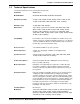
Appendix C - AT Command Summary Appendix C - AT Command Summary Command Values Description AT Attention Code that precedes most command strings except A/, A: and Escape Codes. RETURN Pressing RETURN key executes most commands. $ This symbol placed in dialing string enables the modem to detect AT&T's "call card" tones for accessing user's calling card to originate an on-line connection. A Answer call, even if no ring present. Repeat last command. (Do not precede this command with AT.
Appendix C - AT Command Summary Command Values Description DsNd s = phone # Store telephone number. To store, phone d = 0 thru 9 number ”s“ is entered and followed by N and then Directory Number “d.” &Dn n = 0 thru 3 &D0 DTR is ignored &D1 means modem returns to command mode. &D2 lets modem react to DTR normally. &D3 causes modem to reset to modem default parameters. * %DFn n = 0 or 1 * %DF0 Line Probe Data in Graph Format. %DF1 Line Probe Data in Table Format.
Appendix C - AT Command Summary &Fn n = 0, 8 or 9 * $Fn n = 0 or 1 * $FCn (MT2834BL) n = 0 or 1 * * &F loads factory default values from ROM. &F8 reads factory default values and switch settings when &F is issued. &F9 reads parameters stored in non-volatile memory when &F is issued. $F0 means do not fall back to normal connect if CR received. $F1 means fall back to normal connect if CR received. $FC0 means no transmit of 5 second 2100Hz signal. $FC1 transmits 5 second 2100Hz signal.
Appendix C - AT Command Summary $MBn n = speed * * $MB75 selects CCITT V.23 mode. $MB300 selects 300 bps on-line. $MB1200 selects 1200 bps on-line. $MB2400 selects 2400 bps on-line. $MB4800 selects 4800 bps on-line. $MB9600 selects 9600 bps on-line. $MB14400 selects 14400 bps on-line $MB19200 selects 19200 bps on-line $MB28800 selects 28800 bps on-line $MB33600 selects 33600 bps on-line &Mn n = 0 or 1 Nd d = 0 thru 9 Dial stored telephone number “d” (Do not include the letter D in this command.
Appendix C - AT Command Summary $SBn n = speed * &SFn n = 0 or 1 &Sn n = 0, 1 or 2 * * $SPn n = 0 or 1 * T &Tn n = 4 or 5 n = 0 or 1 * Un n = 0, 1, 2, or 3 $VDn n= 0 or 1 Vn n = 0 or 1 &S0 forces Data Set Ready On. &S1 lets Data Set Ready act normally. &S2 Data Set Ready drop is regulated by S24 on disconnect. $SP0 disables UUCP Spoofing $SP1 enables UUCP Spoofing &T4 means Enable Response to Request for Remote Digital Loopback.
Appendix C - AT Command Summary Xn n = 0,1,2,3 or 4 * X0 selects Basic Result Codes (w/o CONNECT 1200, CONNECT 2400). X1 selects Extended Result Codes (w/CONNECT 1200, CONNECT 2400). X2 selects Standard AT Command set with NO DIAL TONE. X3 selects Standard AT Command set with BUSY. X4 selects Standard AT Command set with NO DIAL TONE and BUSY. #Xn n= 0 or 1 * #X0 selects single XOFF character sent until XON level returns. #X1 selects multiple XOFF characters after buffer level is full.
Appendix C - AT Command Summary Callback Security/Remote Configuration Command Summary Command Description #DBn #DB0 disables Callback Security and answering Yes to the prompt turns off Callback Security and erases stored phone numbers and passwords. Answering No to the prompt aborts the command. #DB1 activates remote and local password security. #DB2 activates remote password security. #CBNyyxxxxxx Callback password with xxxxxx being callback password and yy being the memory location.
Appendix C - AT Command Summary Password Command Summary Command Description #Ixxxxxxxxxx Login Password is any keyboard characters (x) (upper/lower case sensitive), minimum 6 and maximum 10 characters. The default Login Password is #IMULTI-TECH. #Syyyyyyyyyy Setup Password is any keyboard characters (y) (upper/lower case sensitive), minimum 6 and maximum 10 characters. The default Setup Password is #SMODEMSETUP. V.
Appendix D - V.25bis Operation Appendix D - V.25bis Operation Chapter 4 described a set of commands which let the modem dial, hang-up, and be configured for various applications. However, these commands, the AT command set, are only functional when the DTE transmits data asynchronously. That is, they cannot be used with synchronous equipment such as that found in IBM's Binary Synchronous Communications (BSC) and Synchronous Data Link Control (SDLC)* environments. The ITU V.
Appendix D - V.25bis Operation V.25bis Set-Up and Initialization Before you operate your modem in the V.25bis mode, you need to make sure it is set up properly (various RS-232 lines such as DSR and CTS act as specified in the V.25bis standard). Setup involves proper DIP-Switch settings and soft-switches (software controlled conditions). V.
Appendix D - V.25bis Operation V.25bis Responses (Result Codes) When in V.25bis mode (the AT$V1 command executed), your modem provides you with several responses which can help you follow the progress of V.25bis operations. These are similar to the Result Codes associated with AT Command mode operation. The V.25bis responses are in the form of threecharacter mnemonics as listed below: INC VAL DLCt CFlrr LSNmm;dd...dd LSDmm;dd...dd LSFmm;dd...dd CON ssss Incoming Call (same as RING indicator) A valid V.
Appendix D - V.25bis Operation Dial Phone Number Provided (CRN) Command The CRN command permits the dialing of the phone number immediately following it (from the command line). It is similar to the D command, except that the number is first checked against the Delayed Number and Forbidden Number list. If permitted, depending on the country regulations in effect, the number will then be dialed. For example, if you enter CRN7859875 and hit RETURN, your modem will check the two lists.
Appendix D - V.25bis Operation ITU V.25bis Country Specific Information Due to the flexibility of the V.25bis standard, each country may establish specific regulations governing the way operations are handled. The purpose of this document is to detail each country's specific regulations that affect operation of V.25bis in Multi-Tech modems. 1. Italy a) Command/Indication modifications 1.
Appendix D - V.25bis Operation 5. Belgium a) b) c) 6. Singapore a) b) Command/Indication modification (none) Delay and Forbidden list behavior 1. 1 min. delay between calls 2. After 4 retries, the number is put on the forbidden list 3. The number remains on the forbidden list for 1 hour after entry to forbidden list 4. Delayed and Forbidden Numbers lists are checked when dialing in AT command mode. If dialing is not possible then No Carrier is the response. Auto-Answer behavior 1.
Appendix E - MultiModemBA/BL Cables Appendix E - MultiModemBA Cables These cables connect your modem to your terminal or computer’s serial port. 25-PIN DTE Connector TD 25-PIN DCE Device 2 2 TD RD 3 3 RD RTS 4 4 RTS CTS 5 5 CTS DSR 6 6 DSR GND 7 7 GND CD 8 8 DTR20 20 DTR RI 22 22 CD RI Figure E-1. RS232 Cable (IBM PC) 1 2 RED (Tip) 3 4 5 GREEN (Ring) 6 To Terminal Block Screws (Transmit and Receive) RJ-11 Type Modular Plug Figure E-2.
Appendix F - Regulatory Information Appendix F - Regulatory Information FCC Part 15 This equipment has been tested and found to comply with the limits for a Class B digital device, pursuant to Part 15 of the FCC Rules. These limits are designed to provide reasonable protection against harmful interference in a residential installation.
Appendix F - Regulatory Information Canadian Limitations Notice Notice: The ringer equivalence number (REN) assigned to each terminal device provides an indication of the maximum number of terminals allowed to be connected to a telephone interface. The termination on an interface may consist of any combination of devices subject only to the requirement that the sum of the ringer equivalence numbers of all the devices does not exceed 5. Notice: The Industry Canada label identifies certificated equipment.
Appendix F - Regulatory Information 7. 8. Some parameters required for compliance with Telecom’s Telepermit requirements are dependent on the equipment (PC) associated with this device.
Appendix G – WEEE Statement Appendix G – WEEE Statement (Waste Electrical and Electronic Equipment) Introduction The WEEE directive places an obligation on EU-based manufacturers, distributors, retailers and importers to take-back electronics products at the end of their useful life. A sister Directive, ROHS (Restriction of Hazardous Substances) complements the WEEE Directive by banning the presence of specific hazardous substances in the products at the design phase.
Index Index Symbols 2 Wire/ 4 Wire Operation .................................... 83 2 Wire/4 Wire Operation ..................................... 83 A Abort Timer ......................................................... 60 Answer Mode ..................................................... 47 Answer/Originate - Voice/Data Toggle Switch .... 20 AS/400 Mode ..................................................... 79 ASCII code .........................................................
Index Enable/Suppress Responses .............................. 78 Erase Callback Password (#RCBNxx) ................ 74 Erase Callback Phone Number (#RDNxx) ........... 74 Error Correction .................................................... 9 Escape Code Character ...................................... 59 Escape Sequence Options (%E) ........................ 56 Escape Sequences (+++AT) ...................... 56 Examples of Assigning Values ........................... 66 Examples of Reading Values ....
Index Parity .................................................................. 18 Parity Selection (#P) ........................................... 51 Password Command Summary ........................ 106 Pause Time for Comma ...................................... 60 PBX/CBX Disconnect Drop Time for DSR/CTS/CD63 PBX/CBX systems ............................................. 63 Power .................................................................. 10 Power supply ..........................................