
User Guide Data/Fax Modems MT2834BA/MT2834BL

77
Chapter 8 - Dip-Switch Settings
Multi-Tech Systems, Inc. MT2834BA/BL Series User Guide
8.1 Introduction
There are several DIP-Switch options on the modem’s printed circuit (PC) board. The DIP-Switches
are accessible through a cut-out on the side of the modem. This chapter explains the modem’s
printed-circuit board options. Sixteen DIP-Switch settings and the modem's speaker volume control
are explained in detail, including all default settings.
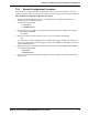
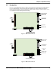
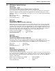
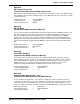
OPEN
13 14 15 16
OPEN
123456789101112
LED
Indicators
16-position DIP-switch
Phone Jack
Line Jack
RS-232/V.24
Connector
Power Jack
Power Switch
Figure 8-1. MT2834BA PC Board
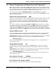
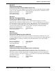
Phone Jack
Dial-up Jack
Lease-Line
Jack
RS-232/V.24
Connector
Power Jack
Power Switch
LED
Indicators
OPEN
13 14 15 16
OPEN
123456789101112
16-position DIP-switches
Figure 8-2. MT2834BL PC Board