SocketModemÔ Embedded Modem MT5600SMI Family MT5600SMI-32 MT5600SMI-L32 MT5600SMI-P32 MT5600SMI-34 MT5600SMI-L34 MT5600SMI-XL34 MT5600SMI-P34 MT5600SMI-PL34 MT5600SMI-92 MT5600SMI-L92 MT5600SMI-XL92 MT5600SMI-P92 MT5600SMI-PL92 Developer’s Guide
Copyright and Technical Support SocketModemÔ Developer's Guide MT5600SMI (MT5600SMI-32, MT5600SMI-L32, MT5600SMI-P32, MT5600SMI-34, MT5600SMI-L34, MT5600SMI-XL34, MT5600SMI-P34, MT5600SMI-PL34, MT5600SMI-92, MT5600SMI-L92, MT5600SMI-XL92, MT5600SMI-P92, MT5600SMI-PL92) PN S000306A, Version A Copyright This publication may not be reproduced, in whole or in part, without prior expressed written permission from Multi-Tech Systems, Inc. All rights reserved. Copyright © 2002-2003, by Multi-Tech Systems, Inc.
Table of Contents Contents Chapter 1 – Product Description and Specifications................................................................................ 5 Introduction ................................................................................................................................................ 5 Product Description ................................................................................................................................... 5 Features.............................
Table of Contents Compatibility Commands ..................................................................................................................... 70 FastConnect Commands ..................................................................................................................... 71 V.92 +P and –Q Commands................................................................................................................ 71 S-Registers .........................................................
Chapter 1 – Product Description and Specifications Chapter 1 – Product Description and Specifications Introduction The Multi-Tech SocketModem creates communication-ready devices by integrating data functionality into a single product design. The SocketModem is a space-efficient (1" × 2.5"), embedded modem that provides V.92 or V.34/33.6K data communication. The complete, ready-to-integrate modem dramatically reduces development time and costs for system designers.
Chapter 1 – Product Description and Specifications Developer's Kit A Developer's Kit is available. The serial kit allows you to plug in the SocketModem and use it as a serial modem for testing, programming, and evaluation. The parallel kit turns the parallel module into an ISA modem. Each kit includes one SocketModem, one development board with an RS-232 DB-25 connector, wall power adapter, RJ-11 jack, and RS-232 cable.
Chapter 1 – Product Description and Specifications Technical Specifications The SocketModem meets the following specifications: Data Format Serial or parallel interface Data V.92; V.90, V.34, V.32bis, V.32, V.22bis, V.22, V.23, V.21,Bell 212A & Bell 103 Error Correction V.42 (LAP-M or MNP 2–4) Data Compression V.42bis, MNP 5 Fax V.17, V.29, V.27ter, V.21 ch.2 Class 1 and 1.
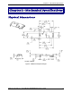
Chapter 2 – Mechanical Specifications Chapter 2 – Mechanical Specifications Physical Dimensions Figure 2–1. Maximum Component Height Multi-Tech Systems, Inc.
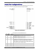
Chapter 2 – Mechanical Specifications Serial Pin Configurations The serial interface use an 16-pin interface to provide an on-board DAA with tip and ring connections, audio circuit for call-progress monitoring and serial interface via logic level signals. Figure 2–2. Serial SocketModems Pins Available with or without LED Pins Pin Descriptions for Serial SocketModem Devices Pin # Signal Name I/O Type 1 Tip I/O Tip Signal from Telco. Tip connection to the phone line (RJ11 Pin 3).
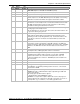
Chapter 2 – Mechanical Specifications Pin # Signal Name I/O Type Description 31 DTRIND DTR LED. Output from 74AC05 with 1500 Ohms pull-up. 32 TXIND TX LED. Output from 74AC05 with 1500 Ohms pull-up. 33 –RTS I Request to Send. RTS signal is used for hardware flow control. 34 –RXD O Received Data. Used to send data received from the telephone line and also modem responses to the DTE. Modem response take priority over incoming data.
Chapter 2 – Mechanical Specifications Parallel Pin Configurations The parallel interface SocketModem uses a 22-pin interface to provide an on-board DAA with tip and ring connections, audio circuit for call-progress monitoring, and parallel interface. Figure 2–3.
Chapter 2 – Mechanical Specifications Pin # Signal Name I/O Description 32 –WT I Host Bus Write. When low, allows host to write to SocketModem. 33 –RD I Host Bus Read. When low, allows host to read from SocketModem.
Chapter 3 – Electrical Characteristics Chapter 3 – Electrical Characteristics Handling Precautions All electronic devices should be handled with certain precautions to avoid damage due to the accumulation of static charge. Although input protection circuitry has been incorporated into the devices to minimize the effect of this static buildup, proper precautions should be taken to avoid exposure to electrostatic discharge during handling and mounting. I/O Electrical Characteristics 3.
Chapter 3 – Electrical Characteristics 5V Serial SocketModem 5 Vdc Characteristics (TA = 0 °C to 50 °C; VDD = 5 V ± 0.25 V) Digital Inputs –DTR (40), –TXD (35), –RTS (33), –RESET (24) VDDMAX = Input High Min 3.5 V 5.25 V Input Low Max .8 V Digital Outputs Output High Output Low Current Drive –DCD (39), –CTS (38), –DSR (37), –RI (36), –RXD (34) Min 4 V Max 0.5 V 15 ma Digital Input Capacitance 5 PF 5V Parallel SocketModem 5 Vdc Characteristics (TA = 0 °C to 50 °C; VDD = 5 V ± 0.25 V) VDDMAX = 5.
Chapter 3 – Electrical Characteristics Current and Power Requirements Mode Typ. Current (mA) Max. Current (mA) Typ. Power (mW) Max. Power (mW) 0.38 0.41 +3.3 V Configuration (VDD = +3.3 V) Normal Mode (Serial interface) 115 116 +5 V Configuration (VDD = +5 V) Normal Mode (Serial interface) 117 118 0.58 Normal Mode (Parallel interface) 117 118 0.58 Test conditions: For Pin 61 = +5 V, VDD = +5 V for typical values; VDD = +5.25 V for maximum values. For Pin 61 = +3.3 V, VDD = +3.
Chapter 3 – Electrical Characteristics Parallel Host Bus Timing Parallel Host Bus Timing Table Symbol t AS AH t CS t CH t RD t DD t DRH t t Parameter Min READ (See Notes) Address Setup 5 Address Hold 10 Chip Select Setup 0 Chip Select Hold 10 RD Strobe Width 45 Read Data Delay Read Data Hold 5 WRITE (See Notes) Address Setup 5 Address Hold 15 Chip Select Setup 0 Chip Select Hold 10 WT Strobe Width 75 Write Data Setup (see Note 4) Write Data Hold (see Note 5) 5 Max Units 25 - ns ns ns ns ns ns ns n
Chapter 3 – Electrical Characteristics Parallel Host Bus - Read Parallel Host Bus - Write Multi-Tech Systems, Inc.
Chapter 4 – SocketModem Parallel Interface – A Programmer's Description Chapter 4 – SocketModem Parallel Interface – A Programmer’s Description SocketModem Parallel Interface The modem supports a 16550A interface in parallel interface versions. The 16550A interface can operate in FIFO mode or non-FIFO mode. Non-FIFO mode is the same as the 16450 interface operation. FIFO mode’s unique operations are described in this chapter.
Chapter 4 – SocketModem Parallel Interface – A Programmer's Description Table 4–1. Parallel Interface Registers Register No.
Chapter 4 – SocketModem Parallel Interface – A Programmer's Description Register Signal Definitions IER – Interrupt Enable Register (Addr = 1, DLAB = 0) The IER enables five types of interrupts that can separately assert the HINT output signal (Table 4– 2.). A selected interrupt can be enabled by setting the corresponding enable bit to a 1, or disabled by setting the corresponding enable bit to a 0.
Chapter 4 – SocketModem Parallel Interface – A Programmer's Description FCR – FIFO Control Register (Addr = 2, Write Only) The FCR is a write-only register used to enable FIFO mode, clear the RX FIFO and TX FIFO, enable DMA mode, and set the RX FIFO trigger level. Bits 7-6 RX FIFO Trigger Level FCR7 and FCR6 set the trigger level for the RX FIFO (Receiver Data Available) interrupt.
Chapter 4 – SocketModem Parallel Interface – A Programmer's Description IIR – Interrupt Identifier Register (Addr = 2) The Interrupt Identifier Register (IIR) identifies the existence and type of up to five prioritized pending interrupts. Four priority levels are set to assist interrupt processing in the host. The four levels, in order of decreasing priority, are Highest: Receiver Line Status, 2: Receiver Data Available or Receiver Character Timeout. 3: TX Buffer Empty, and 4: Modem Status.
Chapter 4 – SocketModem Parallel Interface – A Programmer's Description LCR – Line Control Register (Addr = 3) The Line Control Register (LCR) specifies the format of the asynchronous data communications exchange. Bit 7 Divisor Latch Access Bit (DLAB) This bit must be set to a 1 to access the Divisor Latch Registers during a read or write operation. It must be reset to a 0 to access the Receiver Buffer, the Transmitter Buffer, or the Interrupt Enable Register.
Chapter 4 – SocketModem Parallel Interface – A Programmer's Description MCR – Modem Control Register (Addr = 4) The Modem Control Register (MCR) controls the interface with modem or data set. Bit 7-5 Not used Always 0 Bit 4 Local Loopback When this bit is set to a 1, the diagnostic mode is selected and the following occurs: 1. Data written to the Transmit Buffer is looped back to the Receiver Buffer. 2.
Chapter 4 – SocketModem Parallel Interface – A Programmer's Description LSR – Line Status Register (Addr = 5) This 8-bit register provides status information to the host concerning data transfer. Bit 7 RX FIFO Error In the 16450 mode, this bit is not used and is always 0. In the FIFO mode, this bit is set if there are one or more characters in the RX FIFO with parity error, framing error, or break indication detected.
Chapter 4 – SocketModem Parallel Interface – A Programmer's Description MSR – Modem Status Register (Addr = 6) The Modem Status Register (MSR) reports current state and change information of the modem. Bits 4-7 supply current state, and bits 0-3 supply change information. The change bits are set to a 1 whenever a control input form the modem changes state from the last MSR read by the host. Bits 0-3 are reset to 0 when the host reads the MSR or upon reset.
Chapter 4 – SocketModem Parallel Interface – A Programmer's Description SCR – Scratch Register (Addr = 7) The Scratchpad Register is a read-write register at location 7. This register is not used by the modem and can be used by the host for temporary storage.
Chapter 4 – SocketModem Parallel Interface – A Programmer's Description Receiver FIFO Interrupt Operation Receiver Data Available Interrupt When the FIFO mode is enabled (FCR0 = 1) and receiver interrupt (RX Data Available) is enabled (IER0 = 1), receiver interrupt operation is as follows: 1. The Receiver Data Available Flag (LSR0) is set as soon as a received data character is available in the RX FIFO. LSR0 is cleared when RX FIFO is empty. 2.
Chapter 5 – AT Commands, S-Registers, and Result Codes Chapter 5 – AT Commands, SRegisters, and Result Codes Introduction The AT commands are used to control the operation of your modem. They are called AT commands because the characters AT must precede each command to get the ATtention of the modem. AT commands can be issued only when the modem is in command mode or online command mode. The modem is in command mode whenever it is not connected to another modem.
Chapter 5 – AT Commands, S-Registers, and Result Codes Data Commands The modem will respond to the commands detailed below. Parameters applicable to each command are listed with the command description. Generic Modem Control Commands Command: Z Description: Causes the modem to perform a soft reset and restore (recall) the configuration profile. If no value is specified, zero is assumed. None Number corresponding to the selected profile: Z0 Soft reset and restore stored profile 0.
Chapter 5 – AT Commands, S-Registers, and Result Codes Command: \N Description: Default: Defined Values: Result Codes: Command I Description: Identification Causes the modem to reports the requested result according to the command parameter. 4 I0 Reports product code (e.g., 56000). I1 Reports the least significant byte of the stored checksum (e.g., 12AB). I2 Checks ROM and verifies the checksum. Reports OK or ERROR. I3 Reports ROM Code Revision-Modulation (e.g., 2109-V90).
Chapter 5 – AT Commands, S-Registers, and Result Codes Command +GMM Request Model Identification Description: Typical Response: Causes the modem to report the modem product. +GMM: V92 Command: Request Revision Identification +GMR Description: Typical Response: Command: +GCAP Description: Example Responses: Command: +GCI Description: Default: Report Commands: Command: Description: Default: Values: Result Codes: &F Causes the modem to report the modem version, revision level, or date.
Chapter 5 – AT Commands, S-Registers, and Result Codes Command: &T Description: The modem will perform the local analog loopback test if &T1 is selected. The test can be run only when in an asynchronous operation in non-errorcorrection mode (normal), e.g., AT&Q6. To terminate the test in progress, the escape sequence must be entered first. None &T0 Terminates test in progress. Clears S16. &T1 Initiates local analog loopback, V.54 Loop 3. Sets S16 bit 0.
Chapter 5 – AT Commands, S-Registers, and Result Codes Command %8 Description: Sets and stores Vendor ID and product number for serial Plug and Play and for ISA Plug and Play which use the Conexant 11596 Plug and Play device. Applicable to Desktop configuration only.
Chapter 5 – AT Commands, S-Registers, and Result Codes 7. After the FLM has been loaded, if uploading new firmware to the modem, perform an XMODEM upload of the new modem firmware hex file (e.g., 206s4712.S37) from the host computer to the modem RAM using industry standard communications software or an equivalent process. If downloading existing firmware from the modem, using an industry standard communications software or equivalent, put the host PC in XMODEM receive mode. 8.
Chapter 5 – AT Commands, S-Registers, and Result Codes DTE-Modem Interface Commands The parameters defined in this section control the operation of the interface between the DTE and modem. Command: E Description: The modem enables or disables the echo of characters to the DTE. The parameter value, if valid, is written to S14 bit 1. 1 E0 Disables command echo. E1 Enables command echo.
Chapter 5 – AT Commands, S-Registers, and Result Codes Command: Description: Default: Defined Values: Result Codes: X Extended Result Codes Selects the subset of the result code messages used by the modem to inform the DTE of the results of commands. Blind dialing is enabled or disabled by country parameters. If the user wishes to enforce dial tone detection, a "W" can be placed in the dial string (see D command). The information below is based upon the default implementation of the X results table.
Chapter 5 – AT Commands, S-Registers, and Result Codes Command: &C Description: The modem controls the RLSD output in accordance with the parameter supplied. The parameter value, if valid, is written to S21 bit 5. 1 0 RLSD remains ON at all times. 1 RLSD follows the state of the carrier.
Chapter 5 – AT Commands, S-Registers, and Result Codes Command: &R RTS/CTS Option Description: This selects how the modem controls CTS. CTS operation is modified if hardware flow control is selected (see &K command). The parameter value, if valid, is written to S21 bit 2. None &R0 In sync mode, CTS tracks the state of RTS; the RTS-to-CTS delay is defined by S26. In async mode, CTS is normally ON and will turn OFF only if required by flow control.
Chapter 5 – AT Commands, S-Registers, and Result Codes Command: +IFC DTE-Modem Local Flow Control Description: This extended-format compound parameter controls the operation of local flow control between the DTE and the modem during the data state when V.42 error control is used, or when fallback to non-error control mode is specified to include buffering and flow control. It accepts two numeric subparameters.
Chapter 5 – AT Commands, S-Registers, and Result Codes Call Control Commands Command: Description: Defined Values: D Dial Directs the modem to go on-line, dial according to the string entered and attempt to establish a connection. If no dial string is supplied, the modem will go on-line and attempt the handshake in originate mode. Note: If the ATD command is issued before the S1 register has cleared, the modem will respond with the NO CARRIER result code.
Chapter 5 – AT Commands, S-Registers, and Result Codes of silence before the expiration of the call abort timer (S7), the modem will terminate the call attempt with a NO ANSWER message. If busy detection is enabled, the modem may terminate the call with the BUSY result code. If answer tone arrives during execution of this parameter, the modem handshakes. & Wait for credit card dialing tone before continuing with the dial string.
Chapter 5 – AT Commands, S-Registers, and Result Codes Command: A Description: Command: The modem will go off-hook and attempt to answer an incoming call if correct conditions are met. Upon successful completion of answer handshake, the modem will go on-line in answer mode. This command may be affected by the state of Line Current Sense, if enabled. (Most countries do not require Line Current Sense.) Operation is also dependent upon +FCLASS command and country-specific requirements.
Chapter 5 – AT Commands, S-Registers, and Result Codes Command: L Description: Default: Defined Values: Result Codes: Command: M Description: Result Codes: &G Description: Result Codes: Description: Default: Defined Values: Result Codes: Select Guard Tone Causes the modem to generate the guard tone selected by this command (DPSK modulation modes only). The parameter value, if valid, is written to S23 bits 6 and 7. This command may not be permitted in some countries. 0 &G0 Disables guard tone.
Chapter 5 – AT Commands, S-Registers, and Result Codes Command: Description: Result Code: Example: &V Display Current Configuration and Stored Profiles Reports the current (active) configuration, the stored (user) profiles, and the first four stored telephone numbers. The stored profiles and telephone numbers are not displayed if the NVRAM is not installed or is not operational as detected by the NVRAM test during reset processing.
Chapter 5 – AT Commands, S-Registers, and Result Codes Command: Description: &V1 Display Last Connection Statistics Displays the last connection statistics in the following format (shown with typical results): TERMINATION REASON LOCAL REQUEST LAST TX rate 26400 BPS HIGHEST TX rate 26400 BPS LAST RX rate.
Chapter 5 – AT Commands, S-Registers, and Result Codes Command: \V Description: Default: Defined Values: Command: Enables or disables the single-line connect message format as follows: None \V0 Connect messages are controlled by the command settings X, W, and S95. \V1 Connect messages are displayed in the single line format described below subject to the command settings V (Verbose) and Q (Quiet).
Chapter 5 – AT Commands, S-Registers, and Result Codes Command: –STE= Description: Set Telephony Extension Enables/disables Line-In-Use, Extension Pickup, and Remote Hangup detection features. Note: Additional hardware may be required to support these features. The corresponds to the selected bit-mapped options. The bit fields are defined as follows: Bit 0 Line-In-Use detection enable/disable. Bit 1 Extension Pickup detection enable/disable. Bit 2 Remote Hangup detection enable/disable.
Chapter 5 – AT Commands, S-Registers, and Result Codes Case 2: Telephone Line is in Use but Disconnected If an ATDT, ATDP or ATDL is issued while Line-In-Use detection is enabled and the telephone line is NOT in use, the modem will go offhook after a short pause, then respond with CONNECT or NO CARRIER message.
Chapter 5 – AT Commands, S-Registers, and Result Codes An extension is off-hook but there is silence on the line and the modem tries to dial AT-STE=3 ATDT555-1212 Modem goes off-hook NO DIAL TONE Modem is connected in data mode and remote modem goes on-hook AT-STE=4 ATDT555-1212 CONNECT NO CARRIER Remote modem drops line ATS86=? 025 Modem is in answer machine mode and an extension goes off-hook AT-STE=2 AT+FCLASS=8 OK h Local handset on-hook R Ring AT+VLS=1 OK AT+VSM=1,7200,0,0 AT+VTX Starts to p
Chapter 5 – AT Commands, S-Registers, and Result Codes Modulation Control Commands Command: Description: Syntax: +MS Modulation Selection This extended-format compound parameter controls the manner of operation of the modulation capabilities in the modem. It accepts six subparameters. +MS=[[,[,[, [, [,]]]]]] Where possible , , , , and values are listed in Table 5-3.
Chapter 5 – AT Commands, S-Registers, and Result Codes Report Commands: Result Code: and Numeric values which specify the lowest () and highest () rate at which the modem may establish a transmit connection. Non-zero values for this subparameter are decimal encoded, in units of bit/s. The possible values for each modulation are listed in Table 5-3.
Chapter 5 – AT Commands, S-Registers, and Result Codes Command: +MR Description: Default: Defined Values: Report Commands: Command: Description: Default: Defined Values: Result Codes: %E Modulation Reporting Control This extended-format numeric parameter controls whether or not the extended-format +MCR: and +MRR: intermediate result codes are transmitted from the modem to the DTE.
Chapter 5 – AT Commands, S-Registers, and Result Codes Command: %U Description: Selects µ-Law or A-Law codec type for V.90 and 56K modulation. This command also stores the selected setting directly to NVRAM. Default value is country specific 0 Selects µ-Law. 1 Selects A-Law.
Chapter 5 – AT Commands, S-Registers, and Result Codes Error Control Commands Command: Description: Default: Defined Values: Examples: +ES Error Control and Synchronous Mode Selection This extended-format command specifies the initial requested mode of operation when the modem is operating as the originator.
Chapter 5 – AT Commands, S-Registers, and Result Codes +ES=6,,8 +ES=3 +ES=,,2 +ES=3,,2 Report Commands: +ES? +ES=? Command: +EB Description: Default: Defined Values: Report Commands: Command: +ESR Description: Report Commands: Command: +EFCS Description: Defined Values: Report Commands: Enable V.80 Synchronous Access Mode. Enable V.42 with Detection Phase originator. Disable V.80 Synchronous Access Mode originator. Allow LAPM, MNP, or Normal Mode connection answerer. Disable V.
Chapter 5 – AT Commands, S-Registers, and Result Codes Command: +ER Description: Default: Defined Values: Report Commands: Command: +ER: Report the Current Error Control Description: The +ER: reported represents the current (negotiated or renegotiated) modem-modem error control type.
Chapter 5 – AT Commands, S-Registers, and Result Codes Command: \B Description: In non-error correction mode, the modem will transmit a break signal to the remote modem with a length in multiples of 100 ms according to parameter specified. If a number in excess of 9 is entered, 9 is used. The command works in conjunction with the \K command. In error correction mode, the modem will signal a break through the active error correction protocol, giving no indication of the length.
Chapter 5 – AT Commands, S-Registers, and Result Codes Command: Description: Defined Values: Result Codes: -K MNP Extended Services Enables or disables conversion of a V.42 LAPM connection to an MNP 10 connection. The parameter value, if valid, is written to S40 bits 0 and 1. -K0 Disables V.42 LAPM to MNP 10 conversion. (Default.) -K1 Enables V.42 LAPM to MNP 10 conversion. -K2 Enables V.42 LAPM to MNP 10 conversion; inhibits MNP Extended Services initiation during V.42 LAPM answer mode detection phase.
Chapter 5 – AT Commands, S-Registers, and Result Codes Data Compression Commands This section contains parameters to condition modem use of standard ITU-T V.42bis Data Compression Procedures. Command: +DS Description: Defined Values: Report Commands: Command: Description: Defined Values: +DS44 Data Compression This extended-format compound parameter controls the V.42bis data compression function if provided in the modem.
Chapter 5 – AT Commands, S-Registers, and Result Codes Report Commands: Command: +DR Description: Defined Values: Report Commands: Intermediate Result Code: Decimal number 256 to 2048 that specifies the maximum number of codewords which should be negotiated in the transmit direction. (Default = 2048.) Decimal number 256 to 2048 that specifies the maximum number of codewords which should be negotiated in the receive direction. (Default = 2048.
Chapter 5 – AT Commands, S-Registers, and Result Codes The format of this result code is: Defined Values: V42B V42B Example: Command: Description: Defined Values: Result Codes: An alphanumeric code corresponding to the selected option: NONE Data compression is not in use. V.42bis is in use in both directions. RD V.42 bis is in use in receive direction only V42B TD V.42 bis is in use in transmit direction only V44 V.44 is in use in both directions V44 RD V.
Chapter 5 – AT Commands, S-Registers, and Result Codes V.8/V.8bis Commands Command: +A8E Description: Defined Values: Default values: Report Commands: V.8 and V.8bis Operation Controls This command is defined for two conditions: as a parameter while the modem is on-hook, and as an action command while the modem is offhook. If enabled, V.8 negotiation does not preclude simultaneous implementation of other negotiation means (e.g., V.8bis, V.18, V.32bis Annex A).
Chapter 5 – AT Commands, S-Registers, and Result Codes Command: Description: Defined Values: Example: +A8I: CI Signal Indication This indication is issued by an answering modem, if +A8E, .0, to indicate detection of a V.8 CI signal, and report the recovered Call Function octet(s). A hexadecimal code octet representation of the Call Function octet(s). +A8I:0 indicates that the modem timed out waiting for CI. +A8I:0 The modem timed out waiting for CI. +A8I:X YYY Multi-Tech Systems, Inc.
Chapter 5 – AT Commands, S-Registers, and Result Codes Diagnostic Commands Command: Description: #UD Last Call Status Report #UD is an action command requesting logged operation events reporting. It does not take parameters and must be the last command in the command line. The modem logs aspects of their operation for each call, and saves these results until cleared by one of the following events: Power off. Hard reset (e.g., negate DTR with &D3 set; reset button). Soft reset = ATZ or AT&F.
Chapter 5 – AT Commands, S-Registers, and Result Codes Unless otherwise noted, all values are hexadecimal numbers. Any numeric values from tables in ITU V.58 are converted to hexadecimal. Multi-digit values are reported MSD first. Leading 0’s may be deleted. See examples in Table 5-13. Monitoring an Active Connection This command is intended for use after call termination. However, codes are defined so that a modem can respond before the first call is placed, and during a call for live monitoring purposes.
Chapter 5 – AT Commands, S-Registers, and Result Codes 55 56 57 58 59 60 61 0-FFFF 0-FFFFFFFF 0-FFFFFFFF 0-FFFF 0-FFFF Table 5-12 0-FF Call Received characters lost (data overrun errors to DTE) Transmit I- Frame count, if error control protocol running Received I-Frame count, if error control protocol running Transmit I-Frame error count, if error control protocol running Received I- Frame error count, if error control protocol running Termination Cause Waiting event count Table 5-5.
Chapter 5 – AT Commands, S-Registers, and Result Codes Table 5-10. errorControl Active from 3.5.2/V.58 Value Description 0 1 2 80 Disable/none V.42 LAPM V.42 Alternative protocol (MNP™) MNP10™ Table 5-11. compressionActive from 3.2.2/V.58 Value Description 0 1 80 None V.42bis and V.44 MNP5™ Table 5-12. callCleared codes from 3.6.4/V.
Chapter 5 – AT Commands, S-Registers, and Result Codes Example Modem Response and Usage Example #UD commend response are shown in Table 5-13. Table 5-13. Completed Data Call, with some errors and rate retrain during the call Modem Response Line Description DIAG <2A4D3263 0=09> DIAG <2A4D3263 1=06 2=0 3=0> This is version 0.9 Data Answer signal detected; Data only; Character async V.8 Call Menu indicates: V.
Chapter 5 – AT Commands, S-Registers, and Result Codes Compatibility Commands Command: &L Description: Requests leased line or dial-up operation. This command is provided for compatibility only; no mode change is performed, dial-up operation continues. The OK response is returned for a valid parameter, but no other action is performed. The parameter value, if valid, is written to S27 bit 2. &L0 Requests dial-up operation. Dial-up operation continues.
Chapter 5 – AT Commands, S-Registers, and Result Codes FastConnect Commands Command: $F Description: FastConnect Control Allows configuring of the client modem to connect to a central site modem that supports non-standard V.22 and V.22 bis FastConnect protocols. Specifies the initial requested mode of operation when the modem is operating as the originator.
Chapter 5 – AT Commands, S-Registers, and Result Codes Command: +PMHR Initiate Modem-on-Hold Description: Requests the modem to initiate or to confirm a modem-on-hold procedure. The modem will return ERROR if modem-on-hold is not enabled or if the modem is in an idle condition. The modem will return the string response +PMHR: where is a decimal value corresponding to the status of the modem's hold exchange procedure as defined below.
Chapter 5 – AT Commands, S-Registers, and Result Codes Command: +PIG Description: Defined Values: Result Codes: Report Commands: Command: +PMHF Description: V.92 Modem-on-Hold Hook Flash Causes the modem to initiate the flash hook sequence when in the modem-on- hold procedure. This enables switching to the second call (incoming or outgoing). This command applies only to V.92 modem-on-hold. There are no parameters associated with this command. OK When the modem completes the flash hook sequence.
Chapter 5 – AT Commands, S-Registers, and Result Codes Command: +PSS Description: Defined Values: Result Codes: Report Commands: Command: -QCPC Description: Causes a calling modem to force either a V.92 short or full startup sequence as defined by the +PQC command on the next and subsequent connections. +PSS0 The modems decide whether or not to use the short startup procedures. The short startup procedures can only be used if enabled by the +PQC command. (Default.) +PSS1 Reserved.
Chapter 5 – AT Commands, S-Registers, and Result Codes S-Registers Certain modem values, or parameters, are stored in memory locations called S-registers. Use the S command to read or to alter the contents of S-registers (see previous section). * Register value may be stored on one of two user profiles with the command &W. Register Unit Range Default Description S0 1 ring 0–255 0 Number of Rings to Auto-Answer: Sets the number of rings until the modem answers. ATS0=0 disables autoanswer completely.
Chapter 5 – AT Commands, S-Registers, and Result Codes Register Unit Range Default Description S9 0.1 s 1–255 6 Carrier Detect Response Time: Supported for backward compatibility only. No value can be written. Responds with default value. * S10 0.1 s 1–255 14 Lost Carrier to Hang Up Delay: Sets the length of time, in tenths of a second that the modem waits before hanging up after a loss of carrier. This allows for a temporary carrier loss without causing the local modem to disconnect.
Chapter 5 – AT Commands, S-Registers, and Result Codes Register Unit Range Default Description S21 52 (34h) V.24/General Bit-Mapped Options Status: Indicates the status of command options. Bits 0 - 1 Reserved (0) Bit 2 CTS behavior (&Rn) 0= CTS tracks RTS (&R0) 1= CTS always on (&R1) (Default.) Bits 3-4 DTR behavior (&Dn) 0= &D0 selected 1= &D1 selected 2= &D2 selected (Default.) 3= &D3 selected Bit 5 RLSD (DCD) behavior (&Cn) 0= &C0 selected 1= &C1 selected (Default.
Chapter 5 – AT Commands, S-Registers, and Result Codes Register Unit S27 Range S28 Default Description 73 (49Ah) General Bit-Mapped Options Status: Indicates the status of command options. Default: 73 (49h) (01001001b) Bits 0, 1, 3 Synchronous/asynchronous selection (&Mn/&Qn) 3 1 0 0 0 0 &M0 or &Q0 0 0 1 &M1 or &Q1 0 1 0 &M2 or &Q2 0 1 1 &M3 or &Q3 1 0 0 Reserved 1 0 1 &Q5 (Default.) 1 1 0 &Q6 Bit 2 Leased line control (&Ln) 0= Dial up line (&L0) (Default.
Chapter 5 – AT Commands, S-Registers, and Result Codes Register Unit S36 Range Default 7 Description LAPM Failure Control: This value indicates what should happen upon a LAPM failure. These fallback options are initiated immediately upon connection if S48=128. If an invalid number is entered, the number is accepted into the register, but S36 will act as if the default value has been entered. * Default: 7 (00000111b) Bits 0-2 0 = Modem disconnects.
Chapter 5 – AT Commands, S-Registers, and Result Codes Register Unit Range Default Description S41 195 (C3h) General Bit-Mapped Options Status. Indicates the status of command options. * Default: 13 (C3h) (00001101b) Bits 0 -1 Compression selection (%Cn) 0= Disabled (%C0) 1= MNP 5 (%C1) 2= V.42 bis (%C2) 3= MNP 5 and V.42 bis (%C3) (Default.
Chapter 5 – AT Commands, S-Registers, and Result Codes Register Unit Range Default Description S86 0–26 21 Call Failure Indication. When the modem issues a NO CARRIER result code, a value is written to S86 Register to help determine the reason for the failed connection. S86 records the first event that contributes to a NO CARRIER message. The code definitions are: S86=0 Normal hangup, no error occurred. S86=1 Reserved. S86=2 Reserved. S86=3 Call Waiting caused disconnect. S86=4 Physical carrier loss.
Chapter 5 – AT Commands, S-Registers, and Result Codes Register Unit Range Default Description S210 0–255 13 (0Dh) V.34 Symbol Rate. The bits in this parameter control V.34 symbols rates and enable/disable V.34 asymmetric rates. This parameter is used for diagnostic purposes only. Default: Bits 0 -2 2 1 0 0 0 0 0 1 0 1 1 0 1 0 13 (0Dh) (00001101b) Selects the range of allowed V.34 symbol rates.
Chapter 5 – AT Commands, S-Registers, and Result Codes Result Codes In command mode your modem can send responses called result codes to your computer. Result codes are used by communications programs and can also appear on your monitor.
Chapter 5 – AT Commands, S-Registers, and Result Codes Short Form 77 78 79 80 81 83 84 91 134 135 136 137 138 139 140 141 142 144 145 150 151 152 153 154 155 156 157 158 159 160 161 162 165 166 167 168 169 170 171 172 173 174 175 176 177 178 180 181 182 183 184 185 186 187 188 189 190 191 192 193 194 195 Long Form +ER: L APM +MRR: 31200 +MRR: 33600 +ER: A LT +ER: A LT-CELLULAR LINE-IN-USE CONNECT 33600 CONNECT 31200 +MCR: B 103 +MCR: B 212 +MCR: V 21 +MCR: V 22 +MCR: V 22B +MCR: V 23 +MCR: V 32 +MCR: V 32B
Chapter 5 – AT Commands, S-Registers, and Result Codes Short Form 196 197 198 199 200 201 202 203 204 205 206 207 208 209 Long Form +MRR: 29333 +MRR: 30667 +MRR: 33333 +MRR: 34667 +MRR: 37333 +MRR: 38667 +MRR: 41333 +MRR: 42667 +MRR: 45333 +MRR: 46667 +MRR: 49333 +MRR: 50667 +MRR: 53333 +MRR: 54667 Multi-Tech Systems, Inc.
Chapter 6 – Fax Class 1 and Class 1.0 Commands Chapter 6 – Fax Class 1 and Class 1.0 Commands Fax I/O Processing The fax I/O interface supports asynchronous serial and parallel interfaces. The character format is 8 bit data, no parity, and 1 stop bit. Start and stop elements are removed from the transmit data and added to the receive data. Both transmit and receive data are buffered. Flow control using XON/XOFF or RTS/CTS is provided.
Chapter 6 – Fax Class 1 and Class 1.0 Commands Fax Mode Selection Fax Class 1 and Fax Class 1.0 commands are identified in Table 6-1. Fax Class 1.0 includes all Fax Class 1 commands Table 6-1. Fax Class 1 and Fax Class 1.0 Commands Command/Parameter +FCLASS= +FAA= +FAE= +FTS=
Chapter 6 – Fax Class 1 and Class 1.0 Commands is ignored by the modem until the modem generates either the CONNECT, OK, or ERROR result code. If no more data is in the transmit buffer and the final bit was a 1 (bit 4 of the second byte received from the DTE), the modem generates the OK result code and returns to the command mode. If the final bit was a 0, the modem generates the CONNECT message and waits for further data from the DTE while transmitting HDLC flags.
Chapter 6 – Fax Class 1 and Class 1.0 Commands generates OK result code, and returns to command mode. If the modem detects a DTR drop while &D3 is in effect, the modem performs a warm reset. Fax Data Transmission Fax data transmission is initiated by the AT+FTM= command. After this command is issued, the modem generates the CONNECT message and transmits carrier in the modulation scheme specified by the parameter n.
Chapter 6 – Fax Class 1 and Class 1.0 Commands Commands and Parameters Mode Entry Commands +FCLASS=1 Select Facsimile Class 1 Mode +FCLASS=1 selects the Fax Class 1 Mode. The Fax Class 1 Mode commands and responses described in this section are applicable when command +FCLASS=1 as shown in Table 6-1. +FCLASS=1.0 - Select Facsimile Class 1.0 Mode +FCLASS=1.0 selects the Fax Class 1.0. The Fax Class 1.0 Mode commands and responses described in this section are applicable when command +FCLASS=1.
Chapter 6 – Fax Class 1 and Class 1.0 Commands Command: +FRS Receive Silence Description: This command causes the modem to listen and report an OK result code when silence has been detected on the line for the specified period of time. This command will terminate when the required period of silence is detected or when the DTE sends the modem another character other than XON or XOFF, which is discarded. In either event, the OK result code is returned.
Chapter 6 – Fax Class 1 and Class 1.0 Commands Reporting Current or Selected Values: Command: +FTM? Response: +FTM: Example: +FTM: 98 For V.17 9600 bps. Reporting Supported Range of Parameter Values: Command: +FTM=? Response: +FTM: ( range) Example: +FTM: 3,24,48,72,73,74,96,97,98,121,122,145,146 Command: +FRM Receive Facsimile Description: This command causes the modem to enter the receiver mode using the modulation defined below.
Chapter 6 – Fax Class 1 and Class 1.0 Commands Command: +FRH Receive Data with HDLC Framing Description: This command causes the modem to receive frames using HDLC protocol and the modulation defined below. An ERROR response code results if this command is issued while the modem is on-hook. Defined Values: Decimal number corresponding to the selected modulation mode and data rates shown in Table 6-2.
Chapter 6 – Fax Class 1 and Class 1.0 Commands Service Class 1 Commands Command: +FAR Adaptive Reception Control Description: If Adaptive Reception is enabled, the modem adaptively detects the selected message carrier or V.21 control messages. If the expected carrier is detected, the modem operates as specified in the respective +FRM=
Chapter 6 – Fax Class 1 and Class 1.0 Commands Command: +FDD Double Escape Character Replacement Description: This parameter conditions the use of the ˜DLE˜˜˜SUB˜ pair to encode consecutive <1/0 €<1/0 in data. This may be used to prevent unbound expansion of data that contains many <1/0 patterns. Defined Values: Decimal number corresponding to the selected option.
Chapter 6 – Fax Class 1 and Class 1.0 Commands Command: +FPR Fixed DTE Rate Description: This numeric extended-format parameter specifies the data rate at which the modem will accept commands during on-line operation. It may be used to select operation at rates at which the modem is not capable of automatically detecting the data rate being used by the DTE. Specifying a value of 0 disables the function and allows operation only at rates automatically detectable by the modem.
Chapter 6 – Fax Class 1 and Class 1.0 Commands Command: +FLO Flow Control Description: This parameter allows the DTE to identify and select the type of flow control used. Syntax: +FLO= Defined Values: Decimal number corresponding to the selected option. 0 XON/XOFF and RTS/CTS flow control turned off. 1 Use XON/XOFF flow control in either direction. 2 Use RTS for flow control of the modem by the DTE; use CTS for flow control of the DTE by the modem.
Chapter 6 – Fax Class 1 and Class 1.0 Commands Examples Examples of calling (transmitting) and answering (receiving) one page using Fax Class 1 commands are shown in Table 6-4 and Table 6-5, respectively. The examples show the interchange between the DTE and the modem for various cases. Comments are included to explain how to handle various situations. Commands and responses are in upper case and comments are in lower case. All streams of data denoted by <..
Chapter 6 – Fax Class 1 and Class 1.0 Commands Table 6-5. Fax Class 1 Answering Sequence (Receiving a Single Page) DTE Commands AT+FCLASS=1 Modem Responses OK Local Modem Action Set Class 1 Remote Station Action RING<- detect ringing dials [,send CNG] off-hook, send CED, send V.
Chapter 7 – Voice Commands Chapter 7 – Voice Commands Voice Commands Overview Voice commands are identified in Table 7-1. Table 7-1. Voice Commands Command +FCLASS +VCID +VNH +FMI? +FMM? +FMR? +FLO +VIP +VRX +VTS +VTX +VGR +VGT +VIT +VLS +VRA +VRN +VSD +VSM +VTD +VDR +VDT +VPR Function Configuration Set Mode Caller ID (CID) Automatic Hang-up control Manufacturer Identification Product Identification Version, Revision, etc.
Chapter 7 – Voice Commands Shielded Event Codes Sent to the DTE Table7-2 lists the supported shielded codes sent to the DTE in the expression . The number in parenthesis in the second column corresponds to the T.50 equivalent. Table 7-2. Supported Shielded Codes Sent to the DTE Code T.50 Equivalent (1/0) X .
Chapter 7 – Voice Commands Shielded Codes Sent to the Modem (DCE) Table 7-3 lists the supported shielded codes sent to the modem in the expression . The number in parenthesis in the second column corresponds to the T.50 equivalent. Table 7-3.
Chapter 7 – Voice Commands Voice Configuration Commands Command: +FCLASS=8 Select Voice Mode +FCLASS=8 selects the Voice Mode. The Voice Mode commands and responses described in this section are applicable when command +FCLASS=8. (See the Generic Modem Control section for the definition of the FCLASS command.) Command: +VNH Syntax: Defined Values: Automatic Hang-up Control This command enables or disables automatic hangups.
Chapter 7 – Voice Commands Basic Voice Commands Command: +VIP Voice Initialize All Parameters Description: his command causes the modem to initialize all voice parameters to their default values. +VIP OK ERROR If not in Voice Mode. Syntax: Result Code: Command: +VRX Start Modem Receive (Record): Description: Syntax: Result Codes: This command causes the modem to start the voice reception process. +VRX OK ERROR If not in Voice Mode.
Chapter 7 – Voice Commands Reporting Supported Range of Parameter Values: Command: +VTS=? Response: ( range), ( range), ( range) Example: (200-3000),(200-3000),(0-255) OK Result Codes: OK Valid command. ERROR The command is invalid, or a selected frequency is out of range. Example 1. This example illustrates tone generation without using any null elements. The command example is followed by a description of command execution.
Chapter 7 – Voice Commands Command: +VGT Voice Gain Transmit (Playback Volume) Description: This command causes the modem to set the volume level. Syntax: +VGT= Defined Values: Decimal number corresponding to the volume level. Reporting Current or Selected Values: Command: +VGT? Response: Example: 128 For the default setting. Reporting Supported Range of Parameter Values: Command: +VGT=? Response: range Example: 0-255 Result Codes: OK = 0-255.
Chapter 7 – Voice Commands Command: +VLS Analog Source/Destination Selection Description: This command causes the modem to select one or more source/destinations of the analog data. Syntax: +VLS=
Chapter 7 – Voice Commands Label Primitives 9 S1T 10 MS1T 11 M1 12 M1ST 13 M1S1T 14 H 15 HT 16 MS 17 M1S 18 MS1 19 M1S1 Description Local phone connected to the line. External Speaker connected to the line. DCE off-hook. DCE connected to the line. Local phone provided with power to detect hook condition. Internal microphone and External Speaker connected to the line. DCE off-hook. DCE connected to the line. Local phone provided with power to detect hook condition.
Chapter 7 – Voice Commands Table 7-6. Events Detectable in the Voice Mode per V.253 Event Number 0 1 2 3 4 5 6 7 8 9 10 11 12 13 14 15 16 18 19 20 21 22 23 24 25 26 27 29 30 31 32 Legend: Event Description Caller Id Report DID Report Distinctive Ringing RING DTMF Received Receive Buffer Overrun Facsimile Calling (e.g., 1100 Hz) Data Calling (e.g.
Chapter 7 – Voice Commands Command: +VRA Ringback Goes Away Timer Description: This command sets the length of time the modem will wait between ringbacks during call origination before the modem can assume that the remote station has gone off-hook. Syntax: +VRA= Defined Values: Decimal number (0-255) specifying the silence interval time in units of 0.10 second between the end of one ring interval and the start of the next ring interval.
Chapter 7 – Voice Commands 129 Sets more aggressive long-term silence detection independent of presence or use of silence compression. Decimal number specifying the required period of silence, in units of 0.1 second, before the modem can report silence detected at the end of a voice receive either with the “Presumed End of Message” (QUIT) or “Presumed Hangup (SILENCE) event reports. A value of 0 disables the modem silence detection. The range is 0.1 to 25.5 seconds for = 1 to 255.
Chapter 7 – Voice Commands Command: +VTD Beep Tone Duration Timer Description: This command causes the modem to set the default DTMF/tone generation duration. Syntax: +VTD= Defined Values: Decimal number specifying the default DTMF/tone generation duration in units of 0.01 second. A value of 0 specifies the value entered by the S11 parameter (50-255 ms). The range is 0.01 to 2.55 seconds for = 1 to 255.
Chapter 7 – Voice Commands Command: +VDT Control Tone Cadence Reporting Description: his command is included for compatibility only and has no effect other than returning a result code. This command allows the modem to enable or disable reporting of the control tone cadence information in the frequency band used by the Ringback/Remote Ring, BUSY, and reorder/Fast Busy tones (usually in the 300 to 600 Hz range).
Chapter 8 – Setting Country Codes Chapter 8 – Setting Country Codes The Default Country Code is B5. If You Want to Change the Country Code 1. View the List of Available Country Codes by executing the command AT+GCI=? 2. Set and save the country code by executing the command AT+GCI=nn Note: nn is the country code. 3. OK is displayed. 4. The country code is then displayed (see the example below). To Verify the Country Code 1. Type AT+GCI?, or you can type ATI5 Example 1.
Multi-Tech Systems, Inc.
Appendix A – Mechanical Details 5V / 3.3V Jumper – JP6 The operating voltage factory default setting is 3.3V operation. The JP1 jumper must be set to 3.3-volt operation. Warning – Be sure to that 5V/3.3V jumper is set to match the requirements of your SocketModem. If this jumper is set incorrectly, damage to the SocketModem and/or the Test/Demo card could result. Caution – Use only the provided Multi-Tech Systems, Inc. transformer with the Test/Demo board.
Appendix A – Mechanical Details Parallel Test/Demo Board Block Diagram Parallel Test/Demo Board Block Diagram Multi-Tech Systems, Inc.
Appendix B – Product Approvals, Regulatory Design Considerations, and Regulatory Compliance Appendix B - Safety/EMC Approvals, Design Considerations, and Regulatory Compliance Approvals – Product Safety and EMC Safety Certifications UL 60950 EN 60950 CSA 950 AS 3260 CCC EMC Approvals FCC Part 15 (Class B) Canada (Class B) EN 55022 (Class B) EN 55024 Telecom Certifications We are continually working to extend this list. Please contact your Multi-Tech sales representative to get an updated list.
Appendix B – Product Approvals, Regulatory Design Considerations, and Regulatory Compliance Regulatory Design Considerations This section discusses hardware considerations, safety, and Telecom labeling requirements. Hardware Considerations Disclaimer: Multi-Tech Systems makes no warranty claims for vendor product recommendations listed below. Other vendor products may or may not operate satisfactorily.
Appendix B – Product Approvals, Regulatory Design Considerations, and Regulatory Compliance EMC Surface mount ferrites are used on T&R (Tip and Ring) to mitigate emission levels out the RJ-11 cable. 220pF capacitors are also used on T&R to reduce the common mode emissions that may be present in certain systems. The ferrite and capacitors also aid in reducing the effects of transients that may be present on the line.
Appendix B – Product Approvals, Regulatory Design Considerations, and Regulatory Compliance Other Design Considerations Good engineering practices must be adhered to when designing a printed circuit board (PCB) containing the SocketModem module. Suppression of noise is essential to the proper operation and performance of the modem itself and for surrounding equipment.
Appendix B – Product Approvals, Regulatory Design Considerations, and Regulatory Compliance Electromagnetic Interference (EMI) Considerations The following guidelines are offered to specifically help minimize EMI generation. Some of these guidelines are the same as, or similar to, the general guidelines but are mentioned again to reinforce their importance.
Appendix B – Product Approvals, Regulatory Design Considerations, and Regulatory Compliance 5V Tolerant Inputs for 3.3V Modules In order to drive the inputs of 3.3V modules from 5V logic, it is recommended to add a 1K series resistor to each of the inputs: TXD, RTS, DTR, and RESET. Multi-Tech Systems, Inc.
Appendix B – Product Approvals, Regulatory Design Considerations, and Regulatory Compliance Regulatory Compliance Regulatory Requirements for the United States FCC Part 15 Regulation This equipment has been tested and found to comply with the limits for a Class B digital device, pursuant to Part 15 of the FCC rules. These limits are designed to provide reasonable protection against harmful interference in a residential installation.
Appendix B – Product Approvals, Regulatory Design Considerations, and Regulatory Compliance 47 CFR Part 68 Telecom 1. This equipment complies with Part 68 of the 47 CFR rules and the requirements adopted by the ACTA. Located on this equipment is a label that contains, among other information, the registration number and ringer equivalence number (REN) for this equipment or a product identifier in the format: For current products is US:AAAEQ##Txxxx. For legacy products is AU7USA-xxxxx-xx-x.
Appendix B – Product Approvals, Regulatory Design Considerations, and Regulatory Compliance Current Label Content and Format as of August 2003 Approved terminal equipment and approved protective circuitry shall prominently display the following information using the format shown below: · Responsible party · Product Identification · Equipment Code · Ringer Equivalence · Ringer Type · Indication that the product meets the requirements of 47 CFR Part 68 The information required by the first five items shall c
Appendix B – Product Approvals, Regulatory Design Considerations, and Regulatory Compliance Regulatory Requirements for Canada The following requirements are established under section 69.3 of the Telecommunications Act for purposes of section 5 of the Telecommunications Apparatus Regulations.
Appendix B – Product Approvals, Regulatory Design Considerations, and Regulatory Compliance (e) Certification Numbers granted prior to the implementation of the above marking format are grandfathered. (i) For previously certified TE, the self-marking format shall consist of the old certification number preceded by “IC:” For example, if the certification number is “123 1234 A”, then the self-mark would read “IC: 123 1234 A”.
Appendix B – Product Approvals, Regulatory Design Considerations, and Regulatory Compliance New Zealand Telecom Warning Notice 1. The grant of a Telepermit for any item of terminal equipment indicates only that Telecom has accepted that the item complies with minimum conditions for connection to its network. It indicates no endorsement of the product by Telecom, nor does it provide any sort of warranty.
Appendix B – Product Approvals, Regulatory Design Considerations, and Regulatory Compliance International Modem Restrictions Some dialing and answering defaults and restrictions may vary for international modems. Changing settings may cause a modem to become non-compliant with national telecom requirements in specific countries. Also note that some software packages may have features or lack restrictions that may cause the modem to become non-compliant.
Index Index 3 32-bit frame check sequence command +EFCS, 56 5 5V Tolerant Inputs for 3.
Index call waiting enable command +PCW, 71 Caller ID command +VCID, 30 Carrier loss disconnect time, setting S10, 76 CI signal indication command, 64 Command mode, 29 Command string, 29 Communications programs, 29 compromise equalizer enable command :E, 70 connect message control command W, 36 Country code how to set, 114 Country codes supported, 114 country of installation command +GCI, 32 current and power requirements, 15 D data compression command +DS, 60 data compression reporting command +DR, 61 Data
Index leased line operation command &L, 70 Line feed character S4, 75 load flash memory command **, 34 local analog loopback test command &T, 33 M Mechanical specifications, 8 MNP extended services command -K, 59 modem-on-hold enable command +PMH, 71 modem-on-hold timer command +PMHTR, 72 modulation reporting control command +MR, 53 modulation selection command +MS, 51 N New Zealand Telecom Warning Notice, 129 O Online command mode, 29 operating conditions, 14 operating mode command \N, 31 P Parallel Demo B
Index T Technical specifications, 7 Telecommunications Regulations for Canada, 127 transmit break to remote command \B, 58 Transmitter FIFO Interrupt Operation, 28 U use short sequence command +PSS, 74 V V.44 data compression select command +DS44, 60 V.8 and V.8bis operation control command +A8E, 63 V.