
Embedded Modem Developer's Guide

Chapter 2 – Mechanical Specifications
Multi-Tech Systems, Inc. SocketModem MT5600SMI Developer’s Guide 9
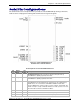
Serial Pin Configurations
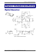
The serial interface use an 16-pin interface to provide an on-board DAA with tip and ring connections,
audio circuit for call-progress monitoring and serial interface via logic level signals.
Figure 2–2. Serial SocketModems Pins
Available with or without LED Pins
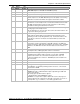
Pin Descriptions for Serial SocketModem Devices
Pin
#
Signal
Name
I/O
Type
Description
1 Tip I/O
Tip Signal from Telco. Tip connection to the phone line (RJ11 Pin 3).
SocketModem is Tip/Ring is polarity insensitive.
2 Ring I/O
Ring Signal from Telco. Ring connection to the phone line (RJ11 Pin 4).
SocketModem is Tip/Ring is polarity insensitive.
24 –RESET I
Modem Reset (with weak pull-up). The active low –RESET input resets the
SocketModem logic and returns the AT command set to the original factory
default values or to "stored values" in NVRAM. –RESET is tied to VCC
through a 400ms time constant circuit for "Power-on-Reset" functionality. The
modem is ready to accept commands within 6.5 seconds of power-on or reset.
Reset must be asserted for a minimum of 300 ns.
26 DGND
Ground
29 DCDIND
DCD LED. Output from 74AC05 with 1500 Ohms pull-up.
30 RXIND
RX LED. Output from 74AC05 with 1500 Ohms pull-up.