® MultiModem ZBA MT9234ZBA-Series MT9234ZBA MT9234ZBA-V User Guide
MultiModem ZBA MT9234ZBA-Series User Guide MT9234ZBA, MT9234ZBA-V PN S000387A, Version A Copyright This publication may not be reproduced, in whole or in part, without prior expressed written permission from MultiTech Systems, Inc. All rights reserved. Copyright © 2007, by Multi-Tech Systems, Inc. Multi-Tech Systems, Inc. makes no representations or warranty with respect to the contents hereof and specifically disclaims any implied warranties of merchantability or fitness for any particular purpose.
Table of Contents Table of Contents CHAPTER 1 – INTRODUCTION................................................................................................................................ 5 Features.........................................................................................................................................................5 AT Commands Info........................................................................................................................................
Table of Contents Fax Branding Statement..............................................................................................................................30 Canadian Limitations Notice........................................................................................................................30 Industry Canada ..........................................................................................................................................
Chapter 1 – Introduction Chapter 1 – Introduction Congratulations on your purchase of the MultiModem ZBA modem. You have acquired one of the finest intelligent voice/data/fax modems available today from one of the world’s oldest modem manufacturers: Multi-Tech Systems, Inc. The MT9234ZBA-Series is available in global and non-global builds with and without the voice feature. The MT9234ZBA global product is approved in 40+ countries.
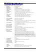
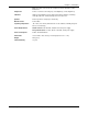
Chapter 1 – Introduction Technical Specifications The MT9234ZBA-Series modem meets the following specifications: 6 Trade Name ® MultiModem ZBA Model Number MT9234ZBA Build Number MT9234ZBA, MT9234ZBA-V Server-to-Client Data Rates 56K speeds when accessing a V.90 or V.92 server (actual speed depends on server capabilities and line conditions) Client-to-Server Data Rates Up to 48Kbps when accessing a V.
Chapter 1 – Introduction Note: Any cables connected to the computer should be shielded to reduce interference. Diagnostics Power-on self test, local analog loop, local digital loop, remote digital loop. Indicators LEDs for Transmit Data, Receive Data, Carrier Detect, 56K bps, 33.6K bps, 14.4K bps, Off Hook, Terminal Ready, Error Correction, Fax. Speaker Internal speaker for call progress monitoring.
Chapter 3 – Operation Chapter 2 – Installation This chapter shows you step-by-step how to set up your Multi-Tech MT9234ZBA modem. Safety Warnings • • • • • • • • Use this product only with UL- and CUL-listed computers (U.S.A. and Canada) To reduce the risk of fire, use only 26 AWG (.41mm) or larger telephone wiring. Never install telephone wiring during a lightning storm. Never install a telephone jack in a wet location unless the jack is specifically designed for wet locations.
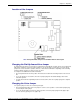
Chapter 3 – Operation Location of the Jumpers Note: The Speaker Mode Jumper is for the Modem with the Voice Option Changing the Dial-Up/Leased-Line Jumper As shipped from the factory, your modem is configured for normal dial-up operation. That is, the modem must dial a phone number to connect to another modem. To use the modem on a leased line, you must change jumper J2 to select leased line operation, and J3 to select whether it will be the originating or the answering modem.
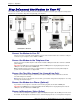
Chapter 3 – Operation Step 2: Connect the Modem to Your PC Turn off your computer. Place the modem in a convenient location, and then connect it to your computer’s serial port, the telephone line or leased line, AC power, and, optionally, your telephone. Connections - No Voice Connections With Voice Connect the Modem to Your PC Plug one end of the serial cable into the RS232 connector on the modem and the other end into a serial port connector on your computer, such as COM1 or COM2.
Chapter 3 – Operation Connect Speakers (Voice Option) For speakerphone or voice mail applications, use a 1/8-inch plug male-to-male stereo patch cord to connect the SPKR jack on the side of the modem to the LINE IN jack on your sound card. If your sound card does not have a LINE IN jack, use its MIC jack. The stereo male-to-male patch cord can be purchased at a local PC retail store. If you do not have a sound card, you can plug an unamplified speaker directly into the SPKR jack.
Chapter 3 – Operation 4. 5. 6. 7. 8. The Global Wizard dialog box appeared. Click Next. The Global Wizard searches for your modem and identifies it. Click Next. Select the country/region in which the modem will be used. Click Next. Review your country/region choice. If it is correct, click Next to configure the modem. When Global Wizard announces that the parameters have been set, click Finish to exit. Using AT Commands to Configure Your Modem Non-Windows users can configure the modem using AT commands.
Chapter 3 – Operation Chapter 3 – Operation About the Front Panel The LED indicators on the front panel indicate status, configuration, and activity: TD – Transmit Data. Flashes when the modem is transmitting data to another modem. RD – Receive Data. Flashes when the modem is receiving data. CD – Carrier Detect. Lights when the modem detects a valid carrier signal from another modem. It is on when the modem is communicating with the other modem, and off when the link is broken.
Chapter 3 – Operation Connecting to the Internet Your Multi-Tech modem is your gateway to the Internet and the World Wide Web. To access the Internet and Web via your modem, you must establish a dial-up account with an Internet service provider (ISP). To locate an ISP near you, look in a local directory or computer publication.
Chapter 4 – Remote Configuration Chapter 4–Remote Configuration Remote configuration is a network management tool that allows you to configure MT9234ZBA modems anywhere in your network from one location. With password-protected remote configuration, you can issue AT commands to a remote modem for maintenance or troubleshooting as if you were on site. Basic Procedure The following steps can be used when the connection is established by the local or the remote modem.
Chapter 5 – Callback Security Chapter 5 – Callback Security This chapter describes how to use callback security with your modem. Callback security protects your network from unauthorized access and helps control long-distance costs. When callback security is enabled, all callers are requested to enter a password. If a valid password is received, the modem hangs up and returns the call by dialing a phone number that is stored with the password.
Chapter 5 – Callback Security Setting Callback Security Message Parity The modem’s password prompt and messages parity must match the parity of the computer to which the modem is connected. 1. Open a data communications program such as HyperTerminal. 2. In the terminal window, type AT#Sxxxxxxxx, where xxxxxxxx is your password. Press ENTER. The modem responds with OK if the setup password is correct and ERROR if it is wrong. 3. The modem’s parity default value is No parity (AT#CBP0).
Chapter 5 – Callback Security 5. 6. 7. 8. After the delay specified by the #CBDn command, the callback modem calls the number associated with the password. If the callback modem is unable to establish a connection, it tries again, up to the number of attempts specified by the #CBAn command. After the modems reconnect, the following message reappears: Password> Type the same password that you used to initiate the call.
Chapter 5 – Callback Security Direct Connection Use this procedure when you want to connect without first being called back. The password that you use must be set up for an optional direct connection. 1. Using a data communications program such as HyperTerminal, dial the number of the callback modem. 2. When the connection is established, the callback modem responds with the following message: Password> 3. Type a direct connection password, press the - key, and then press ENTER.
Chapter 5 – Callback Security Callback Assignments Form Location Password Telephone Number 0 1 2 3 4 5 6 7 8 9 10 11 12 13 14 15 16 17 18 19 20 21 22 23 34 25 26 27 28 29 20 Multi-Tech Systems, Inc.
Chapter 6– Troubleshooting Chapter 6 – Troubleshooting Your modem was thoroughly tested at the factory before it was shipped. If you are unable to make a successful connection, or if you experience data loss or garbled characters during your connection, it is possible that the modem is defective. However, it is more likely that the source of your problem lies elsewhere. The following symptoms are typical of problems you might encounter: • • • • • • • • • • None of the LEDs light when the modem is on.
Chapter 6 – Troubleshooting • If the modem is on, the cable is plugged into the correct port, the communication software is configured correctly, and you still don’t get an OK, the fault might be in the serial cable. Make sure it is firmly connected at both ends. • Is this the first time you have used the cable? If so, it may not be wired correctly. Check the cable description on the packaging to make sure the cable is the right one for your computer.
Chapter 6– Troubleshooting The Modem Disconnects While Online • If you are not using Modem on Hold, Call Waiting can interrupt your connection when someone tries to call you. If you have Call Waiting service, disable it before each call. In most telephone areas in North America, you can disable Call Waiting by preceding the telephone number with *70 (but first check with your local telephone company). You can automatically disable Call Waiting by including the disabling code in the modem’s dial prefix (e.
Chapter 6 – Troubleshooting Data Is Being Lost • If you are using data compression and a high speed serial port, set the serial port baud rate to two to six times the data rate. • • Make sure the flow control method you selected in software matches the method selected in the modem.
Chapter 7– Warranty, Service, & Technical Support Chapter 7 – Warranty, Service, and Technical Support Multi-Tech Warranty Statement Multi-Tech Systems, Inc., (hereafter “MTS”) warrants that its products will be free from defects in material or workmanship for a period of two, five, or ten years (depending on model) from date of purchase, or if proof of purchase is not provided, two, five, or ten years (depending on model) from date of shipment.
Chapter 7 – Warranty,Service, & Technical Support number. If the product is out of warranty, a payment in advance is required. Accptable means of payment include credit card, wire transfer or a check in U.S. dollars drawn on a U.S. bank. Repaired units shall be shipped freight collect, unless other arrangements are made in advance. Please direct your questions regarding technical matters, product configuration, verification that the product is defective, etc.
Appendix A – Upgrading the Modem’s Firmware Appendix A – Upgrading the Modem’s Firmware Your modem is controlled by semi-permanent software, called firmware, which is stored in flash memory. Firmware is nonvolatile; that is, it remains stored in memory when the modem is turned off. However, it can be changed by either the manufacturer or the user as bugs are fixed or new features are added.
Appendix A – Upgrading Your Modem’s Firmware Step 4: Extract the Upgrade Files 1. Install the Flash Wizard utility by double-clicking the file name in Windows Explorer. 2. Extract the upgrade files by double-clicking the file name. The extracted files include a .HEX file, which contains the upgrade data, and a Readme file. 3. Copy the upgrade .HEX file into the Flash Wizard folder, which, in a default installation, is at C:\Program Files\MultiTech Systems\Flash Wizard\.
Appendix B – Regulatory Compliance Appendix B – Regulatory Compliance FCC Part 15 Regulation This equipment has been tested and found to comply with the limits for a Class B digital device, pursuant to Part 15 of the FCC rules. These limits are designed to provide reasonable protection against harmful interference in a residential installation.
Appendix B – Regulatory Compliance Fax Branding Statement The Telephone Consumer Protection Act of 1991 makes it unlawful for any person to use a computer or other electronic device, including fax machines, to send any message unless such message clearly contains the following information: • Date and time the message is sent • Identification of the business or other entity, or other individual sending the message • Telephone number of the sending machine or such business, other entity, or individual This
Appendix B – Regulatory Compliance International Modem Restrictions Some dialing and answering defaults and restrictions may vary for international modems. Changing settings may cause a modem to become non-compliant with national telecom requirements in specific countries. Also note that some software packages may have features or lack restrictions that may cause the modem to become non-compliant. New Zealand Telecom Warning Notice 1.
Appendix B – Regulatory Compliance Appendix C – Waste Electrical and Electronic Equipment WEEE (Waste Electrical and Electronic Equipment) Statement July, 2005 The WEEE directive places an obligation on EU-based manufacturers, distributors, retailers, and importers to take-back electronics products at the end of their useful life.
Appendix D – Installing a Modem under Linux Appendix D – Installing a Modem under Linux This appendix explains how to install a modem on a computer operating under the Red Hat Linux 6.2 operating system. Other versions of Red Hat and other Linux operating systems should be similar. Briefly, in Linux, you do not need drivers for most standard external modems and most internal ISA bus modems. Programs in Linux commonly call upon the port, rather than the modem.
Appendix E – Connecting to a Cisco Router Appendix E – Connecting to a Cisco Router Connecting to a Cisco Router Console Port ® The console port on the Cisco IOS router is an asynchronous serial port configured as data communications equipment (DCE). For Cisco 1000, 1600, 2500, 2600, and 3600 series routers, the console port uses an RJ-45 connector. WARNING: Do not connect the modem to the Cisco router’s auxiliary port. This procedure and document apply only to the Cisco router’s console port.
Appendix E – Connecting to a Cisco Router Step 3: Console Port Final Setup Send the following command string to the modem connected to the console port of the Cisco router: AT%R1&W0 The %R1 command sets E0, Q1, &D0, &K0, $SB9600, and %S1, and the &W0 command stores the commands to memory. The %R1 command sets the following functions: E0 Turns command echo off Q1 Turns result codes off &D0 Ignores DTR from the DTE &K0 Selects no flow control $SB9600 Sets the serial baud rate to 9600 bps.
Appendix E – Connecting to a Cisco Router Appendix F – C-ROHS HT/TS Substance Concentration 依照中国标准的有毒有害物质信息 根据中华人民共和国信息产业部 (MII) 制定的电子信息产品 (EIP) 标准-中华人民共和国《电子信息产品污染控制管理办法》(第 39 号),也称作中国 RoHS,下表列出了 Multi-Tech Systems Inc.
Index Index A G AT commands &D ...................................................................................13 &F....................................................................................13 &W ............................................................................13, 16 O .....................................................................................16 AT Commands.......................................................................5 Autoanswer ................................
Index S Safety .....................................................................................8 Serial Cable..........................................................................22 Serial Port ............................................................................13 South African Statement ......................................................32 Specifications, Technical .......................................................6 Speed Sserial Port...............................................