LAN-to-LAN Routing for Central-Site and Branch Office Networks Model MTASR1-100 User Guide
User Guide 88302550 Revision A RouteFinder (Model MTASR1-100) This publication may not be reproduced, in whole or in part, without prior expressed written permission from Multi-Tech Systems, Inc. All rights reserved. Copyright © 1998, by Multi-Tech Systems, Inc. Multi-Tech Systems, Inc. makes no representations or warranties with respect to the contents hereof and specifically disclaims any implied warranties of merchantability or fitness for any particular purpose. Furthermore, Multi-Tech Systems, Inc.
Contents Chapter 1 - Introduction and Description Introduction ....................................................................................................................................................... 6 Preview of this Guide .................................................................................................................................. 6 Related Documentation ......................................................................................................................
Chapter 6 - Service, Warranty and Tech Support Introduction ..................................................................................................................................................... 50 Limited Warranty ............................................................................................................................................. 50 On-line Warranty Registration ...........................................................................................................
Chapter 1 - Introduction and Description
RouteFinder MTASR1-100 User Guide Introduction Welcome to Multi-Tech's new RouteFinder™, model number MTASR1-100, an IP/IPX router for interconnecting LANs using switched or dedicated wide area telecommunicaitons links. The MTASR1100 provides IP and IPX routing and Media Access Control (MAC) layer bridging for all other protocols over its WAN port. It features a 10Base-T or AUI port for local LAN connection, Command Port for configuration, and an RS-232/V.
Chapter 1 - Introduction and Description Chapter 5 - Remote Configuration and Management Chapter 5 provides procedures for changing the configuration of a remote RouteFinder, located elsewhere on a LAN or at the other end of a modem connection. This chapter also describes typical Telnet client and Web-browser management of the RouteFinder.
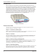
RouteFinder MTASR1-100 User Guide Front Panel The front panel contains three groups of LEDs that provide the status of the LAN connection, WAN Link activity, and general status of the RouteFinder. The Ethernet LEDs display the activity of the LAN whether the RouteFinder is connected to the LAN, transmitting or receiving packets, and if a collision is in progress. The WAN Link LEDs display the status of the link (i.e.
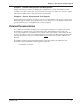
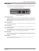
Chapter 1 - Introduction and Description Back Panel The cable connections for the RouteFinder are made at the back panel. Three groups of cables are used on the RouteFinder, the Command Port, WAN link, and the Ethernet. The cable connections are shown in Figure 1-3 and defined in the following groups. RS232/V.35 10BASE T COMMAND PORT ON OFF 10BASE 2 POWER Figure 1-3. Back Panel RS-232/V.35 Connector The RS-232/V.35 connector is used to connect the RouteFinder to a WAN device.
RouteFinder MTASR1-100 User Guide Shunts A shunt on the WAN port allows the same connector to be configured for an ITU-T V.35 electrical interface signaling or EIA-232C/D signaling. The ITU-T V.35 signaling levels are generally more reliable for high speed data and/or longer cable distances. The EIA-232C/D signaling is intended for data rates of 19.2 Kbps or less and cable lengths of 50 feet or less. For higher speeds and/or longer distances, the V.35 is generally preferred.
Chapter 1 - Introduction and Description Specifications The RouteFinder conforms to the following specifications. • Routing Protocols - IP and IPX and bridging for all others • Ethernet LAN Interface - 10Base-T (twisted pair) or 10Base2 (ThinNet) BNC • WAN Interface - 1 async or sync link (RS-232C/V.35) • Command Port - 19.2 Kbps Asynchronous • Two 4-megabyte DRAMs (1 meg by 36 bytes at 70 nanosecond SIMMs) Caution: SIMM speed and size cannot be mixed.
RouteFinder MTASR1-100 User Guide 12 MTASR1-100
Chapter 2 - Installation
RouteFinder MTASR1-100 User Guide Unpacking The shipping box contains the RouteFinder, external power supply, command port adapter cable (short cable with RJ-45 on one end and DB25 on the other), your Quick Start Guide, and three disks (i.e., the RouteFinder User Guide, and the RouteFinder Software). Inspect the contents for signs of any shipping damage. If damage is observed, do not power up the unit; contact Multi-Tech’s Technical Support for advice (refer to Chapter 6).
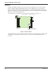
Chapter 2 - Installation Changing Shunt Position The WAN port shunt must be moved to the V.35 position whenever you want to connect the RouteFinder to an external composite link device with a V.35 interface. Do the following. 1. Ensure that the external power supply is disconnected from the RouteFinder. 2. Turn the RouteFinder upside down and remove the cabinet mounting screw at the center back of the cabinet.
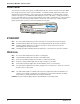
RouteFinder MTASR1-100 User Guide Cabling your RouteFinder Cabling your RouteFinder involves making the proper WAN, Ethernet, Command Port and power connections. Figure 2-4 shows the back panel connectors and the associated cable connections. To connect the cables to your RouteFinder, do the following. 1. If the WAN link needs to be changed to a V.35 interface, perform the “Changing Shunt Position” procedure. RS232/V.
Chapter 3 - Software Loading and Configuration
RouteFinder MTASR1-100 User Guide Introduction The following loading procedure does not provide every screen or option in the process of installing the RouteFinder software. It is assumed that a technical person with a thorough knowledge of Windows and the software loading process is doing the installation. Loading your Software 1. Run Windows on the PC that is connected to the RouteFinder’s Command Port. 2. Insert the RouteFinder 3.
Chapter 3 - Software Loading and Configuration 8. The Port Setup dialog box selects the COM port of the PC that is connected to the Command Port of the RouteFinder. On the Select Port window, click the down arrow and choose the COM port of your PC (COM1 -- COM4) that is connected to the RouteFinder. 9. Click OK to continue. The Setup Complete dialog box is displayed. Click Finish to continue. 10. The “Do you want to perform upgrade?” dialog box is displayed. Click No to skip the upgrade process. 11.
RouteFinder MTASR1-100 User Guide Note: Clicking No prevents the defaults from being downloaded to the RouteFinder. You are returned to the program manager, and in Windows 95/NT you will see an open window with shortcut icons for all the various utility programs provided in the RouteFinder software. 12. The “Router is Running. Reboot to download setup?” dialog is displayed. Click Yes. 13. The Novell IPX Protocol Default Setup dialog box is displayed.
Chapter 3 - Software Loading and Configuration When you manually assign network numbers, make sure they match the network numbers assigned to your local file server (if any). 17. WAN: Enter the WAN Network number for the WAN port by clicking the Network Number box and back-spacing through the default number entering your new WAN number. The WAN network number must be the same as at the RouteFinder on the other end of a LAN-to-LAN link.
RouteFinder MTASR1-100 User Guide If the WAN port is being set up to answer a call, click the Answering option(the Dial Number field becomes inactive). 27. Click OK when you are satisfied with your selections. 28. The Checking Router dialog box is displayed. Click OK. 29. The Writing Setup dialog box (with the current date and the file size in bytes) is displayed as the software sends the configuration file to the RouteFinder. Next, the Rebooting dialog box is displayed. 30.
Chapter 3 - Software Loading and Configuration Setting Up Your Remote User Database The remote user database supports remote dial-in users for user name, password, and port availability. Each dial-in user needs an entry in this database. You can add remote users, remove users, or edit information in the database. 1. Win3.1 users - From the Program Manager, click the Remote User Data Base icon.
RouteFinder MTASR1-100 User Guide 4. Build your user database by filling in the following fields for each user. User Name. The User Name can have as many as 39 characters. All printable characters are permitted with the restriction that no blanks are allowed in the user name. In dial-in and dial-out applications, the user name is treated as a case insensitive string. User Password. The User Password can have as many as 7 characters.
Chapter 4 - RouteFinder Software
RouteFinder MTASR1-100 User Guide Introduction This chapter describes the RouteFinder’s software from an applications standpoint, showing how to make changes in the configuration with recommendations on the impact of any changes. The major configuration parameters were set when the software was loaded into your PC and the setup configuration was downloaded to the RouteFinder at the conclusion of the software installation. The RouteFinder software is designed for the Microsoft ® Windows ® environment.
Chapter 4 - RouteFinder Software Download Firmware This utility enables you to download the firmware to the RouteFinder. This may be necessary in the case of repair or upgrade. To download the firmware, choose Download Firmware from the RouteFinder program group, and the Open dialog box is displayed (if the RouteFinder is running, you will be queried to reboot to update firmware; click OK to proceed and the Open dialog will be displayed).
RouteFinder MTASR1-100 User Guide Router Configuration The Router Setup menu has 13 buttons (two rows of five buttons plus one row with three buttons) that enable you to display and change the protocol stacks, define the output of the RouteFinder, perform network management functions, test the communications link, print messages received from the target RouteFinder, and download setup information to the RouteFinder.
Chapter 4 - RouteFinder Software An IP address is a combination of a network number and a host number or ID. IP address masks are used to specify the network or subnet portion of the IP address. IP addresses and masks are 32-bit values. These are usually provided in what is known as the dotted decimal notation. The net mask specifies the network or subnet portion of an IP address. The net mask is a 32-bit value presented in a dotted decimal notation.
RouteFinder MTASR1-100 User Guide The Advanced tab controls the timers, Dynamic Host Configuration Protocol (DHCP) and Domain Name System (DNS) options, the default route, filters, and Static Routes. In most cases, you should not have to change any of the timers (i.e., default TTL, reassembly timeout, RIP response time and RIP route aging time). The DNS Resolver is supplied for remote Telnet clients when the router is configured for remote access and the terminal server application is enabled.
Chapter 4 - RouteFinder Software Open Shortest Path First (OSPF) Open Shortest Path First (OSPF) is a common TCP/IP routing protocol that provides robust and efficient routing support in the most demanding Internet environments. OSPF calculates routes using the number of routers, the transmission speed, expected delays, and the cost of the route. Version 2 of the OSPF protocol is designed to be run internal to a single Autonomous System.
RouteFinder MTASR1-100 User Guide IPX Setup The IPX Virtual Port Setup dialog box controls the four frame types, and the WAN port setup. The Advanced tab enables IPX routing, auto learn of Ethernet network numbers, and the distributed name of the RouteFinder. The RIP and SAP default timers should not have to be changed for most applications. Disabling IPX and SPX Watchdog Spoofing in the Bandwidth Optimization group has proven effective under certain circumstances with Citrix clients.
Chapter 4 - RouteFinder Software The Advanced tab contains options which control the routing of the protocol and auto learn of Ethernet network numbers, defines the broadcast name of the RouteFinder, and IPX filtering. If bridging of IPX packets is desired, IPX routing must be disabled and frame type support for the frame type must be enabled. If there is a server on the local segment, then IPX network number auto learn should be enabled.
RouteFinder MTASR1-100 User Guide Spanning Tree Setup When Bridging is enabled, the Spanning Tree Setup dialog box controls simple transparent bridging between two remote Ethernet LANs. However, if your internetwork contains any loops or redundant links, then the Spanning Tree Algorithm must also be enabled. If you use only the IP and IPX protocols, leave bridging disabled to allow the RouteFinder to operate more efficiently. The RouteFinder defaults with one logical WAN port mapped to a DLCI.
Chapter 4 - RouteFinder Software WAN Port Setup The WAN Port Setup dialog box controls how the port is configured (i.e., frame relay or point-topoint). If the WAN port is configured for frame relay, then the mode of the port is synchronous. If the port is configured for point-to-point, then the mode can be either synchronous or asynchronous. If the mode is asynchronous, then the connection method can be either Answering or Dialing.
RouteFinder MTASR1-100 User Guide Point-to-Point Setup The PPP Port Setup dialog box controls the WAN port protocol, dial on demand, and remote port setup. The WAN port protocol can be either Point-to-Point Protocol (PPP) or Serial Line Internet Protocol (SLIP). Of these two protocols, PPP is the more robust as it allows the end-points to negotiate the use of the link and protocol parameters in a standardized way and also allows for standardized encapsulation of the packets.
Chapter 4 - RouteFinder Software Frame Relay Setup The Frame Relay dialog box displays the Management Type, details of that management type, and the number of DLCIs that are active. Frame relay parameters have to be set up exactly as they are provisioned from the network service. Therefore, it is important not to change any frame relay parameters; and, when adding new DLCIs that they agree with the way your frame relay service is provisioned.
RouteFinder MTASR1-100 User Guide Frame Relay DLCI The Frame Relay DLCI dialog box initially displays a default DLCI that is mapped to a default IP address, STP WAN Number, a CIR setting of 56K, a Be of zero, and the mode set to Adhere to CIR. Before you add new DLCIs, you have to add logical WANs to the IP port. To add a new DLCI Number, enter the number in the DLCI window. You do not have to enter the leading zeros. When you click the Add button, the new DLCI appears in the Configured DLCI’s window.
Chapter 4 - RouteFinder Software Applications Setup This dialog box lets you set up support for Telnet, TFTP (Trivial File Transfer Protocol), WEB, and Asynchronous Gateway servers in the RouteFinder. This dialog box is displayed by clicking Others on the Router Setup dialog box. Telnet is an applications level protocol commonly found in IP-based networks that allow terminal emulation at a remote workstation.
RouteFinder MTASR1-100 User Guide Scripting To enable scripting, click WAN from the Router Setup menu. The Wan Port Setup dialog box is displayed. Click the Script Enable check box to enable scripting on this WAN port. Click the Script button to access the scripting options. The Script Dialog menu is displayed. From this menu you can edit, compile, and download scripts. For more information on scripting, click the Help button or refer to Appendix B - Scripting.
Chapter 5 - Remote Configuration and Management
RouteFinder MTASR1-100 User Guide Introduction This chapter provides procedures for changing the configuration of a remote RouteFinder. Remote configuration allows a PC at one site (local site) to dial a remote RouteFinder and change the configuration of that remote unit. Remote configuration can be accomplished either directly through the LAN or remotely using modems.
Chapter 5 - Remote Configuration and Management If your Modem Initialization String, Initialization Response, or Connect Response values are different from the defaults in the dialog box, refer to your modem user documentation and change the default values to match your modem. Click on OK when you are satisfied with all your selections. 6. You are returned to the Windows program. Start the RouteFinder Configuration program. Windows 3.
RouteFinder MTASR1-100 User Guide LAN-Based Remote Configuration Windows Sockets Compliant TCP/IP Stack The configuration program requires a Windows Sockets compliant TCP/IP stack. Microsoft provides a TCP/IP stack free for Windows for Workgroups 3.11 and Windows 95/NT. TCP/IP protocol software must be installed and functional before the configuration program can be used. 1. You must assign an Internet (IP) address for the PC and for each node that will be managed by the configuration program.
Chapter 5 - Remote Configuration and Management 6. The RouteFinder Setup dialog box is then displayed. This is the dialog box for the remote RouteFinder. You can select any of the available buttons and change the configuration (or setup) and download the changes to the remote RouteFinder. Refer to Chapter 4 for a description of the RouteFinder software. For definitions of each dialog box or fields within a dialog box, refer to the on-line helps provided in the software. 7.
RouteFinder MTASR1-100 User Guide Remote Management This section describes typical client applications that can be used to configure the RouteFinder remotely. It is important to note that although any subsequent changes to configuration can be made using these applications, the initial setup and configuration of the RouteFinder must be done on the local PC, using the RouteFinder software provided with your unit.
Chapter 5 - Remote Configuration and Management Router Management The Router Management Menu provides five functional options in addition to the option of escaping and closing the Telnet session. Dial-Out The Dial-out option (Option 1) on the Router Management Menu enables a Telnet user to configure the WAN port for a dial-out session. The default configuration of 115200 bps, 8N1 can be used for the dial-out session, or the user can specify each parameter for the port (e.g.
RouteFinder MTASR1-100 User Guide WEB Browser Management The RouteFinder can be accessed from anywhere on the connected Internet through its built-in WEB Browser interface. To enable this function, you must check this option in Other setup. Depending on the rights of the user (read/write, or read only), it is possible to view the current parameters and statistics of the RouteFinder as well as configure and download setup changes to the unit.
Chapter 6 - Service, Warranty and Tech Support
RouteFinder MTASR1-100 User Guide Introduction This chapter starts out with statements about your RouteFinder two-year warranty. The next section, Tech Support, should be read carefully if you have questions or problems with your RouteFinder. It includes the technical support phone numbers, space for recording your product information, and an explanation of how to send in your RouteFinder should you require service.
Chapter 6 - Service, Warranty and Tech Support Tech Support Multi-Tech Systems has an excellent staff of technical support personnel available to help you get the most out of your Multi-Tech product. If you have any questions about the operation of this unit, call 1800-972-2439. Please fill out the RouteFinder information (below), and have it available when you call.
RouteFinder MTASR1-100 User Guide Service If your tech support specialist decides that service is required, your RouteFinder may be sent (freight prepaid) to our factory. Return shipping charges will be paid by Multi-Tech Systems. Include the following information with your RouteFinder: • a description of the problem. • return billing and return shipping addresses. • contact name and phone number. • check or purchase order number for payment if the RouteFinder is out of warranty.
Chapter 6 - Service, Warranty and Tech Support The Multi-Tech BBS For customers who do not have Internet access, Multi-Tech Systems maintains a bulletin board system (BBS) that mirrors its FTP site. Information available from the BBS includes new product information, product upgrade files, and problem-solving tips. The phone number for the Multi-Tech BBS is (800) 392-2432 (USA and Canada) or (612) 785-3702 (international and local).
RouteFinder MTASR1-100 User Guide 7. If you select Zmodem, the file will transfer automatically. If you select another protocol, you may have to initiate the transfer yourself. (In most data communications programs, the PAGE DOWN key initiates the download.) 8. When the download is complete, press ENTER to return to the File Menu. 9. To exit the BBS, type G and press ENTER.
Appendixes
RouteFinder MTASR1-100 User Guide Appendix A - Cabling Diagrams Command Port Cable PIN NO. To COMMAND PORT Connector PIN NO. 1 1 2 2 TRANSMIT DATA (BA) 3 3 RECEIVE DATA (BB) 4 4 5 5 6 6 7 7 8 8 SIGNAL GROUND (AB) To DTE Device (Terminal Device i.e.
Appendixes WAN Cables 13 12 25 24 11 10 23 9 22 8 7 21 20 6 19 5 18 4 17 3 16 2 15 1 14 RS232C/V.24 * Link Cable PIN NO. To External Synchronous Modem/DSU Connector PIN NO. 1 1 2 2 3 3 4 4 5 5 7 7 8 8 15 15 17 17 20 20 25 25 CHASSIS GROUND (AA) TRANSMIT DATA (BA) To MultiRouter Link 1,2 or 3 RS232C/V.
RouteFinder MTASR1-100 User Guide Appendix B - Script Language The script file can be used to automate certain operations. The script file is a text file containing a sequence of commands. The structure of a script file is succinctly expressed by the following grammar.
Appendixes the argument name in the formal parameter list by the keyword VAR; otherwise, the argument is passed by value. Only variables can be passed by address. Expressions like A+B, where A and B are integer variables can be passed by value but cannot be passed by address. Two basic types of variables are supported: INTEGER and STRING In the STRING, since the ASCII null character is internally used to indicate the end of the sequence, it cannot be part of the string.
RouteFinder MTASR1-100 User Guide Example Script: proc main; string login_prompt; string user_name; string password_prompt; string password; string shell_menu; string shell_menu_response; integer timeout; timeout=10; login_prompt=”login:”; user_name=”user1”; password_prompt=”Password:”; password=”user1”; shell_menu=”choice:”; shell_menu_response=”1”; transmit(“A”); wait(1) transmit(“T^M”); waitfor (“OK”,10); transmit (“A”); wait (1); transmit (“T”); wait (1); transmit (“DT963^M”); if (waitfor (login_prompt
Appendixes Appendix C - Regulatory Information Class A Statement FCC Part 15 This equipment has been tested and found to comply with the limits for a Class A digital device, pursuant to Part 15 of the FCC Rules. These limits are designed to provide reasonable protection against harmful interference when the equipment is operated in a commercial environment.
RouteFinder MTASR1-100 User Guide Appendix D - TCP/IP TCP/IP TCP/IP (Transmission Control Protocol/Internet Protocol) is a protocol suite and related applications developed for the U.S. Department of Defense in the 1970s and 1980s specifically to permit different types of computers to communicate and exchange information with one another. TCP/IP is currently mandated as an official U.S. Department of Defense protocol and is also widely used in the UNIX community.
Appendixes UDP, described in RFC 768 (ftp://ds.internic.net/rfc/rfc768.txt) provides an end-to-end datagram (connectionless) service. Some applications, such as those that involve a simple query and response, are better suited to the datagram service of UDP because there is no time lost to virtual circuit establishment and termination. UDP’s primary function is to add a port number to the IP address to provide a socket for the application.
RouteFinder MTASR1-100 User Guide Internet Protocol (IP) IP is the Internet standard protocol that tracks Internetwork node addresses, routes outgoing messages and recognizes incoming messages, allowing a message to cross multiple networks on the way to its final destination. The IPv6 Control Protocol (IPV6CP) is responsible for configuring, enabling, and disabling the IPv6 protocol modules on both ends of the point-to-point link.
Glossary of Terms
RouteFinder MTASR1-100 User Guide A Access: The T1 line element made up of two pairs of wire that the phone company brings to the customer premises. The Access portion ends with a connection at the local telco (LEC or RBOC). Accunet Spectrum of Digital Services (ASDS): The AT&T 56K bps leased (private) line service. Similar to services of MCI and Sprint. ASDS is available in nx56/64K bps, where n=1, 2, 4, 6, 8, 12.
Glossary Basic Rate Interface (BRI): An ISDN access interface type comprised of two B-channels each at 64K bps and one Dchannel at 64K bps (2B+D). Bell Operating Companies (BOC): The family of corporations created during the divestiture of AT&T. BOCs are independent companies which service a specific region of the US. Also called Regional Bell Operating Companies (RBOCs).
RouteFinder MTASR1-100 User Guide Channel: A data communications path between two computer devices. Can refer to a physical medium (e.g., UTP or coax), or to a specific carrier frequency. Channel Bank: A device that acts as a converter, taking the digital signal from the T1 line into a phone system and converting it to the analog signals used by the phone system. A channel bank acts as a multiplexer, placing many slowspeed voice or data transactions on a single high-speed link.
Glossary inter-LATA basis by AT&T and on an intra-LATA basis by the BOCs. Data Service Unit (DSU): A device that provides a digital data service interface directly to the data terminal equipment. The DSU provides loop equalization, remote and local testing capabilities, and a standard EIA/CCITT interface. Dedicated Line: A communication line that is not switched. The term leased line is more common.
RouteFinder MTASR1-100 User Guide Ethernet: A 10-megabit baseband local area network that allows multiple stations to access the transmission medium at will without prior coordination, avoids contention by using carrier sense and deference, and resolves contention by using collision detection and transmission. Ethernet uses carrier sense multiple access with collision detection (CSMA/CD).
Glossary developing and deploying frame relay equipment. Frame Relay Implementors Forum: A group of companies supporting a common specification for frame relay connection to link customer premises equipment to telco network equipment. Their specification supports ANSI frame relay specs and defines extensions such as local management.
RouteFinder MTASR1-100 User Guide and data over a digital communications line. ISDN is a world-wide telecommunications service that uses digital transmission and switching technology to support voice and digital data communications. Frame relay was partially based on ISDN’s data link layer protocol (LAPD). Frame relay can be used to transmit across ISDN services offering circuit-switched connection at 64K bps and higher speeds. Contrast Public Switched Telephone Network (PSTN).
Glossary M Management Information Base (MIB): A database of network management information used by the Common Management Information Protocol (CMIP) and the Simple Network Management Protocol (SNMP). Megacom: An AT&T service with a normal WATS line (typically T1) between the customer premise and the AT&T serving class 4 CO are the customer’s responibility. MegaLink: BellSouth’s leased T1 service. Message: Associated with such terms as packet, frame, and segment. 1.
RouteFinder MTASR1-100 User Guide Out of Frame (OOF): A T1 alarm condition that is logged on the loss of 2, 3 or 4 of 5 consecutive FT framing bits. P Packet: 1. In data communication, a sequence of binary digits, including data and control signals, that is transmitted and switched as a composite whole. The data, control signals and, possibly, error control information are arranged in a specific format. 2. Synonymous with data frame. 3.
Glossary Q Quantizing: The process of analog-to-digital conversion by assigning a range, from the contiguous analog values, to a discrete number. R Random Access Memory (RAM): A computer’s primary workspace. All data must be stored in RAM (even for a short while), before software can use the processor to manipulate the data. Before a PC can do anything useful it must move programs from disk to RAM. When you turn it off, all information in RAM is lost.
RouteFinder MTASR1-100 User Guide Simple Network Management Protocol (SNMP): TCP/IP protocol that allows network management. Simultaneous Voice Data (SVD): A technology for letting a user send data via a modem, and use a handset to talk to another user at the same time over the same connection. The alternative, making a second call, can be expensive or even impossible. The uses for SVD are telecommuting, videoconferencing, distant learning, tech support, etc.
Glossary Transmission Control Protocol / Internet Program (TCP/IP): A multi-layer set of protocols developed by the US Department of Defense to link dissimilar computers across dissimilar and unreliable LANs. Terminal: The screen and keyboard device used in a mainframe environment for interactive data entry. Terminals have no “box”, which is to say they have no file storage or processing capabilities. Terminal Adapter (TA): An ISDN DTE device for connecting a non-ISDN terminal device to the ISDN network.
RouteFinder MTASR1-100 User Guide W Wide Area Network (WAN): 1. A network that provides communication services to a geographic area larger than that served by a local area network or a metropolitan area network, and that may use or provide public communication facilities. 2. A data communications network designed to serve an area of hundreds or thousands of miles; for example, public and private packet-switching networks, and national telephone networks. Contrast with local area network (LAN).
Index Index Symbols 10Base 2 Connector ............................................... 9 10Base T Connector ............................................... 9 A ASCII String .......................................................... 20 Authentication ....................................................... 29 B Bridging Enable ..................................................... 34 C Cable Connections .................................................. 9 Cables LAN Cables .................................
RouteFinder MTASR1-100 User Guide IPX Setup .......................................................... 32 Spanning Tree Setup ......................................... 34 WAN Port Setup ................................................ 35 SNAP .................................................................... 20 Software Uninstall ............................................................. 27 Spanning Tree Bridging Setup Bridging Enable .................................................