® MultiVOIP GSM SIP-to-Cellular Gateways Model: MVPGSM-2 User Guide
User Guide S000450A Wireless MultiVOIP GSM Unit (Model: MVPGSM-2) This publication may not be reproduced, in whole or in part, without prior expressed written permission from Multi-Tech Systems, Inc. All rights reserved. Copyright © 2008, by Multi-Tech Systems, Inc. Multi-Tech Systems, Inc. makes no representations or warranty with respect to the contents hereof and specifically disclaims any implied warranties of merchantability or fitness for any particular purpose. Furthermore, Multi-Tech Systems, Inc.
CONTENTS CHAPTER 1 – DESCRIPTION AND SPECIFICATIONS ..................................................................................................... 4 Introduction .......................................................................................................................................................... 4 Specifications ........................................................................................................................................................
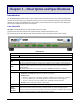
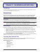
Chapter 1 – Description and Specifications Introduction The MultiVOIP GSM provides wireless voice communications over the Internet or an Intranet. By integrating wireless connectivity into your existing data network, you can realize substantial savings on inter-office long distance toll charges. The MVPGSM has “phone books,” which are directories set up to simulate dialing and connecting as though the call was in the local area. Front Panel LEDs LED Types.
Chapter 1: Description & Specifications Computer Requirements The computer on which the MVPGSM configuration program is installed must meet these requirements: • • must be IBM-compatible PC with MS Windows operating system; must have an available COM port for connection to the MultiVOIP GSM. However, this PC does not need to be connected to the MultiVOIP GSM permanently. It only needs to be connected when local configuration and monitoring are done.
Chapter 1: Description & Specifications PTCRB Requirements Note There cannot be any alteration to the authorized antenna system. The antenna system must be the same type with similar in-band and out-of-ban radiation patterns and maintain the same specifications. FCC Requirements Note The antenna gain, including cable loss, must not exceed 3.0 dBi at 1900 MHz / 1.6 dBi at 850 MHz for mobile operating configurations and 7.0 dBi at 1900 MHz / 2.3 dBi at 850 MHz for fixed mounted operations, as defined in 2.
Chapter 2 – Installation and Activation Introduction The MultiVOIP GSM is equally usable as tabletop unit or mounted in a location with good reception. The initial setup is best performed before any mounting is done. Safety Warnings Lithium Battery Caution A lithium battery on the voice/fax channel board provides backup power for the timekeeping capability. The battery has an estimated life expectancy of ten years. When the battery starts to weaken, the date and time may be incorrect.
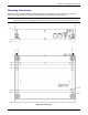
Chapter 2: Installation & Activation Mounting Instructions When not used as a tabletop device, the bottom panel of the MVPGSM has six keyed slots for versatility of mounting. The dimensions (in inches) provided below allow for placement nearly anywhere. Caution: Please make sure your signal strength is adequate for the planned site of mounting before actually finalizing placement. Verifying signal strength procedures can be found in the Setup Overview section.
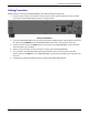
Chapter 2: Installation & Activation Cabling Procedure Cabling involves connecting the MultiVOIP GSM to your LAN and telephone equipment. 1. Connect a power cord to the transformer and to a live AC outlet, and then attach the barrel connector to the back of the MultiVOIP GSM as shown in the figure below. Cabling for MVPGSM-2 2. Connect the MultiVOIP GSM to a PC by using a RJ-45 (male) to DB-9 (female) cable.
Chapter 2: Installation & Activation GSM Instructions Step 1 – Activate Your Wireless Account Select a wireless network provider and follow their directions to activate your account and receive your SIM cards. Phone Numbers Every channel will have its own unique phone number. The phone number may simply be given to you by your wireless service provider or it may be on the SIM card or both. Wireless provider implementations may vary.
Chapter 3 – Software Installation Introduction Configuring software for your MultiVOIP GSM entails three tasks: Loading the software onto the PC (this is “Software Installation” and is discussed in this chapter). Setting values for telephony and IP parameters that will fit your system (details are in Chapter 4). Establishing “phonebooks” that contain the various dialing patterns for VOIP calls made to different locations (a detailed discussion of this is found in Chapter 5).
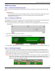
Chapter 3: Software Installation Installation wizard screen Press Enter or click Next to continue. 4. Follow the on-screen instructions to install your MultiVOIP GSM software. The first screen asks you to choose the destination for the MultiVOIP GSM software. Destination screen Choose a location and click Next. 5. At the next screen, you must select a program folder location for the MultiVOIP GSM software program icon. Click Next. Transient progress screens will appear while files are being copied.
Chapter 3: Software Installation 6. On the next screen you can select the COM port that the command PC will use when communicating with the MultiVOIP GSM unit. After software installation, the COM port can be re-set in the MultiVOIP GSM Software (from the sidebar menu, select Connection | Settings to access the COM Port Setup screen or use keyboard shortcut Ctrl + G).
Chapter 3: Software Installation Setup Overview With the software now installed, you are ready to get your MultiVOIP GSM set up and working. There are a few necessary settings that need to be entered in the configuration software to achieve this and they are noted in the action lists for the categories below. The following chapters will cover all aspects in detail, but here we will cover the basic configuration needed to start VOIP communications.
Chapter 3: Software Installation Ethernet/IP A unique LAN IP address is required for the MultiVOIP GSM unit as well as a subnet mask and Gateway IP for minimal functionality. Other settings in this category pertain to specific features and protocols that can be used, but are not necessary for basic operation. Details for all settings are provided in chapter 4. IP settings Actions: • Select Packet Prioritization if used o Set 802.
Chapter 3: Software Installation Voice The individual channels must be set up before use. The Copy Channel button can save a lot of time during this step if channels are to be set with the same parameters. Some options should be noted for future changes if necessary, but the defaults are likely to work without adjustment. Voice settings Multi-Tech Systems, Inc.
Chapter 3: Software Installation Actions: • Select Channel o Choose channel parameters: Fax and modem parameters are not available at this time Modem Relay Enable allows modem traffic through the VOIP system Adjusting the Voice Gain and DTMF should not be done as it may adversely affect voice and DTMF quality Select a Coder or allow Automatic negotiation Advanced Features • Silence Compression, when enabled, will not send IP packets during times of silence • Echo Cancellation removes echo to impro
Chapter 3: Software Installation Wireless Interface The Wireless Interface Parameters are the settings for the GSM connection. The Copy Channel button can save a lot of time during this step if channels are to be set with the same parameters. Wireless Interface Parameters Multi-Tech Systems, Inc.
Chapter 3: Software Installation Actions: • Select Channel o Channel 1 or 2 • Disable Interface o Check box: Enable or Disable Interface • Use Module for DTMF and Tone Generation o Check box: Enable or Disable DTMF and Tone generation (this is used in conjunction with out of band DTMF) • Enable Caller ID o Check box: Enable or Disable Caller ID (this is for Caller ID information coming in from the wireless network) • No Response Timer o Internal timer for command response time.
Chapter 3: Software Installation Call Signaling The MultiVOIP GSM utilizes the SIP protocol for communication with other VOIP units. Additional details for all settings are found in Chapter 4.
Chapter 3: Software Installation Regional Select the country or region that the MultiVOIP GSM unit will operate in, or use the custom option if the available settings are not adequate. Regional Parameters Actions: • Select the choice that matches the location of the MultiVOIP GSM from the Country/Region field o If there is not a selection to fit your needs, you may select Custom and set the tones manually Multi-Tech Systems, Inc.
Chapter 3: Software Installation Phone Book Without a populated phone book, the VOIP unit is unable to translate call traffic. You will need the information for both a local and any remote sites that are to be used. Detailed descriptions and examples are available in chapter 5. To better understand the meaning behind ‘Inbound’ and ‘Outbound’ please see the graphic below. Inbound and Outbound directions Phone Book screens Multi-Tech Systems, Inc.
Chapter 3: Software Installation Actions: • Select Outbound Phone Book o Select Add Entry o Accept Any Number: may be selected to allow any phone number from the wireless network to initiate a SIP call to the IP address of the SIP end point listed below o Destination Pattern: When a call from the wireless network is received, the subsequent digits received from the wireless side are used to match the destination pattern and route the call to the SIP end point with the IP address listed below o Remove Prefix
Chapter 4 – Configuring Your MultiVOIP GSM Introduction There are two methods of configuring your MultiVOIP GSM; one is through a web interface, and the other is through the Windows software interface. There are several necessary parameters that must be set for the MultiVOIP GSM unit to operate properly, with some additional settings that are optional. You must know the IP address that will be used, the IP mask, the Gateway IP, and the Domain Name Server information.
Chapter 4: Configuring your MVPGSM How to Navigate Through the Software The MultiVOIP GSM software is launched from the Start button and is found in the All Programs area under the title of MultiVOIP GSM x.xx (where x represents version number). The top option is “Configuration” – choose this.
Chapter 4: Configuring your MVPGSM Ethernet/IP This section covers the Ethernet settings needed for the MultiVOIP GSM unit. In each field, enter the values that fit the network to which the MultiVOIP GSM will be connected to. For many of the settings, the default values will work best – try these settings first unless you know you definitely need to change a parameter. Network parameters The Ethernet/IP Parameters fields are described in the tables and text passages below. Multi-Tech Systems, Inc.
Chapter 4: Configuring your MVPGSM Ethernet/IP Parameter Definitions Field Name Values Description Ethernet Parameters Packet Prioritization Y/N Select to activate prioritization under 802.1p protocol (described below). (802.1p) Frame Type Type II, SNAP Must be set to match network’s frame type. Default is Type II. 802.1p A draft standard of the IEEE about data traffic prioritization on Ethernet networks. The 802.1p draft is an extension of the 802.1D bridging standard. 802.
Chapter 4: Configuring your MVPGSM Ethernet/IP Parameter Definitions (continued) Field Name Diff Serv Parameter fields Values Description Diff Serv PHB (Per Hop Behavior) values pertain to a differential prioritizing system for IP packets as handled by Diff Serv-compatible routers. There are 64 values, each with an elaborate technical description.
Chapter 4: Configuring your MVPGSM Voice/Fax Setting the Voice Parameters. The Voice/Fax section needs to be set for each channel to be used. However, once you have established a set of Voice parameters for a particular channel, you can apply this entire set of Voice parameters to another channel by using the Copy Channel button and its dialog box. To copy a set of Voice parameters to all channels, select “Copy to All” and click Copy.
Chapter 4: Configuring your MVPGSM Voice/Fax Parameter Definitions Field Name Default Values -- Select Channel Copy Channel Voice Gain Input Gain 1-2 --+31dB to –31dB +31dB to –31dB -- Output Gain DTMF Gain DTMF Gain, High Tones +3dB to -31dB & “mute” DTMF Gain, Low +3dB to Tones -31dB & “mute” DTMF Parameters Duration (DTMF) 60 – 3000 ms DTMF Out of In/Out of Band Band, or Inband Out of Band RFC 2833, Mode SIP Info Description When this button is clicked, all Voice/FAX parameters are set to their def
Chapter 4: Configuring your MVPGSM Voice/Fax Parameter Definitions (continued) Coder Parameters Manual or Automatic Coder Selected Coder G.711 a/u law 64 kbps; G.726, @ 16/24/32/40 kbps; G.727, @ nine bps rates; G.723.1 @ 5.3 kbps, 6.3 kbps; G.729, 8kbps; Net Coder @ 6.4, 7.2, 8, 8.8, 9.6 kbps Selected Coder additional choices G.711, G.729 -orG.729, G.711 Max bandwidth (coder) 11 – 128 kbps Determines whether selection of coder is manual or automatic.
Chapter 4: Configuring your MVPGSM Voice/Fax Parameter Definitions (continued) Field Name Values Description AutoCall/Offhook Alert Parameters Auto Call / Offhook Alert AutoCall, The AutoCall option enables the local MultiVOIP GSM to call a remote SIP endpoint without the user having to dial a Phone Directory Database number. As soon as you access the local MultiVOIP GSM voice/fax channel, the MultiVOIP GSM immediately connects to the SIP end point identified in the Phone Number box of this option.
Chapter 4: Configuring your MVPGSM Configurable Payload Type The Configurable Payload Type is located on the bottom of the Voice/Fax screen. The Configurable Payload Type is used when the remote side uses a different payload type for the associated features. Wireless Interface The Wireless Interface parameters are set individually for each channel. In each field, enter the values that fit your particular setup.
Chapter 4: Configuring your MVPGSM Wireless Interface parameter definitions Field Name Select Channel Disable Interface Use Module for DTMF Generation Values 1–2 Check box Check box Enable Caller ID No Response Timer Minimum Signal Quality Required SIM Pincode SIM PIN Description Select which channel you want to set parameters for. Enable or Disable the interface. Enable or Disable DTMF generation. When checked, the wireless module will generate DTMF tones to the cell network.
Chapter 4: Configuring your MVPGSM Call Signaling The MultiVOIP GSM uses SIP call signaling. SIP Session Initiation Protocol is the only option available for application layer control of the MultiVOIP GSM. The fields are detailed in the table below. SIP call signaling Multi-Tech Systems, Inc.
Chapter 4: Configuring your MVPGSM SIP Call Signaling Parameter Definitions Field Name Values Description SIP Parameters Signaling Port port Port number on which the MultiVOIP GSM UserAgent software module will be waiting for any incoming SIP requests. Default = 5060 Use SIP Proxy Y/N Allows the MultiVOIP GSM to work in conjunction with a proxy server. Allow Incoming Calls Through SIP Proxy Only Y/N When selected, incoming calls are accepted only if those calls come through the proxy.
Chapter 4: Configuring your MVPGSM Regional The Regional Parameters are used to set the phone signaling tones and cadences. For the country selected, the standard set of frequency pairs will be listed for dial tone, busy tone, ‘unobtainable’ tone (fast busy or trunk busy), ring tone, and other, more specialized tones. If you need settings that are not available, the Custom selection will let you set the tones to what is necessary. The Regional Parameters fields are described in the table below.
Chapter 4: Configuring your MVPGSM “Regional Parameter” Definitions Field Name Country/Region Values USA, Japan, UK, Custom Advisory screen Description Name of a country or region that uses a certain set of tone pairs for dial tone, ring tone, busy tone, unobtainable tone (fast busy tone), survivability tone (tone heard briefly, 2 seconds, after going off hook denoting survivable mode of VOIP unit), re-order tone (a tone pattern indicating the need for the user to hang up the phone), and intercept tone (
Chapter 4: Configuring your MVPGSM Setting Custom Tones and Cadences (optional). The Regional Parameters dialog box has a secondary dialog box that allows you to customize DTMF tone pairs to create unique ring-tones, dial-tones, busy-tones or “unobtainable” tones or “re-order” tones or “survivability” tones for your system. This screen allows the user to specify tone-pair attributes that are not found in any of the standard national/regional telephony toning schemes.
Chapter 4: Configuring your MVPGSM SMTP Setting the SMTP Parameters (Log Reports by Email). The SMTP Parameters screen is applicable when the VOIP administrator has chosen to receive log reports by email (this is done by selecting the “SMTP” checkbox in the Others screen and selecting “Enable SMTP” in the SMTP Parameters screen.) Email Address for VOIP (for email call log reporting) This is needed only if log reports of VOIP call traffic are to be sent by email.
Chapter 4: Configuring your MVPGSM “SMTP Parameters” Definitions Field Name Enable SMTP Values Y/N Requires Authentication Y/N Login Name Password Mail Server IP Address Port Number Mail Type Subject alpha-numeric alpha-numeric n.n.n.n 25 text or html text Reply-To Address email address Recipient Address email address Mail Criteria Number of Records integer Number of Days integer Multi-Tech Systems, Inc. Description In order to send log reports by email, this box must be checked.
Chapter 4: Configuring your MVPGSM The SMTP Parameters dialog box has a secondary dialog box, accessed by the Select Fields button, that allows you to customize email logging. The MultiVOIP GSM software logs data about many aspects of the call traffic going through the MultiVOIP GSM. The Custom Fields screen lets you pick which aspects will be included in the email log reports. “Custom Fields” Definitions Field Description Field Description Select All Log report to include all fields shown.
Chapter 4: Configuring your MVPGSM RADIUS In general, RADIUS is concerned with authentication, authorization, and accounting. The MultiVOIP GSM supports the accounting and authentication functions. The accounting function is well suited for billing of VOIP telephony services. In the Select Attributes secondary screen (accessed by clicking on Select Attributes button), the VOIP administrator can select the parameters to be tallied by the RADIUS server. RADIUS settings Multi-Tech Systems, Inc.
Chapter 4: Configuring your MVPGSM The fields of the RADIUS screen are described in the table below. RADIUS Screen Field Definitions Field Name Enable Accounting Values Y/N Description When checked, the MultiVOIP GSM will access the accounting functionality of the RADIUS server. Server Address n.n.n.n IP address of the RADIUS server that handles accounting (billing) for the current MultiVOIP GSM unit.
Chapter 4: Configuring your MVPGSM Logs/Traces The Logs/Traces screen lets you choose how the VOIP administrator will receive log reports about the MultiVOIP GSM’s performance and the phone call traffic that is passing through it. Log reports can be received in one of two ways: • in the MultiVOIP GSM program (interface), or • via email (SMTP) Logs and Filters screens Multi-Tech Systems, Inc.
Chapter 4: Configuring your MVPGSM If you enable console messages, you can customize the types of messages to be included/excluded in log reports by clicking on the Filters button and using the Console Messages Filter Settings screen. If you use the logging function, select the logging option that applies to your VOIP system design. If you intend to use a SysLog Server program for logging, click in that Enable check box. The common SysLog logical port number is 514.
Chapter 4: Configuring your MVPGSM NAT Traversal Setting the NAT (Network Address Translation) Traversal parameters. STUN (Simple Traversal of UDP through NATs) is a protocol for assisting devices behind a NAT firewall or router with their packet routing. NAT Traversal Descriptions for NAT Traversal screen fields are presented in the table below. NAT Traversal Definitions Field Name Enable (STUN) Values Y/N Description Enables STUN client functionality in the MultiVOIP GSM.
Chapter 4: Configuring your MVPGSM Supplementary Services Supplementary Services features derive from the H.450 standard, - even though the H.450 standard refers only to H.323, Supplementary Services are still applicable to the SIP VOIP protocols. Of the features implemented under Supplementary Services, three are very closely related: Call Transfer, Call Hold, and Call Waiting. Call Transfer. Call Transfer allows one party to re-connect the party with whom they have been speaking to a third party.
Chapter 4: Configuring your MVPGSM Supplementary Services Parameter Definitions Field Name Select Channel Values 1-2 Description The channel to be configured is selected here. Call Transfer Enable Y/N Select to enable the Call Transfer function in the VOIP unit. This is a “blind” transfer and the sequence of events is as follows: Callers A and B are having a conversation. Caller A wants to put B into contact with C. Caller A dials call transfer sequence.
Chapter 4: Configuring your MVPGSM Save Settings Save & Reboot Saving the MultiVOIP GSM Configuration. When values have been set for all of the various operating parameters, click on Save Setup in the sidebar, then Save & Reboot. Creating a User Default Configuration. When a “Setup” (complete grouping of parameters) is being saved, you will be prompted about designating that setup as a “User Default” setup.
Chapter 4: Configuring your MVPGSM Troubleshooting Software Issues In the lower left corner of the screen, the connection status of the MultiVOIP GSM will be displayed. The messages in the lower left corner will change as detection occurs. The message “MultiVOIP GSM Found” confirms that the MultiVOIP GSM is in contact with the MultiVOIP GSM configuration program. If the message displayed is “MultiVOIP GSM Not Found!” please try the resolutions below.
Chapter 5 – Phone Book Configuration Introduction The wireless connectivity of the MVPGSM provides the cost-savings of wireless-to-wireless connections and inexpensive long distance to an existing location. By flagging calls that would connect to a remote site with another MultiVOIP unit or calls that are to be long distance, the MVP GSM can save money by routing those calls through the wireless connection instead of the standard PSTN.
Chapter 5: Phonebook Configuration Sample Configurations ¾ ¾ ¾ ¾ MVPGSM-to-MVPGSM MVPGSM as a Stand Alone Unit Analog VOIP and MVPGSM Load Balancing General Notes Suppose you want to call a phone number outside of your building using a phone station that is an extension from your PBX system (if present). What digits must you dial? Often a “9” must be dialed to “get an outside line” through the PBX (i.e., to connect to the PSTN).
Chapter 5: Phonebook Configuration Example 3: Your company has an IP PBX system with an analog VOIP unit for local calls and direct calls to the office in another city and an MVPGSM that will handle all long distance calls. With this setup, a call control module handles the call routing – when an extension requests an outside line (by dialing a “9” first, for example) the call control module then watches what the first digit after the 9 is.
Chapter 5: Phonebook Configuration Example Outbound Phone Books The Outbound Phone Book is the director of where calls will be routed – whether that is to a specific phone number (Any Number) or to the IP address of a remote VOIP unit for resending as a local call or out to the wireless network to take advantage of wireless plan savings. Below you will find the Outbound Phone Book settings for the examples that were detailed in the sample Phone Book Configurations above.
Chapter 5: Phonebook Configuration Phone Book Descriptions Outbound Phone Book/List Entries Fields in the “Details” section that are grayed out are not used by the SIP protocol. Outbound Phone Book Multi-Tech Systems, Inc.
Chapter 5: Phonebook Configuration Add/Edit Outbound Phone Book Add/Edit screen Enter Outbound Phone Book data for your MultiVOIP GSM unit. Note that the Advanced button gives access to the Alternate IP Routing feature, if needed. Alternate IP Routing can be implemented in a secondary screen (as described after the primary screen field definitions below). The fields of the Add/Edit Outbound Phone Book screen are described in the table below. Multi-Tech Systems, Inc.
Chapter 5: Phonebook Configuration Add/Edit Outbound Phone Book: Field Definitions Field Name Accept Any Number Values Y/N Description When checked, “Any Number” appears as the value in the Destination Pattern field. The Any Number feature works differently depending on whether or not an external routing device is used (Proxy for SIP protocol). When no external routing device is used.
Chapter 5: Phonebook Configuration Clicking on the Advanced button brings up the Alternate Routing secondary screen. This feature provides an alternate path for calls if the primary IP network cannot or does not respond within the timeframe of the Round Trip Delay. Often in cases of failure, call traffic is temporarily diverted into the PSTN. However, this feature could also be used to divert traffic to a redundant (backup) unit in case one SIP end point fails.
Chapter 5: Phonebook Configuration Inbound Phone Book/List Entries The “Details” and “Registration Options” sections will display information based on the setup and protocols chosen. Inbound phonebook entries Multi-Tech Systems, Inc.
Chapter 5: Phonebook Configuration Add/Edit Inbound Phone Book Add/Edit Inbound Phone Book Multi-Tech Systems, Inc.
Chapter 5: Phonebook Configuration Enter Inbound Phone Book data for your MultiVOIP GSM. The fields of the Add/Edit Inbound Phone Book screen are described in the table below. Add/Edit Inbound Phone Book: Field Definitions Field Name Values Description Accept Any Number Y/N When checked, “Any Number” appears as the value in the Remove Prefix field. The Any Number feature of the Inbound Phone Book does not work when an external routing device is used (Proxy for SIP protocol).
Chapter 5: Phonebook Configuration Authorized User Name and Password for SIP To enable the Registration Options on the Add/Edit Inbound Phone Book, you have to activate Use SIP Proxy Option on the Call Signaling, SIP Parameters Screen. Then add the IP address for the Primary Proxy in the SIP Proxy Parameters. This allows you to add a Username and Password to the Inbound Phone Book entry.
Chapter 6 – Using the Software Introduction This chapter will primarily cover the day to day operation and maintenance sections of the MultiVOIP GSM software. How to update the firmware and software are also covered here should either be needed. This section will mainly focus on the Statistics section of the configuration software, but there are references to a few of the other sections as they are used more in the daily operations than in a setup situation.
Chapter 6: Using the Software System Information screen This screen presents system information at a glance. It is found under the Configuration section and its primary use is in troubleshooting. The information presented in the figure below is for reference only and is not meant to be an exact match of your system. System information screen System Information Parameter Definitions Field Name Boot Version Values nn.
Chapter 6: Using the Software Statistics Section Ongoing operation of the MVPGSM, whether it is in a MVPGSM/PBX setting or MVPGSM/telco-office setting, can be monitored for performance using the Statistics functions of the MVPGSM software. The following screens are examples of what can be shown and are followed by detailed descriptions of the categories involved. The model and signaling used will affect what is available for display. Call Progress Call progress screen Multi-Tech Systems, Inc.
Chapter 6: Using the Software Call Progress Details: Field Definitions Field Name Channel Values 1-n Call Details Duration H/M/S Mode Voice or FAX Voice Coder G.723, G.729, G.711, etc. IP Call Type SIP IP Call Direction incoming, outgoing Packet Details Packets Sent integer value Packets Rcvd integer value Bytes Sent integer value Bytes Rcvd integer value Packets Lost integer value From – To Details Gateway Name alphanumeric (from) string IP Address (from) n.n.n.
Chapter 6: Using the Software Call Progress Details: Field Definitions (continued) Field Name Values Supplementary Services Status Call on Hold alphanumeric Call Waiting alphanumeric Caller ID “Calling Party + identifier”; “Alerting Party + identifier”; “Busy Party + identifier”; “Connected Party + identifier” Call Status fields Call Status hangup, active Wireless Module ready, Status registering SIM Registration “registered Status to…”, not registered Signal Strength 0-99 Note section (Options & Signa
Chapter 6: Using the Software Logs Log statistics screen The table below describes the fields of the Logs screen. Multi-Tech Systems, Inc.
Chapter 6: Using the Software Logs Screen Details: Field Definitions Field Name Log # column Values 1 or higher dd:mm:yyyy hh:mm:ss hh:mm:ss SIP success or failure Incoming, outgoing Mode column voice or FAX From column gateway name To column gateway name Special Buttons Start Date, Time column Duration column Type Status column IP Direction Previous Next First Last Delete File -----Call Details Voice coder Coder protocol Disconnect Reason "Normal" or "Local" DTMF Capability inband, out of band Outboun
Chapter 6: Using the Software IP Statistics IP statistics screen UDP versus TCP. (User Datagram Protocol versus Transmission Control Protocol). UDP provides unguaranteed, connectionless transmission of data across an IP network. By contrast, TCP provides reliable, connectionoriented transmission of data. Both TCP and UDP split data into packets called “datagrams.
Chapter 6: Using the Software IP Statistics: Field Definitions Field Name IP Address Values n.n.n.n “Clear” button -Total Packets Transmitted integer value Received integer value Received with integer Errors value UDP Packets Description IP address of the MultiVOIP GSM. For an IP address to be displayed here, the MultiVOIP GSM must have DHCP enabled. Its IP address, in such a case, is assigned by the DHCP server. Clears packet tallies from memory. Sum of packets of all types.
Chapter 6: Using the Software Link Management The Link Management screen is essentially an automated utility for pinging endpoints on your VOIP network. This utility generates pings of variable sizes at variable intervals and records the response to the pings. Link management Link Management screen Field Definitions Field Name Values Monitor Link fields IP Address to Ping n.n.n.
Chapter 6: Using the Software Servers SIP Proxies This window lists all the SIP proxy servers configured and the active server with which the system is registered. SIP proxies SIP Proxies (Statistics, Servers): Field Definitions Field Name Values Column Headings IP Address n.n.n.n Port port Type Status Primary, Alternate registered, not registered Multi-Tech Systems, Inc. Description The IP address of the SIP proxy by which the MultiVOIP GSM is governed.
Chapter 6: Using the Software Advanced Packetization Time You can use the Packetization Time screen to specify definite packetization rates for coders selected in the Voice/FAX Parameters screen (in the “Coder Options” group of fields). The Packetization Time screen is accessible under the “Advanced” options entry in the sidebar list of the main VOIP software screen. In dealing with RTP parameters, the Packetization Time screen is closely related to both Voice/FAX Parameters and to IP Statistics.
Chapter 6: Using the Software MultiVOIP GSM Program Menu Items After the MultiVOIP GSM program is installed on the PC, it can be launched from the Programs group of the Windows Start menu ( Start | Programs | MultiVOIP GSM x.xx | … ). In this section, we describe the software functions available on this menu. Several basic software functions are accessible from the MultiVOIP GSM software menu, as shown below.
Chapter 6: Using the Software Setting and Downloading User Defaults The Download User Defaults command allows you to maintain a known working configuration that is specific to your VOIP system. You can then experiment with alterations or improvements to the configurations confident that a working configuration can be restored if necessary. 1.
Chapter 6: Using the Software Setting a Password Windows Interface After a user name has been designated and a password has been set, that password is required to gain access to any functionality of the MultiVOIP GSM software. Only one user name and password can be assigned to a VOIP unit. The user name will be required when communicating with the MultiVOIP GSM via the web browser interface. NOTE: Record your user name and password in a safe place.
Chapter 6: Using the Software Password verification When the MVPGSM program asks for the password at launch of program, if CANCEL is selected, the program will simply shut down. The MVPGSM program will produce an error message if an invalid password is entered. Invalid password Web Browser Interface Setting a password is optional when using the MultiVOIP GSM web browser interface.
Chapter 6: Using the Software Upgrading Software As noted earlier, the Upgrade Software command transfers from the controller PC to the MultiVOIP GSM unit. The settings can be either Factory Default Settings or Current Configuration Settings. Upgrade software path Multi-Tech Systems, Inc.
Chapter 6: Using the Software FTP Server File Transfers (“Downloads”) Multi-Tech has built an FTP server into the MultiVOIP GSM unit. Therefore, file transfers from the controller PC to the VOIP unit can be done using an FTP client program or even using a browser (e.g., Internet Explorer, Netscape, or Firefox, used in conjunction with Windows Explorer). The terminology of “downloads” and “uploads” gets a bit confusing in this context.
Chapter 6: Using the Software 3. Install FTP Client Program or Use Substitute. You should install an FTP client program on the controller PC. FTP file transfers can be done using a web browser (e.g., Firefox or Internet Explorer) in conjunction with a local Windows browser a (e.g., Windows Explorer), but this approach is somewhat clumsy (it requires use of two application programs rather than one) and it limits downloading to only one VOIP unit at a time.
Chapter 6: Using the Software 6. Contact MultiVOIP GSM FTP Server. You must make contact with the FTP Server in the VOIP using either a web browser or FTP client program. Enter the IP address of the MultiVOIP GSM’s FTP Server. If you are using a browser, the address must be preceded by “ftp://” (otherwise you’ll reach the web interface within the MultiVOIP GSM unit). FTP address 7. Log In. Use the User Name and password established in item #2 above.
Chapter 6: Using the Software Download with FTP Client Program: • In the local directory browser of the FTP client program, locate the directory holding the MultiVOIP GSM program files. The default location will be C:\Program Files \Multi-Tech Systems \MultiVOIP GSM xxxx yyyy (where x and y represent MultiVOIP GSM model numbers and software version numbers). • In the FTP client program window, drag-and-drop files from the local browser pane to the pane for the MultiVOIP GSM FTP server.
Chapter 6: Using the Software Web Browser Interface Web interface main page You can control the MultiVOIP GSM unit with a graphic user interface (interface) based on the common web browser platform. Qualifying browsers are Internet Explorer 6+, Netscape 6+, and Mozilla Firefox 1.0+. MultiVOIP GSM Web Browser Interface Overview Function Configuration Prerequisite Browser Version Requirement Java Requirement Remote configuration and control of MultiVOIP GSM units.
Chapter 6: Using the Software The Windows interface gives access to commands via icons and pull-down menus whereas the web interface does not. The web interface, however, cannot perform logging in the same direct mode done in the Windows interface. However, when the web interface is used, logging can be done by email (SMTP). The graphic layout of the web interface is also somewhat larger-scale than that of the Windows interface. For that reason, it’s helpful to use as large of a video monitor as possible.
Chapter 6: Using the Software Browser choice When installation is complete, the Java program runs automatically in the background as a plug-in supporting the MultiVOIP GSM web interface. No user actions are required. After the Java program has been installed, you can access the MultiVOIP GSM using the web browser interface. Close the MultiVOIP GSM Windows interface. Start the web browser. Enter the IP address of the MultiVOIP GSM unit. Enter a password when prompted.
Chapter 6: Using the Software SysLog Server Functions Multi-Tech has built SysLog server functionality into the software of the MultiVOIP GSM units. SysLog is a de facto standard for logging events in network communication systems. The SysLog Server resides in the MultiVOIP GSM unit itself. To implement this functionality, you will need a SysLog client program (sometimes referred to as a “daemon”).
Appendix A – Cable Pin-outs & Ports Command Cable RJ-45 Connector End-to-End Pin Info 1 2 3 4 5 6 7 8 RJ-45 connector plugs into Command Port of MultiVOIP GSM. DB-9 connector plugs into serial port of command PC (which runs MultiVOIP GSM configuration software). Ethernet Connector The functions of the individual conductors of the MultiVOIP GSM’s Ethernet port are shown on a pin-by-pin basis below.
Appendix B – Regulatory Information EMC, Safety, and R&TTE Directive Compliance The CE mark is affixed to this product to confirm compliance with the following European Community Directives: Council Directive 2004/108/EC of 31 December, 2004 on the approximation of the laws of Member States relating to electromagnetic compatibility, and Council Directive 2006/95/EC 12 December, 2006 on the harmonization of the laws of Member States relating to electrical equipment designed for use within certain voltage lim
Appendix C: Regulatory Information Industry Canada This Class A digital apparatus meets all requirements of the Canadian Interference-Causing Equipment Regulations. Cet appareil numérique de la classe A respecte toutes les exigences du Reglement Canadien sur le matériel brouilleur. Canadian Limitations Notice Notice: The Industry Canada label identifies certified equipment. This certification means that the equipment meets certain telecommunications network protective, operational and safety requirements.
Appendix C – Waste Electrical and Electronic Equipment (WEEE) Statement July, 2005 The WEEE directive places an obligation on EU-based manufacturers, distributors, retailers and importers to take-back electronics products at the end of their useful life. A sister Directive, ROHS (Restriction of Hazardous Substances) complements the WEEE Directive by banning the presence of specific hazardous substances in the products at the design phase.
Appendix D – C-ROHS HT/TS Substance Concentration 依照中国标准的有毒有害物质信息 根据中华人民共和国信息产业部 (MII) 制定的电子信息产品 (EIP) 标准-中华人民共和国《电子信息产品污染控制管理办法》(第 39 号),也称作中国 RoHS,下表列出了 Multi-Tech Systems Inc.
INDEX Auto Disconnect ....................................................................... 32 AutoCall/Offhook ..................................................................... 32 Cabling ....................................................................................... 9 Call Hold .................................................................................. 48 Call Progress fields ................................................................... 67 Call Transfer .........................