Standalone Voice/IP Gateway Model MVP 800 Proprietary Mode User Guide
User Guide S0000216 Revision A MultiVOIP 800 (Model MVP 800) This publication may not be reproduced, in whole or in part, without prior expressed written permission from MultiTech Systems, Inc. All rights reserved. Copyright © 2001, by Multi-Tech Systems, Inc. Multi-Tech Systems, Inc. makes no representations or warranties with respect to the contents hereof and specifically disclaims any implied warranties of merchantability or fitness for any particular purpose. Furthermore, Multi-Tech Systems, Inc.
Contents Chapter 1 - Introduction and Description Introduction ................................................................................................................................................ 6 Preview of this Guide ................................................................................................................................. 6 MultiVOIP Application ..............................................................................................................................
Viewing Call Progress .............................................................................................................................. Viewing Logs ............................................................................................................................................ Viewing Log Entry Details .................................................................................................................. Viewing Channel Totals .............................................
Chapter 1 - Introduction and Description
Chapter 1 - Introduction and Description Introduction Welcome to Multi-Tech's new standalone Voice/IP Gateway which allows analog voice and fax communication over an IP network. Multi-Tech’s new voice/fax over IP gateway technology allows voice and fax communication to ride, with no additional expense, over your existing IP network, which has traditionally been data-only.
Chapter 1 - Introduction and Description Chapter 5 - Remote Configuration and Management Chapter 5 provides procedures for changing the configuration of a remote MultiVOIP. Remote configuration allows you to change the configuration of a unit by simply connecting two modems between the two MultiVOIPs and remotely controlling the unit. Chapter 5 also describes typical client applications such as Telnet and Web-based management, which are used for remote configuration of the MultiVOIP.
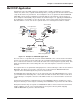
Chapter 1 - Introduction and Description MultiVOIP Application A typical Voice Over IP (VOIP) network is shown in Figure 1-2 with a headquarters site and three remote sites (Sales office, regional and marketing offices). This typical Voice Over IP network can be set up via the Internet or your Intranet.
Chapter 1 - Introduction and Description Phone Directory Data Base Number Description 101 Headquarters Trunk Ext 4 102 Headquarters Trunk Ext 5 103 Headquarters Trunk Ext 6 104 Headquarters Trunk Ext 7 201 Sales KTS 201 202 Sales PSTN 202 301 Regional 301 302 Regional 302 401 Marketing Trunk Ext 9 402 Marketing Trunk Ext 10 Channel 1 IP Address 201.23.122.118 2 201.23.122.118 3 201.23.122.118 4 201.23.122.118 1 205.24.123.119 2 205.24.123.119 1 206.25.124.120 2 206.25.124.120 1 207.26.
Chapter 1 - Introduction and Description Using the same example as above, but calling the Regional office. A person at headquarters would pick up a telephone and dial say trunk extension 5. This connects channel 2 of the headquarters MultiVOIP. A second dial tone is heard, then you would dial, for example, 301. The telephone connected to channel 1 of the Regional office MultiVOIP rings and your voice conservation takes place.
Chapter 1 - Introduction and Description Front Panel Description The front panel contains three groups of LEDs that provide the status of the Ethernet connection, Voice/Fax channels, and general status of the MultiVOIP. The front panel is shown in Figure 1-3, and a description of each LED follows. Figure 1-3. Front Panel ETHERNET RCV Receive Data indicator blinks when packets are being received from the local area network.
Chapter 1 - Introduction and Description Back Panel Description The cable connections for the MultiVOIP are made at the back panel. Connectors include Power, Command Port (RS232), Ethernet (10BASE-T), Voice/Fax Channels (E&M, FXO and FXS). The cable connectors are shown in Figure 1-4 and defined in the following groups.
Chapter 1 - Introduction and Description Specifications • Two 1 Meg by 32 byte at 70 nanosecond SIMM is 8 Mb DRAM Caution: SIMM speed and size cannot be mixed • Two Meg of flash memory Ethernet Port • Single Ethernet Interface - 10BASE-T (twisted pair) keyed RJ-45 connector. Command Port • Single 19.
Chapter 2 - Installation
Chapter 2 - Installation Installing Your MultiVOIP The basic steps of installing your MultiVOIP network involve unpacking the units, connecting the cables, and configuring the units using the included management software (MultiVOIP Configuration). The recommended installation process includes three phases that, when completed, result in a fully functional Voice Over IP network. A general description of each phase is provided below, and detailed instructions follow throughout the rest of this section.
Chapter 2 - Installation Unpacking Your MultiVOIP www.multitech.com Remove all items from the box. Voice/Fax over IP Networks Figure 2-1. Unpacking Safety Warnings Caution Danger of explosion if battery is incorrectly replaced. A lithium battery on the voice/fax channel board provides backup power for the time keeping capability. The battery has an estimated life expectancy of ten years. When the battery starts to weaken, the date and time may be incorrect.
Chapter 2 - Installation Cabling Procedure Cabling involves connecting the host MultiVOIP to your LAN and telephone equipment. 1. If you are connecting any Voice/Fax Channel to an E&M trunk other than type 2, perform the E&M Jumper Block Positioning procedure which appears later in this chapter before connecting power to the unit. 2. Connect one end of the power supply to a live AC outlet and connect the other end to the MultiVOIP as shown in Figure 2-2.
Chapter 2 - Installation E&M Jumper Block Positioning Procedure A jumper block exists for each voice/fax channel. The jumper block is to the right of each set of channel jacks. The jumper block contains 8-pairs of pins. The jumper plug fits over three pairs of pins on the jumper block. The E&M type number is labeled on the pc board. The jumper plug needs to be centered on the E&M type number. Perform the following procedure to change E&M jumper position. 1.
Chapter 3 - Software Loading and Configuration
Chapter 3 - Software Loading and Configuration Configuring Your Host MultiVOIP The following software loading procedure does not provide every screen or option in the loading process. The assumption is that a technical person with a thorough knowledge of Windows and the software loading process is doing the installation. If you are installing a MultiVOIP behind a firewall, add the following UDP ports to your firewall. Q.931 Signaling, Ch1[900] Q.931 Signaling, Ch2 [902] Q.931 Signaling, Ch3[904] Q.
Chapter 3 - Software Loading and Configuration 4. The Welcome dialog box displays. Click Next to continue. 5. Follow the on-screen instructions to install your MultiVOIP software. You may choose the Destination Location of your MultiVOIP software or you can accept the default destination by clicking Next. If you click Browse, you can choose from several folders. Accepting the default destination is recommended. 6.
Chapter 3 - Software Loading and Configuration Click Finish to continue. 8. The following message displays: Click Yes to continue. 9. The IP Protocol Default Setup dialog box displays. The default Frame Type is TYPE_II. If this does not match your IP network, select the Frame Type from the Frame Type list. The Frame Type choices are TYPE_II and SNAP. 10. In the Ethernet group, enter the IP Address, Subnet Mask, and Gateway Address, unique to your IP LAN.
Chapter 3 - Software Loading and Configuration device’s user documentation. If you are using an extension from your PBX, then choose the FXO option. Check with your inhouse telephone personnel to verify connection type. If you are connecting to an E&M trunk on your PBX, then choose E&M option. If the E&M interface is selected, the E&M Options group is enabled. Check with your in-house phone personnel to determine if the signaling is Dial Tone or Wink and if the connection is 2-wire or 4-wire.
Chapter 3 - Software Loading and Configuration 14. To change the voice coder, select the channel from the Select Channel list, then select the new voice coder entry from the Voice Coder list. If you changed the voice coder, ensure that the same voice coder is used on the voice/fax channel you are calling. Otherwise, you will always get a busy signal. 15.
Chapter 3 - Software Loading and Configuration 18. The Billing/Security tab displays the parameters for automatic disconnection, billing options, and dialing options. 19. You can set up billing options for inbound and outbound calls by selecting them in the Billing Options group and then entering the charge in cents per number of seconds. 20. The Call Authentication option enables password protection for outbound and inbound calls on the selected voice/fax channel.
Chapter 3 - Software Loading and Configuration 24. The Phone Directory Database dialog box displays. You will build your personalized MultiVOIP Phone Directory in the following steps. The MultiVOIP configured as a “Host” will contain the host database. The host database has the phone numbers of all the MultiVOIP’s available for communication on an IP network. This database is downloaded to each Client MultiVOIP as it comes online. Click Add to begin building your phone directory database. 25.
Chapter 3 - Software Loading and Configuration 28. In the MultiVOIP Identification group, enter the IP address of the Host MultiVOIP in the IP Address box. For example, 204.22.122.118. Then obtain the 12-digit Node ID# (0008005xxxxx) from the ID plate on the back panel of the MultiVOIP and enter this number in the Ethernet Node ID box.
Chapter 3 - Software Loading and Configuration 34. Click OK and you are returned to the Phone Directory Database dialog box, which now includes the second number and related information in the Phone Number list. Note: If only Channel 1 is active, you must enter two phone numbers. The first number will be the local MultiVOIP phone number for Channel 1, and the second number will be the client MultiVOIP phone number for Channel 1. 35.
Chapter 3 - Software Loading and Configuration Configuring Your Client MultiVOIPs The client MultiVOIPs can be another MVP 800, MVP 400 unit or a MultiVOIP 200-series. If your client MultiVOIP is an MVP 800, perform the following software loading procedure. If you client is a MVP 400, connect your command port cable and power up the unit according to the cabling procedure in the MultiVOIP 400 Quick Start.
Chapter 3 - Software Loading and Configuration 4. In the Port Address group, enter the IP Address and IP Mask. In the Gateway Address group, enter the gateway IP address for the client unit. The IP address is your unique LAN IP address, and the Gateway address is the IP address of the device connected to the Internet/Intranet. Click OK when you are finished. The main menu displays. 5. From the main menu, click Voice Channels and the Channel Setup dialog box displays.
Chapter 3 - Software Loading and Configuration much time elapses between digits and the wrong numbers are mapped, you hear a rapid busy signal. If this happens, hang up and dial again. This option is available for all interface types. In the Flash Timer box, enter the time, in milliseconds, for the duration of flash hook signals output on the FXO or FXS interface.
Chapter 3 - Software Loading and Configuration 11. You can enable the voice/fax advanced features by selecting the Silence Compression, Echo Cancellation, or Forward Error Correction check boxes. The Silence Compression check box defines whether silence compression is enabled for this voice channel. If silence compression is enabled, the MultiVOIP 800 will not transmit voice packets when silence is detected, thereby reducing the amount of network bandwidth that is being used by the voice channel.
Chapter 3 - Software Loading and Configuration 16. To change the Tone Pairs on the Regional tab, select your specific country or region from the Country/Region list. The Tone Pairs group parameters change per your selections. Click OK. 17. The following dialog box displays. Click OK to download setup. 18. When the download is complete, click Start | Programs| MultiVOIP 800 v. 301E | MultiVOIP Configuration. On the main menu, click Phone Book to display the Phone Directory Database dialog box.
Chapter 3 - Software Loading and Configuration 20. Click OK and you are returned to the main menu. 21. Click Download Setup to write the new configuration to the client unit. The Save Setup dialog displays. 22. Select the Save Current Setup as User Default Configuration check box, then click OK. After the setup is written to the MultiVOIP, the unit reboots. 23. Verify that the BTG LED on the MultiVOIP is off after the download is complete. This may take several minutes as the MultiVOIP reboots. 24.
Chapter 3 - Software Loading and Configuration Deploy the VOIP Network Deploying the VOIP network involves the VOIP Administrator developing the VOIP Dialing Directory and deploying the preconfigured client MultiVOIPs to their remote sites. The remote site administrators need only connect power to the preconfigured MultiVOIP, connect it to their Ethernet LAN and predefined telephone equipment, and then wait for the phone directory database to be downloaded.
Chapter 3 - Software Loading and Configuration If you are connecting the station side of a telephone switch (PBX) to your MultiVOIP, connect one end of an RJ11 phone cord to the Voice/Fax Channel 1 FXO connector on the back of the MultiVOIP and the other end to the phone jack. If you are connecting an E&M trunk from a telephone switch to your MultiVOIP, connect one end of an RJ45 phone cord to the Voice/Fax Channel 1 E&M connector on the back of the MultiVOIP and the other end to the trunk.
Chapter 4 - MultiVOIP Software
Chapter 4 - MultiVOIP Software Introduction This chapter describes the MultiVOIP software to show you how to make changes to the configuration of your MultiVOIP. The major configuration parameters were established during the loading of the software (Chapter 3), and the MultiVOIP software and configuration utilities allow you to make changes to that initial configuration. The MultiVOIP software allows you to refine your configuration based on your network connections.
Chapter 4 - MultiVOIP Software MultiVOIP Configuration The MultiVOIP Setup menu consists of 10 buttons in which you can point and click, an Events window in the middle of the menu, and a status bar at the bottom of the menu.
Chapter 4 - MultiVOIP Software Changing Channel Parameters The channel parameters include the interface type and its options, voice and fax settings, billing and security options, and voice communications for the region of the world that the MultiVOIP resides in. The Channel Setup dialog box is accessed from the Main menu. Interface Tab The Interface tab defines the parameters related to the physical interface of the voice/fax channel.
Chapter 4 - MultiVOIP Software the dialed digits to an entry in the Phone Directory Database. If too much time elapses between digits, the wrong number maybe mapped, you may hear a rapid busy signal. If this happens, hang up and dial again. This option is available for all interface types. In the Flash Timer box, enter the time, in milliseconds, for the duration of flash hook signals output on the FXO or FXS interface.
Chapter 4 - MultiVOIP Software Voice/Fax Tab The Voice/Fax tab controls the voice coder, Fax settings, DTMF gain, and some miscellaneous options. The MultiVOIP supports many state-of-the art ITU (International Telecommunications Union) voice coders. The Voice Coder list enables you to select from a range of coders with specific bandwidths. The higher the bps rate, the more bandwidth is used. The channel that you are calling has to have the same voice coder selected.
Chapter 4 - MultiVOIP Software the voice channel. Billing/Security Options can be used to track the cost of Inbound and/or Outbound calls on any of the three interfaces (FXO, FXS, or E&M). The amount to be charged in cents is entered in the Charge ( ) Cents box together with the associated time duration in the Per ( )Seconds box. While a given call is active, the accumulated charges can then be viewed on the Call Progress dialog box.
Chapter 4 - MultiVOIP Software Regional Tab The Regional tab controls the voice communications for the country or region in which the MultiVOIP is being used. From the Country/Region list, you can select the country or region for which you are configuring the MultiVOIP. The Tone Pairs group always displays the tones used in the country or region currently selected.
Chapter 4 - MultiVOIP Software Changing the Phone Directory Database The Phone Directory Database dialog box displays all the phone numbers in your MultiVOIP network. The database displays the phone numbers in numerical order with the IP Address, Channel assignment, and Description. Access this database by clicking Phone Book on the MultiVOIP Main menu. You can add, delete, or edit any entry in the database and you can change the host-client relationship of the database.
Chapter 4 - MultiVOIP Software client MultiVOIP will be defined as using dynamic addressing and the IP Address box will be unavailable. If a Proxy Server with a static IP address is in front of the client MultiVOIP, then the IP Address box must contain the address of the Proxy Server. If the client MultiVOIP is connected directly to the Internet, then its addressing mode must be Static.
Chapter 4 - MultiVOIP Software Changing IP Parameters The IP Setup dialog box establishes the IP addressing for the local Ethernet LAN, defines the Internet gateway address, and if a proxy server is used to connect a LAN to the Internet, global-to-local IP address translation is required. The IP Setup dialog box is accessed from the Main MultiVOIP menu by clicking IP. When the IP Setup dialog box displays, the IP address of your LAN displays with its IP Mask.
Chapter 4 - MultiVOIP Software MultiVOIP located behind a Proxy Server at the static IP address. This static IP address will be used in the Phone Directory Database when assigning directory numbers to this MultiVOIP. The Global IP Address box must contain the static IP address of the WAN port of the Proxy Server. The Local IP Address box must contain the local IP address of the MultiVOIP. In this case the local IP address is not used in the Phone Directory Database.
Chapter 4 - MultiVOIP Software Viewing Statistics The Statistics dialog box enables you to view statistics for major events of the MultiVOIP operation. This dialog box is accessed by clicking on the Statistics button on the Main MultiVOIP menu. Statistics can be a helpful troubleshooting tool. For example, viewing the Voice Channel statistics you can see the attempted and completed calls, call duration, average call length, bytes/packets send and received, and so on.
Chapter 4 - MultiVOIP Software For the most part these statistics are informational, and their use as a troubleshooting tool will be contingent on the applications running in the upper layers. For example, if you were having problems connecting to the MultiVOIP’s web server, you would look under the TCP section to see if any connections are being established. If not, that may indicate the web server is not enabled.
Chapter 4 - MultiVOIP Software Others Setup Clicking Others on the Main menu displays the Others Setup dialog box. This dialog box lets you to enable SNMP Agent (the default is disabled) and set up all the necessary parameters; enable or disable various remote configuration methods such as TFTP (Trivial File Transfer Protocol) Server, Web Server, Dumb Terminal, and Telnet Server; and assign a Password to the MultiVOIP for Internet security.
Chapter 4 - MultiVOIP Software Viewing Call Progress The Call Progress dialog box displays the status of a call in progress. This dialog box is accessed from the MultiVOIP Setup menu by clicking Call Progress. The ratio of Packets Lost versus Packets Received provides a general indication of the integrity of the Internet connection. To reduce the frequency of lost packets, select a low-bit-rate coder, such as G.723 or Netcoder.
Chapter 4 - MultiVOIP Software Viewing Logs The Log Entries dialog box displays a chronological history of all calls into and out of this unit. Click Logs in the Statistics dialog box to open this dialog box. The Log Entries dialog box displays each call as a sequentially numbered Event with the date, time, duration of the call, the status of the call (Successful or Unsuccessful), Mode (Voice or Fax), and the from and to numbers.
Chapter 4 - MultiVOIP Software Reports A report of the contents of the Log Entries dialog box can be generated using the Windows Notepad accessory and then printed from your local PC. The report is generated by entering the To and From dates in the Report Generation dialog box and then clicking Generate. This function provides a hard copy of the Log Entries dialog box.
Chapter 5 - Remote Configuration and Management
Chapter 5 - Remote Configuration and Management Introduction This chapter provides procedures for viewing or changing the configuration of a remote unit. Two methods are provided to access a remote unit. The first method is modem based and the second method is using IP. Within the IP method, three applications can be used: 1) LAN-Based using TFTP (Trivial lFile Transfer Protocol), 2)Telnet as a client application, or 3) a standard web browser on the Internet.
Chapter 5 - Remote Configuration and Management Verify that the Communication Type is set for COM Port and the Select Port box is set for the COM port of your local PC. In the Dial String box, enter the AT command for dialing (ATDT) plus the phone number of the remote MultiVOIP. If your Modem Initialization String, Initialization Response, or Connect Response values are different than the defaults in the dialog box, refer to your modem user documentation and change the default values to match your modem.
Chapter 5 - Remote Configuration and Management LAN-Based The LAN-based remote configuration requires a Windows Sockets compliant TCP/IP stack. TCP/IP protocol software must be installed and functional before the configuration program can be used. 1. You must assign an Internet (IP) address for the PC and for each node that will be managed by the configuration program. Refer to the protocol software documentation for instructions on how to set the IP addresses.
Chapter 5 - Remote Configuration and Management 6. The MultiVOIP Setup dialog box displays. This is the dialog box of the remote MultiVOIP. 7. After you have changed the configuration of the remote MultiVOIP, click Download Setup to update the configuration. The remote MultiVOIP will be brought down, the new configuration written to the unit, and the unit will reboot. 8. Click Exit when the downloading is complete. 9.
Chapter 5 - Remote Configuration and Management Remote Management This section describes typical client applications that can be used to configure the MultiVOIP remotely. It is important to note that although any subsequent changes to configuration can be made using these applications, the initial setup and configuration of the MultiVOIP must be done on the local PC, using the MultiVOIP software provided with your unit.
Chapter 5 - Remote Configuration and Management Voice over IP Configuration Selecting Option 1 displays the main menu, which allows further configuration options. These options include Protocol Stacks (option 1), Applications (option 2), System Information (option 3), and Voice Channels (option 4). For further descriptions of these options, refer to Chapter 4 - MultiVOIP Software. Phone Directory Database Selecting Option 2 allows you to add entries to the Phone Directory Database.
Chapter 5 - Remote Configuration and Management If a Password was entered in the Applications Setup dialog box, then enter the password and click Enter. From here, you can access all the configuration options. Refer to Chapter 4 - MultiVOIP Software, for a description of the various options.
Chapter 5 - Remote Configuration and Management Upgrade Procedures Whenever you upgrade your version of the MultiVOIP 400/800 software, you must first install the new software on your PC. Then, download the Firmware, Factory Defaults, and Voice Coders, to upgrade the MultiVOIP 400/800. Before starting the upgrade process, view the current configuration and write down important data such as your IP address and voice channel configurations.
Chapter 5 - Remote Configuration and Management The MultiVOIP firmware and coders download, then the MultiVOIP reboots.
Chapter 6 - Warranty, Service, and Tech Support Follow this procedure only if you want to manually upgrade your MultiVOIP. Note: Steps 4-8 can be performed locally via the command port or IP. 1. Run “MultiVOIP configuration” from your old version of MultiVOIP software. Note the current settings. Your MultiVOIP will be reset to factory defaults during this upgrade. 2. Uninstall your old version of MultiVOIP software by selecting the Uninstall MultiVOIP Configuration option from the program group. 3.
Chapter 6 - Warranty, Service, and Tech Support
Chapter 6 - Warranty, Service, and Tech Support Introduction This chapter starts out with statements about your MultiVOIP 2-year warranty. The next section, Tech Support, should be read carefully if you have questions or problems with your MultiVOIP. It includes the technical support telephone numbers, space for recording your product information, and an explanation of how to send in your MultiVOIP if it requires service. The final section explains how to get support through the Internet.
Chapter 6 - Warranty, Service, and Tech Support Tech Support Multi-Tech has an excellent staff of technical support personnel available to help you get the most out of your Multi-Tech product. If you have any questions about the operation of this unit, call 1-800-9722439. Please fill out the MultiVOIP information (below), and have it available when you call. If your MultiVOIP requires service, the tech support specialist will guide you on how to send in your MultiVOIP (refer to the next section).
Chapter 6 - Warranty, Service, and Tech Support Service If your tech support specialist decides that service is required, your MultiVOIP may be sent (freight prepaid) to our factory. Return shipping charges will be paid by Multi-Tech Systems. Include the following with your MultiVOIP: • a description of the problem • return billing and return shipping addresses • contact name and phone number • check or purchase order number for payment if the MultiVOIP is out of warranty.
Appendixes
Appendix A - TCP/IP Description Appendix A - TCP/IP (Transmission Control Protocol/Internet Protocol) Description TCP/IP is a protocol suite and related applications developed for the U.S. Department of Defense in the 1970s and 1980s specifically to permit different types of computers to communicate and exchange information with one another. TCP/IP is currently mandated as an official U.S. Department of Defense protocol and is also widely used in the UNIX community.
Appendix A - TCP/IP Description response, are better suited to the datagram service of UDP because there is no time lost to virtual circuit establishment and termination. UDP’s primary function is to add a port number to the IP address to provide a socket for the application.
Appendix B - Cabling Diagrams Internet Protocol (IP) IP is the Internet standard protocol that tracks Internetwork node addresses, routes outgoing messages and recognizes incoming messages, allowing a message to cross multiple networks on the way to its final destination. The IPv6 Control Protocol (IPV6CP) is responsible for configuring, enabling, and disabling the IPv6 protocol modules on both ends of the point-to-point link.
Appendix B - Cabling Diagrams Appendix B - Cabling Diagrams Command Port Cable 13 12 25 24 11 10 23 22 9 8 7 21 20 6 19 5 18 4 17 3 16 2 15 1 14 DB-9 DB-25 1 8 2 3 3 2 4 20 5 7 6 6 7 4 8 5 9 22 LAN Cable 1 2 3 4 5 6 7 8 Pin Circuit Signal Name 1 2 3 6 TD+ Data Transmit Positive TD- Data Transmit Negative RD+ Data Receive Positive RD- Data Receive Negative Voice/Fax Channel Connectors 1 2 3 4 5 6 7 8 2 3 4 5 2 3 4 5 Pin Connections E&M 1 2 3 4 5 6 7 8 De
Appendix B - Cabling Diagrams Magix 400 E&M Tie Card MVP 400/800 Connection PIN NO. PIN NO.
Appendix C - Regulatory Information Appendix C - Regulatory Information Class A Statement FCC Part 15 NOTE: This equipment has been tested and found to comply with the limits for a Class A digital device, pursuant to Part 15 of the FCC Rules. These limits are designed to provide reasonable protection against harmful interference when the equipment is operated in a commercial environment.
Appendix C - Regulatory Information FCC Part 68 Telecom 1. This equipment complies with Part 68 of the Federal Communications Commission (FCC) rules. On the outside surface of this equipment is a label that contains, among other information, the FCC registration number. This information must be provided to the telephone company. 2. As indicated below, the suitable jack (Universal Service Order Code connecting arrangement) for this equipment is shown.
Appendix C - Regulatory Information Canadian Limitations Notice Ringer Equivalence Number Notice: The ringer equivalence number (REN) assigned to each terminal device provides an indication of the maximum number of terminals allowed to be connected to a phone interface. The termination on an interface may consist of any combination of devices subject only to the requirement that the sum of the ringer equivalence numbers of all the devices does not exceed 5.
Glossary
Glossary A Access: The T1 line element made up of two pairs of wire that the telephone company brings to the customer premises. The Access portion ends with a connection at the local telco (LEC or RBOC). Accunet Spectrum of Digital Services (ASDS): The AT&T 56K bps leased (private) line service. Similar to services of MCI and Sprint. ASDS is available in nx56/64K bps, where n=1, 2, 4, 6, 8, 12.
Glossary Bell Operating Companies (BOC): The family of corporations created during the divestiture of AT&T. BOCs are independent companies which service a specific region of the US. Also called Regional Bell Operating Companies (RBOCs). Bell Pub 41450: The Bell publication defining requirements for data format conversion, line conditioning, and termination for direct DDS connection.
Glossary Circuit switching: The temporary connection of two or more communications channels using a fixed, non-shareable path through the network. Users have full use of the circuit until the connection is terminated. Clear Channel: A transmission path where the full bandwidth is used (no bandwidth needed for signaling, carrier framing or control bits). A 64K bps digital circuit usually has 8K bps used for signaling.
Glossary Digital Loopback: A technique used for testing the circuitry of a communications device. Can be initiated locally, or remotely (via a telecommunications device). The tested device decodes and encodes a received test message, then echoes the message back. The results are compared with the original message to determine if corruption occurred en route. Digital PBX: A Private Branch Exchange that operates internally on digital signals. See also "Exchange".
Glossary F Failed Seconds: A test parameter where the circuit is unavailable for one full second. Failed Signal: A T1 test parameter logged when there are more than 9 SES (Severely Errored Seconds). Fax (facsimile): Refers to the bit-mapped rendition of a graphics-oriented document (fax) or to the electronic transmission of the image over telephone lines (faxing).
Glossary I Hexadecimal: A base 16 numbering system used to represent binary values. Hex uses the numbers 0-9 and the letters A-F: usually notated by an "h" (for example, "4CF h", read "four charley fox, hex"). The result is that one hex digit represents a 4-bit value. Implicit congestion management: A method of informing the terminal that the network is busy. This method relies on the end-system protocol to detect and fix the congestion problem.
Glossary Line Termination (LT): The electronics at the ISDN network side of the user/network interface that complements the NT1 at the user side. The LT and the NT1 together provide the high-speed digital line signals required for BRI access. Listed Directory Number (LDN): The main number assigned by the telco; the number listed in the telephone directory and also provided by Directory Assistance.
Glossary O Object-Orientated: A method for structuring programs as hierarchically organized classes describing the data and operations of objects that may interact with other objects. Office Channel Unit - Data Port (OCU-DP): The CO channel bank used as the interface between the customer's DSU and the channel bank. Off-hook: The condition of a device that has accessed a phone line, with or without using the line. In modem use, this is equivalent to a telephone handset being picked up.
Glossary Protocol: 1) A set of semantic and syntactic rules that determines the behavior of functional units in achieving communication. 2) In Open Systems Interconnection architecture, a set of semantic and syntactic rules that determine the behavior of entities in the same layer in performing communication functions. 3) In SNA, the meanings of and the sequencing rules for requests and responses used for managing the network, transferring data, and synchronizing the states of network components.
Glossary S Serial Port: The connector on a PC used to attach serial devices (those that need to receive data one bit after another), such as a mouse, a printer or a modem. This consists of a 9- or 25-pin connector that sends data in sequence (bit by bit). Serial ports are referred to as "COMx" ports, where x is 1 to 4 (COM1 through COM4). A serial port contains a conversion chip called a "UART" which translates between internal parallel and external serial formats.
Glossary T1 Framing: To digitize and encode analog voice signals requires 8000 samples per second (twice the highest voice frequency of 4000 Hz). Encoding in an 8-bit word provides the basic T1 block of 64K bps for voice transmission. This "Level 0 Signal, as its called, is represented by "DS-0", or Digital Signal at Level 0. 24 of these voice channels are combined into a serial bit stream (using TDM), on a frame-by-frame basis.
Glossary V V.25bis: An ITU-T standard for synchronous communications between a mainframe or host and a modem using HDLC or other characteroriented protocol. V.54: The ITU-T standard for local and remote loopback tests in modems, DCEs and DTEs.
Index Index A Archie .................................................................... 73 B Back Panel ............................................................ 12 C Call progress, viewing ........................................... 54 Channel totals, viewing ......................................... 55 Command Connector ............................................ 12 Configuration Port Setup ....................................... 39 Configuration Utilities ........................................