Voice / Fax over IP Networks 100 Voice/Fax Over IP Networks Model MVP120 H.
User Guide MultiVOIP Series 100 - Model MVP120 S0000223 Revision A Copyright This publication may not be reproduced, in whole or in part, without prior expressed written permission from MultiTech Systems, Inc. All rights reserved. Copyright © 2001, by Multi-Tech Systems, Inc. Multi-Tech Systems, Inc. makes no representations or warranties with respect to the contents hereof and specifically disclaims any implied warranties of merchantability or fitness for any particular purpose.
Contents Chapter 1 - Introduction to the MultiVOIP ................................................................................ 6 Preview of This Guide ............................................................................................................. 7 Typical Application................................................................................................................... 8 Front Panel Description ...................................................................................
Chapter 8 - Remote Configuration and Management ............................................................ 68 Modem-Based ....................................................................................................................... 68 LAN-Based ........................................................................................................................... 70 Telnet .........................................................................................................................
Voice / Fax over IP Networks 100 Chapter 1 Introduction to the MultiVOIP
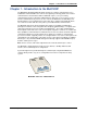
Chapter 1 - Introduction to the MultiVOIP Chapter 1 - Introduction to the MultiVOIP The MultiVOIP 100 (Model MVP120) allows analog voice and fax communication over a traditional IP network. Multi-Tech’s new voice/fax gateway technology allows voice and fax communication to be transmitted, with no additional expense, over your existing communications Internet, which has traditionally been data-only.
Chapter 1 - Introduction to the MultiVOIP Preview of This Guide This guide describes the MultiVOIP and tells you how to make the cable connections, install the software, and configure it. The information contained in each chapter is as follows: Chapter 1 - Introduction to the MultiVOIP This chapter describes the MultiVOIP features, a typical application, and the front and back panels.
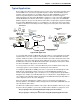
Chapter 1 - Introduction to the MultiVOIP Typical Application Before VOIP (Voice Over IP) technology existed, a sales office used a data connection to the Internet and a voice connection to the public telephone network. Now, with VOIP, the two networks can be tied together. To accomplish this a Sales Office MultiVOIP is connected between the public telephone network and the data network as shown in the typical application below.
Chapter 1 - Introduction to the MultiVOIP The H.323 Gatekeeper acts as the central point for all calls within its zone and provides call control services to registered endpoints. If you choose the proprietary phone book, you establish a master-slave relationship where the master MultiVOIP maintains the phone directory and downloads the directory to each slave unit. The Gatekeeper/Proprietary Phone Book selection is chosen from the Phone Directory Database dialog box.
Chapter 1 - Introduction to the MultiVOIP you use the same port number. The Gatekeeper administrator will then enter your information into the Gatekeeper data base. This concludes the preregisteration. You can enter your alias address information into the Add/Edit Phone Entry dialog box. For example, if you were setting up the corporate MultiVOIP, you could enter the following information for the Voice/Fax Channel: Channel 1 of the corporate MultiVOIP uses extension 101.
Chapter 1 - Introduction to the MultiVOIP Again, the corporate MultiVOIP IP Address needs to be added. The port number is 1720. This adds phone number 101 of the corporate MultiVOIP to the proprietary database. After you have added Channel 1, you need to include Channel 1 at the remote branch office.
Chapter 1 - Introduction to the MultiVOIP Similarly, if a person at the Remote Sales office picked up extension 201 and dialed extension 101, the MultiVOIP at the Sales Office would generate a second dial tone and the person at the Remote Sales office would then dial any extension at the Sales Office, or the person could then dial a 9, for example, and get an outside line of the Sales Office Public Switched Telephone network.
Chapter 1 - Introduction to the MultiVOIP Back Panel Description The cable connections for the MVP120 are made at the back panel. Connectors include Power, Ethernet, Command Port (RJ-45), and FXO Voice/Fax Channel. The cable connectors are shown and defined belos. POWER Power Connector ETHERNET COMMAND PHONE Ethernet Command (10BaseT) Port (RJ-45) Connector Connector Phone (RJ-11) Connector Back Panel Power Connector The Power connector is used to connect the external power supply to the MVP120.
Chapter 1 - Introduction to the MultiVOIP Specifications • One 4 MB DRAM (1 Meg by 32-bit, 70 nanosecond SIMM) Caution: SIMM speed and size cannot be mixed • Two Megabytes of flash memory Ethernet Port • Single Ethernet Interface - 10Base-T (twisted pair) keyed RJ-45 connector. Command Port • Single 19.
Voice / Fax over IP Networks 100 Chapter 2 Installation
Chapter 2 - Installation Chapter 2 - Installation Overview of the Installation Process The basic steps of installing your MVP120 network involve unpacking the units, connecting the cables, and configuring (Configuring is discussed in detail in Chapter 3) the units using the included management software (MultiVOIP Configuration). The recommended installation process includes four phases that, when completed, result in a fully functional Voice Over IP network.
Chapter 2 - Installation Unpacking Your MVP120 www.multitech.com Remove all items from the box. Voice/Fax over IP Networks CL MADE IN U.S .A U.S.A MADE IN Unpacking Telecom Safety Warning 1. 2. 3. 4. 5. 6. 7. 8. Never install phone wiring during a lightning storm. Never install phone jacks in wet locations unless the jacks are designed for wet locations. This product is to be used with UL and cUL listed computers.
Chapter 2 - Installation Cabling Your MVP120 Cabling your MVP120 involves making the proper Power, Command Port, and Network connections. The graphic below shows the back panel connectors and the associated cable connections. The Cabling Procedure section provides step-by-step instructions for cabling your MVP120. POWER ETHERNET COMMAND PHONE Cable Connections Cabling Procedure 1.
Voice / Fax over IP Networks 100 Chapter 3 Installing the MVP120 Software
Chapter 3 - Installing the MVP120 Software Chapter 3 - Installing the MVP120 Software The section covers the software installation. Note that not every screen or option in the process is included in this chapter. Additional information on the MVP120 software is provided in Chapter 4 and Chapter 5 and in the online Help. Note: The phonebook directory configuration process is different depending on whether or not you have an enabled H.323 Gatekeeper resident in your network.
Chapter 3 - Installing the MVP120 Software Press Enter or click Next to continue. 5. The Choose Destination Location dialog box displays. Follow the on-screen instructions. You can either choose the Destination Location of your MVP120 software or select the default destination by clicking Next. If you click Browse, you can select a different destination folder for the MVP120 software. 6. In the Select Program Folder dialog box, select where you want the program file to be located.
Chapter 3 - Installing the MVP120 Software Click OK to continue. 8. The Setup Complete dialog displays. Click Finish to continue. 9. The following message displays: Click Yes to continue. 10. The following message displays. Click Yes to continue. 11. The IP Protocol Default Setup dialog box displays as you continue now with the configuring of your MultiVOIP, which is continued in Chapter 4. Multi-Tech Systems, Inc.
Voice / Fax over IP Networks 100 Chapter 4 Configuring the Master MultiVOIP
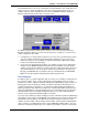
Chapter 4 - Configuring the Master MultiVOIP Chapter 4 - Configuring the Master MultiVOIP The following steps provide instructions for configuring your MVP120. The configuration sequence includes IP Protocol default setup, Channel setup, and Phone Directory Database setup. The numbering of steps continues from the previous section. 12. The IP Protocol Default Setup dialog box displays. The default Frame Type is TYPE_II. If this does not match your IP network, select SNAP from the Frame Type list.
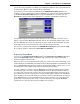
Chapter 4 - Configuring the Master MultiVOIP 15. The Ring Count FXO box enables you to set the number of rings received on the FXO interface before hanging up and releasing the line to another call. The default setting is 2 rings. Note: Zero (0) means no incoming calls will be answered. For FXO-to-FXO communications, you can enable a specific kind of FXO Disconnect Options: Current Loss, Tone Detection, or Silence Detection. Check with your in-house phone personnel to verify the type of disconnect to use.
Chapter 4 - Configuring the Master MultiVOIP If you changed the voice coder, ensure that the same voice coder is used on the voice/ fax channel you are calling. Otherwise, you will always get a busy signal. Note: If Automatic Coder is selected, then you need to select the Max Bandwidth from the list. Check with your Network Administrator to determine how much bandwidth is available. 19. The Fax group enables you to send/receive faxes on the selected voice/fax channel.
Chapter 4 - Configuring the Master MultiVOIP The Jitter Value defines the average inter-arrival packet deviation (in milliseconds) before the call is automatically disconnected. Jitter is the inter-arrival packet deviation (phase shift of digital pulses) over the transmission medium that causes voice breakup which can be particularly disruptive to voice communications. The default is 20 milliseconds. A higher value means that the voice transmission will be more accepting of jitter.
Chapter 4 - Configuring the Master MultiVOIP enables you to select either the GateKeeper or Proprietary PhoneBook. Once you have choosen the type of Phone Book database, you can proceed to registering with a Gatekeeper in the following section (entitled, Registering with a Gatekeeper Phone Directory). If you are building a proprietary phone book, proceed to page 31. On page 31 the Building a Proprietary Phonebook Directory section starts with Step 27. It is a continuation of Step 26 on this page.
Chapter 4 - Configuring the Master MultiVOIP 30. Accept the default Port Number 1719. CAUTION: The default setting for the Gatekeeper Port Number is 1719. This can be changed to a different value by the Gatekeeper administrator. If you decide to change the default Port Number, you must use the same number on the Gatekeeper and all other H.323 endpoints. 31. When you are finished with this dialog box, click Add to begin building your phone directory database. The Add/Edit Phone Entry dialog box displays.
Chapter 4 - Configuring the Master MultiVOIP 37. Click OK when you are finished and the Phone Directory Database dialog box displays with the first entry in the window. 38. Click OK. 39. The following dialog box displays. Click OK to download default setup. 40. After the setup has been written to the MVP120, the unit is rebooted. 41. Verify that the BOOT LED on the MVP120 is off after the download completes. This may take several minutes as the MVP120 reboots. Multi-Tech Systems, Inc.
Chapter 4 - Configuring the Master MultiVOIP Building a Proprietary Phonebook Directory Note: This section starts at Step 27 as it is a continuation from Step 26 on pages 27-28. 27. To build your proprietary MVP120 Phone Directory (in an H.323 environment without the Gatekeeper option enabled), you will first need to select the Proprietary Phonebook option and then configure the “Master” MVP120 and then the “Slave” MVP120s (or other H.323 endpoints).
Chapter 4 - Configuring the Master MultiVOIP 29. Enter a unique phone number for the local VOIP in the Phone Number box and enter 1 for the Voice/Fax channel in the Voice Channel box. This number must be 1 for each MVP120. Note: MVP120 and MVP110 will only have one entry and will be Channel 1. 30. The Description box is optional, but can be useful in associating the channel to the extension. If you wish, enter a description of your local phone number.
Chapter 4 - Configuring the Master MultiVOIP 33. Add all other phone numbers (slave units and standalone units) to the Phone Directory database. To add a channel of a slave MultiVOIP, click Add and the Add/Edit Phone Entry dialog box displays. 34. Enter the phone number for the MultiVOIP in the Station Information group Phone Number box. 35. Click inside the Description box and enter a description for the remote MultiVOIP phone number for the Voice/Fax Channel. 36.
Chapter 4 - Configuring the Master MultiVOIP 38. To configure a stand-alone endpoint (a PC with NetMeeting software), click Add and the Add/Edit Phone Entry dialog box displays again. 39. Enter the phone number for the stand-alone endpoint in the Station Information group Phone Number box. For example, 301. 40. Click inside the Description box and enter a description for the remote stand-alone phone number. For example, “Human Resources Desk”. Note: Because the H.
Chapter 4 - Configuring the Master MultiVOIP 43. When you have finished, click OK to download the setup configuration to the MVP120. 44. Click OK. After the setup is written to the MVP120, the unit reboots. 45. Verify that the BOOT LED on the MVP120 is off after the download is complete. This may take several minutes as the MVP120 reboots. At this time your master MVP120 is configured. Proceed to the “Configuring Your Slave MVP120s” section. Multi-Tech Systems, Inc.
Voice / Fax over IP Networks 100 Chapter 5 Configuring the Slave MultiVOIPs
Chapter 5 - Configuring the Slave MultiVOIPs Chapter 5 - Configuring the Slave MultiVOIPs If the Proprietary Phonebook option on the Phone Directory Database dialog box was enabled, then you will need to configure all remote H.323 endpoints as “Slave” units. For example, the MVP120 at the company’s subsidiary office in London would need to be configured as a “Slave.” CAUTION: If you are installing a MVP120 behind a Firewall, the Firewall must support H.323.
Chapter 5 - Configuring the Slave MultiVOIPs 4. In the Port Address group, enter the IP Address and IP Mask. In the Gateway Address group, enter the gateway IP address for the slave unit. The IP Address is the unique IP address that you assign to the MVP120, and the Gateway Address is the IP address of the device (such as a network router) connected to the Internet/ Intranet. Click OK when you are finished. The Main menu displays. 5.
Chapter 5 - Configuring the Slave MultiVOIPs 7. The Voice/Fax tab displays the parameters for the voice gain, DTMF (Dual Tone MultiFrequency) gain, voice coder, faxing, and advanced features such as Silence Compression, Echo Cancellation, and Forward Error Correction. 8. Input gain modifies the level of the audio coming in to the voice channel before it is sent over the Internet to the remote MVP120. Output gain modifies the level of the audio being output to the device attached to the voice channel.
Chapter 5 - Configuring the Slave MultiVOIPs 11. You can enable the voice/fax advanced features by clicking (checking) the silence compression, echo cancellation, or forward error correction options. Silence Compression - Defines whether silence compression is enabled for the voice channel. If silence compression is enabled, the MVP120 will not transmit voice packets when silence is detected, thereby reducing the amount of network bandwidth that is being used by the voice channel.
Chapter 5 - Configuring the Slave MultiVOIPs Call Duration defines the maximum length of time (in seconds) that a call remains connected before the call is automatically disconnected. The default setting is 180 seconds. A call limit of three minutes may be too short for most configurations. Therefore, you may want to increase this default value. 14.
Chapter 5 - Configuring the Slave MultiVOIPs Note: After you have enabled the Slave option, the Slave Status button is replaced by the Update button. Once your Phone Directory database has been established, you can click this button to refresh the entries in the Phone Directory Database window. 18. Enter the IP address (204.022.122.118) of the New York Office MVP120 in the Master IP Address box and enable the Send Status Report to Master so that status reports are sent to the Master MVP120.
Voice / Fax over IP Networks 100 Chapter 6 Deploying the VOIP Network
Chapter 6 - Deploying the VOIP Network Chapter 6 - Deploying the VOIP Network For a Proprietary Phone Directory database, the VOIP administrator can deploy the preconfigured slave MVP120s to their remote sites. The remote site administrators need only connect power to the pre-configured MVP120, connect the MVP120 to the Ethernet LAN and predefined telephone equipment, and then wait for the phone directory database to be downloaded.
Voice / Fax over IP Networks 100 Chapter 7 Using the MultiVOIP Software
Chapter 7 - Using the MultiVOIP Software Chapter 7 - Using the MultiVOIP Software This chapter describes various features of the MVP120 software that enable you to change the configuration of your MVP120. The default configuration parameters were entered during the loading of the software. The MVP120 software and configuration utilities described in this chapter enable you to change that initial configuration as necessary.
Chapter 7 - Using the MultiVOIP Software MVP120 Configuration The MVP120 Setup menu consists of 10 buttons, an Events window in the middle of the menu, and a status bar at the bottom of the menu. The 10 buttons allow you to display and change the voice channels and IP protocol parameters, display and manage the Phone Book listing, view statistics and call progress, and change features such as SNMP Agent, Telnet Server, WEB Server, and assign a MVP120 password.
Chapter 7 - Using the MultiVOIP Software Changing Channel Parameters The channel parameters include the interface type and its options, voice and fax settings, billing and security, and voice communications for the country and region in which the MVP120 is operating. The Channel Setup dialog box, accessed by clicking Voice Channels on the Setup menu, has four tabs that display the following categories of channel information -- Interface, Voice/Fax, Billing/Misc, and Regional.
Chapter 7 - Using the MultiVOIP Software For FXO-to-FXO communications, you can enable a specific kind of FXO Disconnect Options: Current Loss, Tone Detection, or Silence Detection. Check with your in-house phone personnel to verify the type of disconnect to use. If current lossis checked, the VOIP will hang up when it detects a loss of current on the FXO (phone) port. For tone detection, select from the lists one or two tones that will cause the line to disconnect.
Chapter 7 - Using the MultiVOIP Software The Fax group enables a fax machine to transmit and receive faxes through the MVP120. If a fax machine is connected to the via PBX port or PTSN, the Max Baud Rate should be set to match the baud rate of the fax machine (refer to user documentation). The Fax Volume setting controls the output level of the fax tones, and this setting should be changed only under the direction of Multi-Tech’s Technical Support personnel.
Chapter 7 - Using the MultiVOIP Software Billing Options can be used to track the cost of Inbound and/or Outbound calls on the FXO interface. The amount to be charged in cents is entered in the Charge ( ) Cents box together with the associated time duration in the Per ( ) Seconds box. While a given call is active, the accumulated charges can then be viewed on the Call Progress dialog box.
Chapter 7 - Using the MultiVOIP Software Changing the Phone Directory Database The MultiVOIP provides two phone directory database architectures; the propreitary database and a database using an H.323 protocol gatekeeper that provides a centralized call control center. The gatekeeper centralized call control center contains the phone directory database when all VOIP gateways and endpoints support the H.323 protocol.
Chapter 7 - Using the MultiVOIP Software Proprietary Phone Directory Database In the Proprietary Phone Directory Database, you can add, delete, or edit any entry in the phone directory database and you can set up Hunt groups that locate another phone number if the called number is busy. You can print the phone directory database so that you have a hardcopy of the phone directory. To add an entry to the Phone Directory database, click Add and the Add/Edit Phone Entry dialog box displays.
Chapter 7 - Using the MultiVOIP Software The Station Identification group enables you to assign the entry to a Hunt Group, provide the IP Address of the MultiVOIP being assigned the phone number, and accept the H.323 industry standard Port number. A Hunt Group is a series of telephone lines organized in such a way that if the first line is busy the next line is hunted and so on until a free line is found.
Chapter 7 - Using the MultiVOIP Software Gatekeeper Phone Directory Database With the Gatekeeper Phone Directory Database, the Gatekeeper acts as the central point for all calls within its zone and provides call control services to registered endpoints. The Gatekeeper performs address translation from LAN aliases to IP addresses and provides bandwidth management where the network manager has specified a threshold for the number of simultaneous calls on the LAN. The H.323 ID is an alias.
Chapter 7 - Using the MultiVOIP Software The Add/Edit Phone Entry dialog box contains two groups of information: 1. Station Information which contains the phone number, description window which can be left blank, and the voice channel number. Station Identification group contains the H.323 ID and the IP Address window for the IP Address of the MultiVOIP assigned the phone number, and the Port number of the MultiVOIP unit communicating with the Gatekeeper.
Chapter 7 - Using the MultiVOIP Software Changing IP Parameters The IP Setup dialog box establishes the IP address for the local Ethernet LAN and defines the Internet gateway address. The IP Setup dialog box is accessed by clicking IP on the MVP120 Main menu. With IP Setup dialog box displayed you can change the status of Diffserv, the Ethernet Frame Type, the IP address and IP Mask of your H.323 endpoint, and the Gateway Address of the IP address of the device connected to the Internet.
Chapter 7 - Using the MultiVOIP Software The Frame Type list enables you to change the Ethernet Frame Type so that it matches your IP network. If the current entry does not match your IP network, select the Frame Type from the Frame Type list. The Frame Type choices are TYPE_II and SNAP. The Port Address group enables you to change the unique IP Address and IP Mask of the local LAN. The Gateway Address group enables you to change the gateway IP Address of the device connected to the Internet/Intranet.
Chapter 7 - Using the MultiVOIP Software Applications Setup Clicking Others on the Setup menu displays the Applications Setup dialog box. This dialog box allows you to enable SNMP Agent (the default is disabled) and set up all the necessary parameters; enable or disable various remote configuration methods such as TFTP (Trivial File Transfer Protocol) Server, Web Server, Dumb Terminal Management, and Telnet Server; and assign a Password to the MVP120 for security.
Chapter 7 - Using the MultiVOIP Software Viewing Statistics The Statistics dialog box enables you to view statistics for major events of the MVP120 operation. This dialog box is accessed by clicking Statistics on the MVP120 Main menu. The Voice Channel statistics shows the attempted and completed calls, call duration, average call length, bytes/packets sent and received. These statistics can be a helpful troubleshooting tool.
Chapter 7 - Using the MultiVOIP Software connecting to the MVP120’s web server, you would look under the TCP section to see if any connections are being established. If not, that may indicate the web server is not enabled. Or, if you were having problems establishing a remote connection through TFTP, you could look in the UDP section to see if any packets are being received. If not, you may need to review your network addressing.
Chapter 7 - Using the MultiVOIP Software Viewing Logs The Log Entries dialog box displays a chronological history of all calls into and out of this unit. This dialog box is opened by clicking Logs on the Statistics dialog box. The Log Entries dialog box displays each call as a sequentially numbered Event with the date, time, duration of the call, the status of the call (Successful or Unsuccessful), Mode (Voice or Fax), and the from and to numbers.
Chapter 7 - Using the MultiVOIP Software Viewing Channel Totals The Channel Totals dialog box displays Outgoing and Incoming calls with their Attempted and Completed numbers for each channel on this MVP120. The Total Connected Time for the channel is also displayed. This can provide you with a sense of successful call completions on each channel of the unit.
Chapter 7 - Using the MultiVOIP Software Upgrade Procedures Whenever you upgrade your version of the MVP120 software, you must first install the new software on your PC. Then use the Upgrade Software function, the Factory Defaults, or download the Firmware, the Voice Coders, and the H.323 stack to upgrade the MVP120 itself.
Chapter 7 - Using the MultiVOIP Software 5. Click OK when finished. The Checking MultiVOIP dialog box displays. When you click OK in this box, theThe MultiVOIP firmware, voice coders, and H.323 stack are downloaded, and then the MVP120 reboots. Upgraded versions of the Boot Code (firmware, coders, and H.323 stack) can be downloaded individually using the following manual procedures. Multi-Tech Systems, Inc.
Chapter 7 - Using the MultiVOIP Software Manual Upgrade Procedure Follow this procedure only if you want to manually upgrade your MultiVOIP. Note: Steps 4-8 may be performed via the command port or over IP. 1. Run MultiVOIP Configuration from your old version of the MultiVOIP software. Note the current settings. Your MultiVOIP will be reset to factory defaults during this upgrade. 2.
Voice / Fax over IP Networks 100 Chapter 8 Remote Configuration and Management
Chapter 8 - Remote Configuration and Management Chapter 8 - Remote Configuration and Management This chapter provides procedures for viewing or changing the configuration of a remote unit. Two methods are provided to access a remote unit; the first method is modem based and the second method uses IP. Within the IP method, three applications can be used: 1) LAN-Based using TFTP (Trivial File Transfer Protocol), 2) Telnet as a client application, or 3) a standard web browser on the Internet.
Chapter 8 - Remote Configuration and Management In the Dial String box, enter the AT command for dialing (ATDT) plus the phone number of the remote MVP120. If your Modem Initialization String, Initialization Response, or Connect Response values are different from the defaults in the dialog box, refer to your modem user documentation and change the default values to match your modem. Click OK when you are satisfied with your selections. 6. Run the MVP120 Configuration program.
Chapter 8 - Remote Configuration and Management LAN-Based The LAN-based remote configuration requires a Windows Sockets compliant TCP/IP stack. TCP/IP protocol software must be installed and functional before the configuration program can be used. 1. You must assign an Internet (IP) address for the PC and for each node that will be managed by the configuration program. Refer to the protocol software documentation for instructions on how to set the IP addresses.
Chapter 8 - Remote Configuration and Management 7. After you have changed the configuration of the remote MultiVOIP , click Download Setup to update the configuration. The remote MultiVOIP will be brought down, the new configuration written to the unit, and the unit will reboot. 8. Click Exit when downloading is complete. 9. Double-click the MultiVOIP Configuration icon in the MultiVOIP 100 program group to verify that the MultiVOIP is running. Multi-Tech Systems, Inc.
Chapter 8 - Remote Configuration and Management Telnet A typical Telnet client application is described next. The MVP120 has a built-in Telnet Server that enables Telnet client PCs to access the MVP120. A typical Telnet client is allowed to configure the MVP120. In addition, the MVP120 can be remotely accessed and configured from anywhere on the Internet through its Web interface. The Telnet Server option has to be selected from the Applications Setup dialog box using the MultiVOIP 100 Configuration icon.
Chapter 8 - Remote Configuration and Management Web Management The MVP120 can be accessed, via a standard Web browser, from anywhere on the connected Internet. In order to provide this support, the WEB Server option has to be enabled from the Applications Setup dialog box (see Chapter 4 - MVP120 Software). Once enabled, you can access the MVP120 by entering its IP address in your web browser. The following page displays.
Voice / Fax over IP Networks 100 Chapter 9 Warranty, Service, and Technical Support
Chapter 9 - Warranty, Service, and Technical Support Chapter 9 - Warranty, Service, and Technical Support This chapter starts out with statements about your MVP120 2-year warranty. The next section, Tech Support, should be read carefully if you have questions or problems with your MVP120. It includes the technical support phone numbers, space for recording your product information, and an explanation of how to send in your MVP120 should you require service.
Chapter 9 - Warranty, Service, and Technical Support Please direct your questions regarding technical matters, product configuration, verification that the product is defective, etc., to our Technical Support department at (800) 972-2439 or email tsupport@multitech.com. Please direct your questions regarding repair expediting, receiving, shipping, billing, etc., to our Repair Accounting department at (800) 328-9717 or (763) 717-5631, or email mtsrepair@multitech.com.
Chapter 9 - Warranty, Service, and Technical Support Service If your tech support specialist decides that service is required, your MVP120 may be sent (freight prepaid) to our factory. Return shipping charges will be paid by Multi-Tech Systems.
Chapter 9 - Warranty, Service, and Technical Support Technical Support Multi-Tech has an excellent staff of technical support personnel available to help you get the most out of your Multi-Tech product. If you have any questions about the operation of this unit, call 1800-972-2439. Please fill out the MVP120 information (below), and have it available when you call. If your MVP120 requires service, the tech support specialist will guide you on how to send it in (refer to the next section).
Voice / Fax over IP Networks 100 Appendixes
Appendix A - TCP/IP Description Appendix A - TCP/IP Description TCP/IP (Transmission Control Protocol/Internet Protocol) is a protocol suite and related applications developed for the U.S. Department of Defense in the 1970s and 1980s specifically to permit different types of computers to communicate and exchange information with one another. TCP/IP is currently mandated as an official U.S. Department of Defense protocol and is also widely used in the UNIX community.
Appendix A - TCP/IP Description UDP, described in RFC 768 (ftp://ds.internic.net/rfc/rfc768.txt) provides an end-to-end datagram (connectionless) service. Some applications, such as those that involve a simple query and response, are better suited to the datagram service of UDP because there is no time lost to virtual circuit establishment and termination. UDP’s primary function is to add a port number to the IP address to provide a socket for the application.
Appendix A - TCP/IP Description Internet Protocol (IP) IP is the Internet standard protocol that tracks Internetwork node addresses, routes outgoing messages and recognizes incoming messages, allowing a message to cross multiple networks on the way to its final destination. The IPv6 Control Protocol (IPV6CP) is responsible for configuring, enabling, and disabling the IPv6 protocol modules on both ends of the point-to-point link.
Appendix B - Cabling Diagrams Appendix B - Cabling Diagrams Command Port Cable 1 2 3 4 5 6 7 8 RJ-45 DB9F 1 4 2 7 3 8 CLEAR TO SEND 4 3 TRANSMIT DATA 5 2 RECEIVE DATA 6 6 7 1 8 5 PIN NO. To Command Port Connector PIN NO.
Appendix B - Cabling Diagrams Remote Configuration Cable 9-Pin Male To Command port adapter cable 25-Pin Male To DCE Device (e.g., modem) Receive Data (RX) 2 2 Receive Data (RX) Transmit Data (TX) 3 3 Transmit Data (TX) Signal Ground 5 7 Signal Ground Clear to Send (CTS) 8 4 Request to Send (RTS) Multi-Tech Systems, Inc.
Appendix C - Regulatory Information Appendix C - Regulatory Information Class A Statement FCC Part 15 NOTE: This equipment has been tested and found to comply with the limits for a Class A digital device, pursuant to Part 15 of the FCC Rules. These limits are designed to provide reasonable protection against harmful interference when the equipment is operated in a commercial environment.
Appendix C - Regulatory Information FCC Part 68 Telecom 1. This equipment complies with Part 68 of the Federal Communications Commission (FCC) rules. On the outside surface of this equipment is a label that contains, among other information, the FCC registration number and ringer equivalence number (REN). If requested, this information must be provided to the telephone company. 2. As indicated below, the suitable jack (Universal Service Order Code connecting arrangement) for this equipment is shown.
Appendix C - Regulatory Information Canadian Limitations Notice Ringer Equivalence Number Notice: The ringer equivalence number (REN) assigned to each terminal device provides an indication of the maximum number of terminals allowed to be connected to a phone interface. The termination on an interface may consist of any combination of devices subject only to the requirement that the sum of the ringer equivalence numbers of all the devices does not exceed 5.
Voice / Fax over IP Networks 100 Glossary
Glossary Glossary A Access: The T1 line element made up of two pairs of wire that the phone company brings to the customer premises. The Access portion ends with a connection at the local telco (LEC or RBOC). Accunet Spectrum of Digital Services (ASDS): The AT&T 56K bps leased (private) line service. Similar to services of MCI and Sprint. ASDS is available in nx56/64K bps, where n=1, 2, 4, 6, 8, 12.
Glossary Backward Explicit Congestion Notification (BECN): A bit that tells you that a certain frame on a particular logical connection has encountered heavy traffic. The bit provides notification that congestion-avoidance procedures should be initiated in the opposite direction of the received frame. See also FECN (Forward Explicit Congestion Notification). Basic Rate Interface (BRI): An ISDN access interface type comprised of two B-channels each at 64K bps and one D-channel at 64K bps (2B+D).
Glossary Centrex: A multi-line service offered by operating telcos which provides, from the telco CO, functions and features comparable to those of a PBX for large business users. See also "Private Branch Exchange", "Exchange". Channel: A data communications path between two computer devices. Can refer to a physical medium (e.g., UTP or coax), or to a specific carrier frequency.
Data Communications Equipment (DCE): Any device which serves as the portal of entry from the user equipment to a telecommunications facility. A modem is a DCE for the phone network (PSTN) that is commonly on site at the user’s premises. Packet Switched Networks have another level of DCE which is most often located at a central office. Data Link Connection Identifier (DLCI): One of the six components of a frame relay frame.
Glossary EIA: The Electronics Industries Association is a trade organization in Washington, DC that sets standard for use of its member companies. (See RS-232, RS-422, RS530.) Encapsulation: A technique used by network-layer protocols in which a layer adds header information to the protocol data unit from the preceding layer. Also used in "enveloping" one protocol inside another for transmission. For example, IP inside IPX. Endpoint: The clients in an H.323 network.
Foreign Exchange Station (FXS): See FX, FXO. To generate a call from the computer telephony system to the POTS set, a FXS connection must be configured. Forward Explicit Congestion Notification (FECN): A bit that tells you that a certain frame on a particular logical connection has encountered heavy traffic. The bit provides notification that congestion-avoidance procedures should be initiated in the same direction of the received frame. See also BECN (Backward Explicit Congestion Notification).
Glossary Inter Exchange Carrier (IEC): The long distance company (LE) who's central office provides the point of reference for T1 access. Any common carrier authorized by the FCC to carry customer transmissions between LATAs. Internet: Refers to the computer network of many millions of university, government and private users around the world. Each user has a unique Internet Address. Internet Address (IP Address): A unique 32-bit address for a specific TCP/IP host on a network.
Local Access and Transport Area (LATA): A post-divestiture geographical area generally equivalent to a Standard Metropolitan Statistical Area. At divestiture, the territory served by the Bell system was divided into approximately 161 LATAs. The Bell Operating Companies (BOCs) provide Intra-LATA services. Local Exchange Carrier (LEC): The local phone company which provides local (i.e., not long distance) transmission services. AKA "telco".
Glossary Network: A group of computers connected by cables or other means and using software that enables them to share equipment, such as printers and disk drives to exchange information. Node: Any point within a network which has been assigned an address. O Object-Orientated: A method for structuring programs as hierarchically organized classes describing the data and operations of objects that may interact with other objects.
PRI (Primary Rate Interface): Used on ISDN. In North America, and Japan, PRI is one 64Kbps D channel and 23 B channels. Elsewhere, it is one D channel and 30 B channels. PRI is the ISDN equivalent of a T-1 circuit. Primitive: An abstract representation of interaction across the access points indicating that information is being passed between the service user and the service provider. The OSI Reference Model defines four types of primitives: Request, Indication, Response and Confirm.
Glossary Router: A device that connects two networks using the same networking protocol. It operates at the Network Layer (Layer 3) of the OSI model for forwarding decisions. Routing Information Protocol (RIP): A distance vector-based protocol that provides a measure of distance, or hops, from a transmitting workstation to a receiving workstation. RS-232-C: An EIA standard for a serial interface between computers and peripheral devices (modem, mouse, etc.). It uses a 25pin DB-25, or a 9-pin DB-9 connector.
Glossary T Tariff: The rate/availability schedule for telephone and ISDN services from a regulated service provider. TCP/IP: A set of communication protocols that support peer-to-peer connectivity functions for both local and wide area networks. TCP/IP was developed by the US Department of Defense to link dissimilar computers across dissimilar and unreliable LANs. T Carrier: The generic name for a digitally multiplexed carrier system.
Glossary Trunk: A communication line between two switching systems or offices. Central office trunks connect a PBX to the switching system at the central office. A tie trunk connects two PBXs. TSR (terminate and stay resident): A software program that remains active and in memory after its user interface is closed. Similar to a daemon in UNIX environments. Tunneling: Encapsulation data in an IP packet for transport across the Internet.
Index E Index A About the Internet ........................................... Accessories, ordering ..................................... Add/Edit Phone Entry ..................................... Applications setup, changing .......................... Archie ............................................................. Auto Call ................................................... 40, Auto Call Enable ....................................... 26, Automatic Disconnection ..........................
Index L LAN cable, diagram ........................................ LAN-based remote configuration .................... LEDs 56K DSU RD ........................................................... Ethernet CL ........................................................... LNK ......................................................... RD ........................................................... TD ........................................................... Log entries, reports ..................................
Index U UDP packets .................................................. Uninstall ProxyServer configuration ............... Unpacking your MVP120 ............................... Upgrading software version ............................ 60 46 17 64 V Viewing statistics ............................................ Voice coder, voice/fax .................................... Voice over IP configuration ............................. Voice/Fax 1 and 2, front panel ........................