Model RF500S Broadband Router User Guide
User Guide Broadband Router Model RF500S PN S000125D Revision D Copyright This publication may not be reproduced, in whole or in part, without prior expressed written permission from Multi-Tech Systems, Inc. All rights reserved. Copyright © 2001by Multi Tech Systems, Inc. Multi-Tech Systems, Inc. makes no representations or warranties with respect to the content hereof and specifically disclaims any implied warranties of merchantability or fitness for any particular purpose.
Table of Contents Contents Contents ...................................................................................................................... 3 Chapter 1 - Introduction ............................................................................................. 6 RF500S Front Panel ................................................................................................... 7 Back Panel .....................................................................................................
Table of Contents Save Settings to File................................................................................................. 99 Load Settings.......................................................................................................... 100 Upgrade Firmware .................................................................................................. 101 General Diagnostic .................................................................................................
Chapter 1 Introduction RouteFinder RF500S User Guide 5
Chapter 1 – Introduction Chapter 1 - Introduction Welcome to the world of broadband connectivity to the Internet. The Multi-Tech Broadband RouteFinder connects a cable modem or DSL modem to an Ethernet LAN to provide high-speed broadband access to the Internet for up to 253 users. The Broadband Router features a built-in 4-port 10/100M bps switch, one asynchronous port for backup Internet access or dial-in remote access, firewall services, and network security.
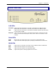
Chapter 1 – Introduction RF500S Front Panel LAN LEDs Link/ACT Lights when the LAN client is correctly connected to the Ethernet port. Blinks when the LAN client is correctly connected to the Ethernet port. 100 Lights when the LAN client is connected at 100MB. Off when the LAN client is connected at 10MB. FDX/COL Lights when the LAN client is connected as full duplex. Off when the LAN client is connected as half duplex. Blinks when there are collisions on the network.
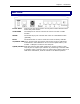
Chapter 1 – Introduction Back Panel Power 5VDC Connect one end of the power cord to power socket and the other end to the power outlet. 10 BT WAN The WAN port is used to connect the router to a DSL or Cable modem. ASYNC The Serial async port connects the router to a standard modem (optional). Reset The Reset button is used to reset the router to factory defaults. 10/100 BT LAN The 4-10/100 ports are used to connect the router to LAN client workstations.
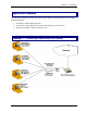
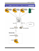
Chapter 1 – Introduction Application Examples The following examples provide information about RF500S typical applications. The three examples include: 1. Connecting a local LAN to Internet. 2. Connecting a local LAN to the Internet and setting up a remote site. 3. Setting up a LAN to LAN via the Async Port.
Chapter 1 – Introduction Example 2 – Local LAN to Internet / Remote Site RouteFinder RF500S User Guide 10
Chapter 1 – Introduction Example 3 – LAN to LAN via an Async Port Note: Set the modem type to leased line.
Chapter 1 – Introduction Setup for Example 3 The setup describes the RF500S used as routers to route IP traffic between two LANs. Network Addresses LAN A IP Network Address: 192.168.2.x WAN IP Network Address: 10.10.10.x LAN B IP Network Address: 192.168.100.x Note: Between LAN A and LAN B Are Two RF500S RouteFinders and One 56K LAN A RF500S WAN Ethernet port in this case is not used 95/98 Workstation has IP Address: 192.168.2.2 RF500S 10/100 Ethernet port has IP Address: 192.168.2.
Chapter 1 – Introduction Check Assign Remote Site an IP Address and enter the IP Address: 192.168.100.2 Check Allow Remote Dial-in Click the Remote Authentication Settings button if you want to authenticate with user name and password. The Remote Connection Authentication screen displays. Remote Connection Authentication Screen If you check PAP, then check Use Local Settings and enter the Remote User Name and Remote Password. Click the OK button and return to the RouteFinder Manager main menu. 4.
Chapter 1 – Introduction Check Assign Remote Site an IP Address and enter the IP Address: 192.168.100.1 Check Allow Remote Dial-in Click the Remote Authentication Settings button if you want to authenticate with user name and password. The Remote Connection Authentication screen displays. Remote Connection Authentication Screen If you check PAP, then check Use Local Settings and enter the Remote User Name and Remote Password. Click the OK button and return to the RouteFinder Manager main menu. 4.
Chapter 1 – Introduction Specifications Hardware ARM RISC CPU32 bit, 40MHZ 4MB DRAM and 512k Flash ROM UART Serial port controller LAN Ports Number of Ports: 4 Interface: 10Base T/100BaseTX, - One port can be used for uplink Standard: 802.3 WAN Ports 1 x 10BaseT 1 x RS232 (V.24) DTE Speed: Up to 460K asynchronous Protocols Security: PAP/CHAP, MSCHAP, NAT Firewall, RADIUS and Callback for remote access.
Chapter 2 Hardware Installation RouteFinder RF500S User Guide 16
Chapter 2 – Hardware Installation Chapter 2 - Hardware Installation Safety 1. Never install telephone wiring during a lightning storm. 2. Never install telephone jacks in a wet location unless the jack is specifically designed for wet locations. 3. This product is to be used with UL and cUL listed computers. 4. Never touch uninsulated telephone wires or terminals unless the telephone line has been disconnected at the network interface. 5. Avoid using a telephone during an electrical storm.
Chapter 2 – Hardware Installation Cabling Cabling your RouteFinder requires making the appropriate connections to PCs, Cable or DSL modem, analog modem or ISDN TA (optional), AC power, and the RouteFinder. Then, after your device is properly cabled, you will have to configure your RouteFinder. Follow the instructions provided in the Web Browser Configuration and Management chapter.
Chapter 2 – Hardware Installation Cabling Directions Before beginning, turn the power off on all network devices (PCs, Cable/xDSL modems, analog modems, ISDN TAs, and the router). 1. Connect the Ethernet port of each PC or network device to one of the 4 LAN ports. Important: If you are using the Uplink option, Port Number 1 cannot be used as a LAN port). 2. If you are using an analog modem, connect it to the Serial Async port. 3.
Chapter 3 Web Browser Configuration And Management RouteFinder RF500S User Guide 20
Chapter 3 – Configure and Manage Using a Web Browser Chapter 3 – Configure and Manage Using a Web Browser Overview of Configuration and Management The RF500S can be configured and managed using one of two methods. 1. Using a Web Browser: Launch your Web browser and type the device IP address http://192.168.2.1 in the browser address box. This IP address is the default value of your gateway. Press Enter. The RouteFinder wizard main screen displays.
Chapter 3 – Configure and Manage Using a Web Browser Using the Web Browser Launch your Web browser and type the device IP address (http:// 192.168.2.1) in the browser’s address box. This IP address is the default value of your gateway. Press Enter. Note: Make sure your PC’s address is in the same network as the router’s. In Windows 95/98/Me you can type WINIPCFG. In Windows 2000/NT, you can type IPCONFIG. The main menu displays.
Chapter 3 – Configure and Manage Using a Web Browser Setup Wizard To access, click the Setup Wizard button on the main screen. The Setup Wizard is a step-by-step process for configuring your RouteFinder. The Enter Network Password screen displays. Type admin (the default user name) in the user name box and leave the password box empty. Click OK. Note: For information on how to change your password, see the ISP Additional Settings section. The Setup Wizard screen then displays.
Chapter 3 – Configure and Manage Using a Web Browser Setup Wizard Screen – Time Zone Selection Choose the local time zone (see screen above). Select the time zone, and then click the Next button to continue. You can also click the buttons on the left side of the screen. These buttons are useful when you want to change the information on individual screens or to choose your own setup order.
Chapter 3 – Configure and Manage Using a Web Browser – Device IP Settings You must set your Internet gateway an IP address on your network. This is not the IP address from your ISP but the local internet LAN IP address. The IP address 192.168.2.1 is the default value of your gateway. Device IP Address The internal LAN IP address of your Internet gateway. Device IP Subnet Mask The subnet mask can usually be left as its default entry 255.255.255.
Chapter 3 – Configure and Manage Using a Web Browser – Cable/xDSL ISP Settings If you would like to establish Cable/xDSL ISP settings, you have to enable this function by configuring this screen. Some ISPs may give you Static IP settings. If this is the case for your ISP, then you need to: Enter the IP address that is assigned by your ISP. Enter the IP subnet mask. Enter the ISP gateway address. Enter the DNS IP address.
Chapter 3 – Configure and Manage Using a Web Browser – ISP Additional Settings (PPPoE Settings) Some ISPs use this protocol for authentication purposes. If applicable: Enter the User Name of your ISP account. Enter the Password of your ISP account. To verify your password, Retype the Password of your ISP account. Some ISPs require additional information; if this is the case: Enter the Host Name to authenticate the user. Enter the LAN card MAC address.
Chapter 3 – Configure and Manage Using a Web Browser – Modem Settings A modem can be used as a dialup backup to the Cable/xDSL connection. If you would like to use a modem backup, enable the modem settings function. Check the Dialup Modem When Cable/xDSL Is Not Connected box. Then input the ISP account settings. Note: If you change the baud rate settings, please check the initial string. (You can refer to your modem manual or TA.
Chapter 3 – Configure and Manage Using a Web Browser Device Information Click the Device Information button. The Device Information screen displays the current settings of the RF500S. Device Name – The host name of the Internet gateway. IP Address – The IP address of the Internet gateway. Private LAN Mac Address – The Mac address of the Internet gateway LAN Ethernet port. This address cannot be changed; it is assigned by Multi-Tech.
Chapter 3 – Configure and Manage Using a Web Browser Device Status Click the Device Status button. The Device Status screen displays. The Device Status screen displays the status of the current connection. It shows the status of the Cable/xDSL modem and the Modem Backup. It also shows the IP Address, the LAN Mac Address, and the WAN Mac Address. WAN Ethernet – This describes the current connection status of the Cable/xDSL Modem.
Chapter 3 – Configure and Manage Using a Web Browser Advanced Settings Click the Advanced Settings button. The DHCP Server Settings screen displays. Advanced Settings options will establish DHCP server settings, virtual server settings, a static routing table, dynamic settings, modem string settings, administrative settings. DHCP Server Settings The DHCP Server is enabled by default. If you would like to disable it, uncheck the Enable DHCP Server Functions box.
Chapter 3 – Configure and Manage Using a Web Browser – Virtual Server Settings To access this screen, click the Virtual Server Settings button on the left side of the screen. Virtual Server Settings allow clients on the Internet to access your LAN via the Internet. You can use the IP mapping function to access an FTP server or Telnet server, etc. on your LAN via your ISP Internet connection. If applicable, enter a DMZ address. Enter the Internal IP number and the Service Port Range for each client.
Chapter 3 – Configure and Manage Using a Web Browser – Static Routing Routing is the process of moving packets of data from source to destination. Use this screen to create a routing table to connect your network to another, or to connect subnets within your network. 1. To access this screen, click the Static Routing button on the left side of the screen. The Static Routing Table screen displays. 2. Enter the details for each entry in the routing table. Click the Add button after each entry.
Chapter 3 – Configure and Manage Using a Web Browser – Dynamic Routing Dynamic Routing is disabled when Static Routing is used. You will have to disable Static Routing in order to choose one of the dynamic routing protocols. The Dynamic Routing protocol adjusts automatically to the changes in the network topology or traffic. 1. To access this screen, click the Dynamic Routing button on the left side of the screen. The Dynamic Settings screen displays. 2.
Chapter 3 – Configure and Manage Using a Web Browser – Filter Settings The LAN Filter Settings function allows the network administrator to define whether local users have the permission to access the Internet. 1. To access this screen, click the Filter Settings button on the left side of the Advanced Settings screen. 2. Check the LAN Side Filter Enabled box to begin a list of users and permissions. 3. Select the LAN side filter: Block or Pass. 4. Select the client filter settings: Block or Pass. 5.
Chapter 3 – Configure and Manage Using a Web Browser – WAN Filter Settings The WAN Filter Settings function allows the network administrator to define whether remote/outside users have the permission to access the local network. To activate, check the WAN Side Filter Enabled box. Then define the policy. 1. To access this screen, click the Filter Settings button on the left side of the Advanced Settings screen. Then click the WAN Filter Settings button on the left side of the screen.
Chapter 3 – Configure and Manage Using a Web Browser – Modem String Settings Use the Modem String Settings screen to establish settings for your modem and to set the baud rate. 1. To access this screen, click the Modem String Settings button on the left side of the Advanced Settings screen. The Modem Settings screen displays. 2. Select the baud rate from the drop-down list box. If you want to change the baud rate, check the initial string. Refer to the manual that accompanied your modem or TA. 3.
Chapter 3 – Configure and Manage Using a Web Browser – Administrative Settings Use this screen to change your RF500S password, set the HTTP port number, set remote user configuration, and establish system log settings. 1. To access this screen, click the Administrative Settings button on the left side of the Advanced Settings screen. 2. Password: To set a new password, type the new one in the New Password box and re-type it for verification in the Retype Password box.
Chapter 3 – Configure and Manage Using a Web Browser 7. When you have completed the screen, click the Submit button.
Chapter 3 – Configure and Manage Using a Web Browser System Tools Click the Systems Tools button on the Main Menu. The Intruder Detection Log displays first. System Tools allow you to view the Intruder Detection Log, the Routing Table, and a System Diagnosis screen. You can also choose to save your settings, load the RF500S default settings, upgrade firmware, and reset the device. Intruder Detection Log The event messages show the possible hacker attacks that have occurred on your Internet gateway.
Chapter 3 – Configure and Manage Using a Web Browser – Display Routing Table This table shows the current routing configuration that you setup on the Routing Table screen. 1. To access this screen, click the Display Routing Table button from the System Tools screen. The Display Routing Table screen displays. 2. To exit this screen, select another button on the left side of the screen.
Chapter 3 – Configure and Manage Using a Web Browser – System Diagnosis When selected, the System Diagnosis function performs a check-up on your RF500S to make sure that everything is functioning properly.
Chapter 3 – Configure and Manage Using a Web Browser – Saving Your Settings to a File Use this screen to save your configuration settings to a file. This will provide a backup of your settings in case, for some reason, you have to reset your RF500S. 1. Click the Save File button in the middle of the screen. 2. Then click Save This File to Disk in the browsing wizard.
Chapter 3 – Configure and Manage Using a Web Browser – Load Default Settings Use this screen to load the original RF500S factory defaults. 1. To access this screen, click the Load Default Settings button from the System Tools screen. The Load Default Settings screen displays. 2. Click the Start button to load the default settings. – Load Settings from a File 1. To load settings from a file, click the Load Settings From File button. The screen displays. 2. Select the browse button to locate the file. 3.
Chapter 3 – Configure and Manage Using a Web Browser – Upgrade Firmware The Upgrade Firmware option allows you to upgrade the newest firmware to your RF500S. How will I be notified of new router firmware upgrades? All Multi-Tech firmware upgrades are posted on the Multi-Tech Web site at www.multitech.com, where they can be downloaded for free.
Chapter 3 – Configure and Manage Using a Web Browser – Reset Device Resetting the device will restart it. 1. To access this screen, click the Reset Device button from the System Tools screen. The Reset Device screen displays. 2. Click on the Start button to reset the device. Hold the reset button until the serial LEDs of the RF500S blink, and then release the reset button.
Chapter 4 Software Installation and Configuration RouteFinder RF500S User Guide 47
Chapter 4 – Software Installation and Configuration Chapter 4 - Software Installation and Configuration Software Description The RouteFinder software includes the RouteFinder Setup Wizard, the RouteFinder Manager, and the RouteFinder Monitor. RouteFinder Setup Wizard The RouteFinder Setup Wizard provides a step-by-step process to assist you in entering all the basic settings needed to configure your RF500S for general use.
Chapter 4 – Software Installation and Configuration RouteFinder Wizard Screen Flow RouteFinder RF500S User Guide 49
Chapter 4 – Software Installation and Configuration Using the RouteFinder Setup Wizard Notes: Before beginning this procedure, ensure that your RF500S is properly connected to the network and is powered on. Before running the Setup Wizard, it is strongly recommended that you exit all Windows programs. After the software is installed, you may return to this RouteFinder Setup Wizard at any time, by clicking Start | Programs | RouteFinder Manager | RouteFinder Wizard.
Chapter 4 – Software Installation and Configuration 2. The Device List screen displays. The Setup Wizard automatically checks your network for available network devices and displays them on the screen. Figure 2 – Device List Select the device you wish to configure from the Device Name list. Record the values presented in the Device Information panel for later reference. Device IP Address ______________________ Device MAC Address ____________________ Device Firmware Version _________________ Click Next>>.
Chapter 4 – Software Installation and Configuration 3. The Device IP Address screen displays. Figure 3 – Device IP Address • Enter your local internal network’s IP address for this device. The Setup Wizard will automatically detect the first three octets of your local IP address. You must enter the last octet only. • If you wish, you can change the network name of your RouteFinder. If your ISP requires your device to have a name, you may use the value entered in this field.
Chapter 4 – Software Installation and Configuration 4. The Select Function screen displays. Figure 4 – Select Function Select the function of the WAN Ethernet port by choosing IP Routing (NAT Enabled) or IP Routing (NAT Disabled). If you are using NAT Enabled, you may also select Enable PPPoE. • Select IP Routing (NAT Enabled) to allow local LAN clients to share one external IP address for accessing the Internet.
Chapter 4 – Software Installation and Configuration 5. The External IP Assignment screen displays. Figure 5 – External IP Assignments Enter the WAN Ethernet IP address information provided by your ISP or other external network administrator. • In the External IP Address box, enter the WAN Ethernet IP Address. • In the External IP Netmask box, enter the Netmask of the WAN Ethernet IP Segment (for Class C networks, the Netmask is generally set to 255.255.255.0).
Chapter 4 – Software Installation and Configuration 6. The Asynchronous Port Function screen displays. Select Remote Access, IP Routing(NAT Enabled) or IP Routing (NAT Disabled). Figure 6 – Asynchronous Port Function • Select Remote Access to allow remote users to dial-in to the network to access resources as if the remote user is connected to the network locally. Continue with the Remote Access instructions.
Chapter 4 – Software Installation and Configuration 7a. If you selected Remote Access Selection from the Asynchronous Port Function screen, the Remote Access screen displays. You must define the location of your remote user account database by selecting Use Local Client List or Use RADIUS Server. Figure 7 – Remote Access with Default Screen: Use Local Client List Use Local Client List Note: The Local Client List allows you to add a maximum of 64 users.
Chapter 4 – Software Installation and Configuration telephone number field. This option is best used for clients requiring callback security while dialing-in from the same location each time. • Variable Callback: This option is for remote users who travel or dial-in from various locations and need callback security. It allows clients to specify the callback telephone number each time they connect to the network. Click Add after entering information for each Local Client.
Chapter 4 – Software Installation and Configuration 7b. If you selected IP Routing (NAT Enabled or Disabled) from the Asynchronous Port Function screen, the IP Routing screen displays. Figure 9 – IP Routing Enter the information required to dial-up and login to your ISP’s remote server: • Enter the Telephone number used to dial your remote server (ISP). Note: If you must dial a number to get an outside line (e.g., 9, or 0), enter the required number plus a w (wait) or a comma in the Telephone box. (e.g.
Chapter 4 – Software Installation and Configuration 8. The DNS IP Address screen displays. Figure 10 – DNS IP Address Enter your ISP’s DNS Server IP address. If you are not sure of the IP address, contact your ISP. Refer to the Glossary for more information about the DNS Server. Click Next>>.
Chapter 4 – Software Installation and Configuration 9. The Modem Settings screen displays. Figure 11 – Modem Settings Select your modem from the Asynchronous Port Settings drop-down list box.
Chapter 4 – Software Installation and Configuration The Modem Initial Command screen displays. If you do not have a device attached to the serial async port, use the default modem values. Figure 12 – Modem Initial Command • Select your modem manufacturer, and then select the model from the list provided. Once chosen, the system loads modem information. • Click OK Notes: If your modem is not listed and you have a driver disk, click Have Disk... to install your modem.
Chapter 4 – Software Installation and Configuration 11. The Check List screen summarize your configuration selections. You should read it to make sure that all values have been correctly entered. If you find an incorrect setting, click <> button to return to this Check List screen. Figure 13 – Check List Click Finish to complete the configuration.
Chapter 4 – Software Installation and Configuration Figure 14 – Finish Note • Read the IMPORTANT information contained in the screen. • Click the Run Monitor button (recommended), or the Run Manager or Exit buttons.
Chapter 4 – Software Installation and Configuration Testing Your Connection When you click the Run Monitor button, the RouteFinder Monitor program loads. 1. To test your current settings, select Test Connection. Select Connect Port 1 to test the WAN port. Select Connect Port 2 to test the serial async port. The monitor activity will appear in the display window. Refer to the RouteFinder Monitor chapter in this User Guide for additional information about the monitoring capabilities of the RF500S. 2.
Chapter 5 RouteFinder Manager RouteFinder RF500S User Guide 65
Chapter 5 – RouteFinder Manager Chapter 5 - RouteFinder Manager RouteFinder Manager is a software program for configuring your RF500S. 1. To run RouteFinder Manager, click on the RouteFinder Manager icon on your desktop, or click Start | Programs | RouteFinder Manager | RouteFinder Manager. 2. The Manager screen displays. 3. The RF500S automatically searches your network for devices available for configuration and displays them in the Available Devices list box.
Chapter 5 – RouteFinder Manager General Settings Screen After selecting your device from the Available Devices list, click the General Settings button to view or change all of the network settings for the RF500S including LAN and WAN Ethernet segment settings, DNS information, IP Routing and Remote Access settings. Most of the settings were entered in the Setup Wizard; however, some important settings can be entered only in RouteFinder Manager.
Chapter 5 – RouteFinder Manager Figure 1 – General Settings Screen LAN Ethernet Segment Server IP Address - This is the RouteFinder’s internal LAN IP address. The address entered into the Setup Wizard is displayed here (e.g., 192.168.2.1). Server IP Netmask – This can generally can be left at the default 255.255.255.0. WAN Ethernet Segment Select NAT (Network Address Translation) to provide firewall protection and enable all local LAN users to share one IP address to access the Internet.
Chapter 5 – RouteFinder Manager IP Routing Settings How to Access This Screen 1. On the RouteFinder Manager main screen, click the General Settings button 2. On the General Settings screen, check the IP Routing radio button. 3. Click the PPP Settings button. The IP Routing Settings screen displays. The Async Port can be configured to provide either IP Routing and/or Remote Access. IP Routing connects your network to another router through the Serial async port.
Chapter 5 – RouteFinder Manager External (Port) IP: Enter the fixed IP address provided by the remote site System Administrator. If it is automatically assigned by the remote site DHCP server, enter 0.0.0.
Chapter 5 – RouteFinder Manager Assign Remote Site an IP Address Check the Remote IP Address box to active the field, and enter the Remote IP Address the remote site will use. Allow Remote Dial-In Check the Allow Remote Dial-in box if you want to allow a remote site to dial-in to this network. When you click the Remote Authentication Settings button, the Remote Authentication Settings screen displays (see below).
Chapter 5 – RouteFinder Manager Remote Authentication Settings How to Access This Screen 1. On the RouteFinder Manager main screen, click the General Settings button. 2. On the General Settings screen, check the IP Routing radio button. 3. Click the PPP Settings button. The IP Routing Settings screen displays. 4. From the IP Routing Settings screen, select check Allow Remote Dial-In. 5. Click the Remote Authentication Settings button. The Remote Connection Authentication screen displays.
Chapter 5 – RouteFinder Manager Use Local Client List This list consists of User Names and Passwords that can access your network from a remote site. When a remote user dials in to the RF500S, the user’s Access Profile (user name, password, callback status, etc.) is validated against this list. The list can include up to 64 users. Click the Local Client List button to displays the Client Configuration screen. Important: The RouteFinder’s default user is guest; it requires no password.
Chapter 5 – RouteFinder Manager Use RADIUS Authentication Checking the Use RADIUS Authentication box allows you to use the user information (user name, password, IP address, etc.) stored on a separate RADIUS server on the network. Note: A RADIUS Server (Remote Authentication Dial-In Service) is an accounting and authentication system used by many large companies and Internet Service Providers (ISPs).
Chapter 5 – RouteFinder Manager Remote Access Settings How to Access This Screen 1. On the RouteFinder Manager main screen, click the General Settings button 2. On the General Settings screen, check the Remote Access radio button. 3. Click the Remote Access Settings button. The Remote Access Settings screen displays. Figure 6 – Remote Access Settings IP Assigned Method for Remote Clients A remote client must have an IP address to connect to the network.
Chapter 5 – RouteFinder Manager Network Protocols You must have at least one network protocol enabled for the dial-in service. The default enables both TCP/IP and IPS/SPX. If you do not need both protocols, you may disable one of them. If you are connecting to a Netware Server, IPX/SPX must be enabled. IPX/SPX Frame Type – The RF500S can automatically detect what kind of IPX/SPX frame type you are using. You may manually select a frame type by using the list box.
Chapter 5 – RouteFinder Manager IP Mapping - Virtual Server Mapping How to Access This Screen 1. On the RouteFinder Manager main screen, click the General Settings button. 2. On the General Settings screen, check the Enable IP Mapping box. 3. Then click the Enable Mapping (Virtual Server) button. The screen displays. Figure 7 – IP Mapping (Virtual Server Mapping) IP Mapping is available only when NAT is enabled on the General Settings screen.
Chapter 5 – RouteFinder Manager If you would like to map all services for this external IP address to a computer on your LAN, you can enter port number 0. This means that whenever anyone accesses your external IP address, they will automatically be “mapped” to the internal computer that you specify, regardless of what port number they are using. 4. Internal IP: Enter the Internal IP address of the server to which you want to map the External IP address. 5.
Chapter 5 – RouteFinder Manager Port Settings The Modem Settings options are used to configure the communication between your modem or ISDN TA and your RouteFinder serial port. You must specify the baud rate, modem, and modem string settings for your device. The following diagram will help you visualize how the various screens of the Port Settings functions are accessed.
Chapter 5 – RouteFinder Manager Figure 1 – Port Settings Screen Baud Rate Select the Remote Access DTE speed for your device from the drop-down list box. The absolute maximum setting for a given port on the network device is 4 x the speed of your modem. If the baud rate is set too high, your network device may fail to establish a dial-up connection. For example, if you have a 14.4Kbps modem, the highest speed selected is 57.6Kbs.
Chapter 5 – RouteFinder Manager Edit Login Script Click the Edit Login Script button to open a screen onto which you can type a login script. Figure 2 – Edit Login Script Screen If a remote access client is configured to “bring up a terminal window after dialing”, this remote access login script initiates. A sample remote access login script terminology is shown below. For Remote Access, the device will act as the server side. Send “Welcome” displays “Welcome” to remote site.
Chapter 5 – RouteFinder Manager Select Modem Click the button to access the drop-down list box, and select your modem manufacturer and modem model.
Chapter 5 – RouteFinder Manager Modem String Settings Select Modem For most analog modems, the Standard Modem selection will work. However, you can click the button at the end of the field for a list of modems and their manufactures from which to select your modem. For additional information, refer to the Modem Settings information presented in the Software Installation and Configuration chapter of this User Guide.
Chapter 5 – RouteFinder Manager Dialup/Hangup Settings How to Access This Screen 1. On the RouteFinder Manager main screen, click the Port Settings button. 2. On the Port Settings screen, click the Dialup/Hangup button displays. The Dialup/Hangup Settings screen displays. The Dialup/Hangup settings allow you to specify your connection time (idle timeout or auto reconnect) and the number of times to attempt to connect (if connection cannot be established).
Chapter 5 – RouteFinder Manager If you un-check the idle-timeout, once a client establishes a connection, the connection will be maintained until you turn off your modem, unplug your network device or use the Terminate Connection function in the RouteFinder monitor program. The Automatic Reconnect (Always connect) essentially maintains your connection (e.g., idle time out = infinite). If the connection is disconnected for any reason, it will automatically attempt to reconnect.
Chapter 5 – RouteFinder Manager LAN DHCP Server How to Access This Screen 1. From the RouteFinder Manager main menu, click the LAN DHCP Server button. 2. The DHCP Configuration screen displays. This is the only screen for the DHCP function. DHCP Enabled The LAN DHCP Server option indicates if DHCP is Enabled or Disabled. By default the function is Enabled. To disable, click the Disabled radio button and click OK. DNS IP Address Enter the ISP’s DNS IP address. You may enter up to 4. Click Insert.
Chapter 5 – RouteFinder Manager IP Address Pool The IP Address Pool contains the range of IP addresses that will be automatically assigned to the clients of your network as they connect to the network. Note: By default, the IP address pool range is from 100 to 200. Ranges are listed in the IP Address Pool table. To change the range: 1. Select the existing range of addresses. 2. Enter a new range. 3. Press Insert. To delete an IP Address range: 1. Select the range of addresses. 2. Press Delete.
Chapter 5 – RouteFinder Manager Routing Settings How to Access This Screen 1. From the RouteFinder Manager main screen, click the Routing Settings button. 2. The Routing Settings screen displays. This is the only screen for the Routing Settings function. Routing is the process of moving a packet of data from source to destination. The RF500S acts as a router to enable messages to pass from one computer to another and eventually reach the target machine.
Chapter 5 – RouteFinder Manager Interface: Select the port (LAN or WAN, etc.) that the routed packet should pass through. Select Local Network if you are using a separate router. If you are using the RF500S with the LAN-to-LAN function, the Interface should be set as the WAN port that connects you to the other subnet. Click Insert to save the information to the routing table. To delete this information, select it from the routing table and click the Delete button.
Chapter 5 – RouteFinder Manager Example of a Routing Table The routing table stores the routing information so that the RF500S knows how to route the IP packets to the proper network.
Chapter 5 – RouteFinder Manager What Is the Purpose of the Routing Table? In the diagram above, the RF500S-1 has the routing information to route between 192.168.3.x and 192.168.5.x. The device does not have the information about how to route to the 172.168.2.x network. If you want the RF500S-1 to route to 172.168.2.x, you must add the following information to the routing table: IP:172.168.2.0 Network:255.255.255.0 Gateway IP:192.168.5.254 Interface: Ethernet (Local Network) If you would like the RF500S-2.
Chapter 5 – RouteFinder Manager Filter Settings You can use Filter Settings to choose which packets are allowed to enter the network and which packets will be blocked. Filter Settings can be used to filter network services such as Mail, WWW, FTP, Telnet and News. How to Access the Screen 1. From the RouteFinder Manager main screen, select your RF500S from the Available Devices list, then click the Filter Settings button. 2. The Filter Settings screen displays. 3.
Chapter 5 – RouteFinder Manager Figure 1 – Filter Settings (Packets Defined by TCP/IP) Note: The Block and Pass screens displays the same fields, except that one enables the Block IP Filter Function and the other enables the Pass IP Filter Function. Both of them change when you select User from the Packets Defined by drop-down list box (the default is Packets Defined by TCP/IP). The Block and Pass screens allow you to define whether or not users have permission to access the Internet.
Chapter 5 – RouteFinder Manager Packets Defined by … TCP/IP – see Figure 1 IP Address – Enter the IP address of the packet to be Blocked or allowed to Pass. Netmask – Enter the subnet mask for the packet. TCP/IP Service Port – Enter the Port you would like to block or allow to pass (HTTP=80) Privilege Level – It is already to leave this setting at the default. Level one is the highest level; level sixteen is the lowest privilege level. User User - Define the byte pattern of the packet(s).
Chapter 5 – RouteFinder Manager Byte Pattern (in Hex) - Enter the packet byte pattern that the RF500S is to recognize as a filtered packet. (Block/Pass from the WAN to the LAN). Maximum pattern = 12 bytes. Click Insert to add each IP address/byte pattern to the table. To Delete a defined packet/byte pattern, select the entry in the table and click the Delete button.
Chapter 5 – RouteFinder Manager Privileged Clients If you checked some Only Privileged Clients Allowed radio buttons in the client Filter Settings screen, you will have to enter the clients into the Privileged Client Table. Do this, by clicking the Privileged Clients button in the client Filter Settings screen. The Privileged Client Table displays.
Chapter 5 – RouteFinder Manager Edit Button Adds Filtering Port The filter works by filtering TCP/IP ports numbers. The five most commonly used ports are listed for you. They include Mail, WWW, FTP, Telnet and News. If you would like to filter other services, you must know the port number for the service. Click the Edit button to enter new service port numbers. Enter the TCP/UDP Port Number and click the Add button.
Chapter 5 – RouteFinder Manager Refresh Device List From the RouteFinder Manager main menu, click Refresh Device List to search the LAN for available network devices and display them in the Available Devices list. You will have to select your device from this before you can configure it. Note: If a device does not appear in the list, click Refresh Device List again to determine if the device will appear on the list.
Chapter 5 – RouteFinder Manager Save Settings to File The Save Settings to File option allows you to save your configuration settings to a file. This option provides a method for backing up your system configuration so that it can be used in the event your settings become accidentally deleted. It can also be used if you would like to have more than one set of settings for your RouteFinder. How to Access This Screen 1. From the RouteFinder Manager main screen, click the Save Settings to File button. 2.
Chapter 5 – RouteFinder Manager Load Settings The Load Settings option allows you to load either the default settings of your network device or to load settings previously saved to a file. How to Access This Screen 1. From the RouteFinder Manager main screen, click the Load Settings button. 2. The Load Settings screen displays. Load Setting To return the RouteFinder to factory default settings, select Load Default Setting. To load a configuration from a file, select Load Settings From File.
Chapter 5 – RouteFinder Manager Upgrade Firmware Warning: Upgrade the firmware of your RouteFinder RF500S only under the advice and direction of the Multi-Tech Technical Support Group. Improperly upgrading the RF500S may disable the device! The Upgrade Firmware options allow you to upgrade your RF500S firmware. It upgrades the firmware of your RF500S, not the RouteFinder Manager or Monitor software. How to Access This Screen 1. From the RouteFinder Manager main screen, click the Upgrade Firmware button. 2.
Chapter 5 – RouteFinder Manager General Diagnostic When selected, the General Diagnostic option performs a check-up on your RF500S to make sure that everything is functioning properly. How to Access This Screen 1. From the RouteFinder Manager main screen, click the General Diagnostic button. 2. The General Diagnostic screen displays information about the RF500S.
Chapter 6 RouteFinder Monitor RouteFinder RF500S User Guide 103
Chapter 6 – RouteFinder Monitor Chapter 6 - RouteFinder Monitor RouteFinder Monitor is a software utility that provides both monitoring and troubleshooting functions for the RF500S. How to Start the RouteFinder Monitor program. 1. Click on the RouteFinder Monitor icon on your desktop, or select Start | Programs | RouteFinder Utilities | RouteFinder Monitor. 2. The RouteFinder Monitor main screen displays. It opens on the TCP/IP Tab.
Chapter 6 – RouteFinder Monitor RouteFinder Monitor TCP/IP Tab The TCP/IP tab displays all TCP/IP requests made by your network device. You may select to view TCP/IP sessions for the WAN Ethernet or the Async Port. The TCP/IP tab is the default tab displayed in the RouteFinder Monitor screen. If it is not displayed, click the TCP/IP tab. Note: The TCP/IP sessions displays the history of the TCP/IP session through the selected port.
Chapter 6 – RouteFinder Monitor RouteFinder Monitor Time Tab The Time Tab displays information about the device since it was last powered on. How to Access This Screen 1. From the RouteFinder Monitor main screen, click the Time tab. 2. The Time tab displays information for each port. Device Power Turned On – The time/date that your RF500S was powered on. Power-On Time – The total time elapsed since the RF500S was powered on.
Chapter 6 – RouteFinder Monitor RouteFinder Monitor Status Tab The Status tab provides status information about of the WAN Ethernet and Async ports. How to Access This Screen 1. From the RouteFinder Monitor main screen, click the Status tab. 2. The Status tab displays the status for each port. WAN Ethernet This indicator light shows which function is in use: IP Routing or Remote Access. Async Port Modem Power - The indicator light is lit when the modem power is turned on.
Chapter 6 – RouteFinder Monitor RouteFinder Monitor Statistics Tab The Statistics tab indicates, by port, how many bytes of data have come in and out through the RouteFinder. How to Access This Screen 1. From the RouteFinder Monitor main screen, click the Statistics tab. 2. The Statistics tab displays the information for each IP Address. IP Address Information IP Address - The IP address of the network device. Tx Bytes - The number of bytes transmitted from the PC with this IP address.
Chapter 6 – RouteFinder Monitor RouteFinder Monitor Main Screen Buttons Refresh Device List Button Click Refresh Device List button from the RouteFinder Monitor main screen to re-display a list of network devices in the Available Devices window. Test Connection Button Click the Test Connection button to run a test of your connection settings. This test can assist you in determining if problems are due to the modem, the RouteFinder, or an incorrect setting.
Chapter 6 – RouteFinder Monitor Save to File Button Click Save to File button to save a monitoring session to a file. This feature can be used to create an event log to send to our Technical Support group for evaluation. Save Now - If you want to save the monitor display at any point in time, select the monitor you’d like to save to a file (TCP/IP, Event Message, etc.) Select the File Name and File Directory to which you’d like to save the file and click Save.
Chapter 6 – RouteFinder Monitor IP Address/Name The IP Address/Name function allows you to associate a name with a particular IP address and name on your network. his information will appear in the relevant monitor displays. The IP Address/Name option is used to assist the Network Administrator in determining which users are transmitting and receiving data without having to remember their specific IP addresses. Each computer listed must have a fixed IP address for your network.
Chapter 7 Troubleshooting RouteFinder RF500S User Guide 112
Chapter 7 – Troubleshooting Chapter 7 - Troubleshooting This chapter provides a list of common problems encountered while installing, configuring or administering the RF500S. In the event you are unable to resolve your problem, refer to the Service, Warranty and Technical Support chapter of this User Guide for information about contacting our Technical Support representatives. Problem #1 My computer can’t detect my RouteFinder on the LAN when I start one of the RouteFinder Utilities (i.e.
Chapter 7 – Troubleshooting Problem #3 The RouteFinder is connected to the Cable/DSL, but has problems accessing the Internet. • Ensure the workstation has TCP/IP properly configured. • Attempt to ping the IP address of the RF500S. • Use RouteFinder Monitor to see if the WAN Ethernet port has successfully acquired a dynamic IP address from the ISP, or if the static IP address is valid.
Chapter 7 – Troubleshooting Problem #7 Sometimes when I try and use the Internet or get my mail, the application can’t connect to the Internet immediately. • The most common reason for this is not due to a problem or error. If you are the first person to make a connection to the Internet through the RF500S, there will be a delay when the Dial-On-Demand function automatically makes the connection and logs on to your ISP.
Chapter 8 Frequently Asked Questions RouteFinder RF500S User Guide 116
Chapter 8 – Frequently Asked Questions Chapter 8 – Frequently Asked Questions 1. Where is the Cable/DSL Router installed on the network? In a typical environment, the Router is installed between the Cable/DSL Modem and the LAN. Plug the Cable/DSL Router into the Cable/DSL Modem’s Ethernet port. 2. Does the Cable/DSL Router support IPX or AppleTalk? No. TCP/IP is the only protocol standard for the Internet and has become the global standard for communications.
Chapter 8 – Frequently Asked Questions 9. Does the Router pass PPTP packets or actively route PPTP sessions? The Router lets PPTP packets pass through. 10. What is the maximum number of users supported by the Router? The Router supports up to 253 users. 11. Is the Router cross-platform compatible? Any platform that supports Ethernet & TCP/IP is compatible with the router. 12. Will the Router function in a Mac environment? Yes, but Multi-Tech does not provide upgrade programs for the Macintosh.
Chapter 8 – Frequently Asked Questions 22. Does Multi-Tech provide syslog support? At this time, Multi-Tech does not support syslog. 23. How can I check whether I have static or DHCP (dynamic) IP addresses? Consult your ISP to confirm this data. 24. Does the Router support PPP over Ethernet (PPPoE)? Yes, the router does support PPPoE. 25. Why does the Router not obtain the IP address assigned by my ISP? • Make sure that your cable or DSL modem is connected properly.
Appendixes Appendix A – Warranty, Service, and Technical Support Appendix B – Software User License Agreement Appendix C – Regulatory Compliance Information Appendix D – Tools for You RF500S Appendix E – Writing a Login Script RouteFinder RF500S User Guide 120
Appendix A – Warranty, Service, and Technical Support Appendix A – Warranty, Service, and Technical Support This chapter is divided into three parts covering the Multi-Tech product warrant, MultiTech’s Service, and Multi-Tech’s Technical Support. Multi-Tech Systems, Inc. Warranty & Repairs Policies Warranty Multi-Tech Systems, Inc.
Appendix A – Warranty, Service, and Technical Support Extended two-year overnight replacement service agreements are available for selected products. Please call MTS at (888) 288-5470, extension 5308 or visit our web site at http://www.multitech.com/programs/orc/ for details on rates and coverage’s. Please direct your questions regarding technical matters, product configuration, verification that the product is defective, etc.
Appendix A – Warranty, Service, and Technical Support Technical Support Multi-Tech provides free technical support for as long as your product remains in service. Before calling Technical Support, please read through the Troubleshooting chapter of this User Guide. Fill out the Recording RouteFinder Information section below. Contact our Technical Support group using one of the following contact options. Contacting Technical Support Country Using Email By Phone France support@multitech.
Appendix B – Software User License Agreement Appendix B – Software User License Agreement IMPORTANT - READ BEFORE OPENING THE SOFTWARE PACKAGE This license agreement is a legal agreement between you (either an individual or a single entity) and Multi-Tech Systems, Inc. for the Multi-Tech software product enclosed, which includes computer software and may include associated media, printed materials, and “online” or electronic documentation (“SOFTWARE PRODUCT”).
Appendix B – Software User License Agreement MTS. Customer acknowledges that the techniques, algorithms, and processes contained in the software are proprietary to MTS and Customer agrees not to use or disclose such information except as necessary to use the software.
Appendix C – Regulatory Compliance Information Appendix C – Regulatory Compliance Information Class B Statement FCC Part 15 This equipment has been tested and found to comply with the limits for a Class B digital device, pursuant to Part 15 of the FCC Rules. These limits are designed to provide reasonable protection against harmful interference in a residential installation.
Appendix D – Tools for Your RF500S Appendix D – Tools for Your RF500S RouteFinder Monitor If you are having problems, the RouteFinder Monitor can be a valuable tool to assist in troubleshooting. Additional troubleshooting information is available through the on-line help screens. Refer to Chapter 6 for more information about using the RouteFinder monitor. PING Ping is an acronym for Packet Internet Groper.
Appendix D – Tools for Your RF500S them through to a distant H.323 VoIP gateway or NetMeeting client. If the need is for both outbound and inbound calls, the user must configure the MultiVOIP or the PC running NetMeeting to work in the demilitarized zone (DMZ) of the RouteFinder. This configuration is done by mapping internal and external port 0 to the IP address of the MultiVOIP or to the PC running NetMeeting.
Appendix E – Writing a Login Script Appendix E – Writing a Login Script Writing a Login Script for IP Routing To write an effective login script, you must obtain the correct login script information from your ISP and become familiar with using the login script commands.
Appendix E – Writing a Login Script nd Example 3 : Script for Unreliable ISP (2 ISP backup) # 1 2 3 4 Login Script Send”ATZ” Send”ATS0 =1” Send”ATDT8881234” Wait”CONNECT” 12 5 Wait “username:” 12 6 7 8 9 10 11 12 13 14 15 Send”JaneDoe” Wait”password” SH”1234” Wait”====>” Send”1” Go Hangup Send “AT S0=1” Send ‘ATDT 8885678’ Wait ‘Connect’ 23 16 Wait “username:” 23 17 18 19 20 21 22 23 24 Send “Stephen” Wait “password:” SH “5678” Wait”====>” Send”1” Go Hangup Jump 2 RouteFinder RF500S User Guide
Glossary RouteFinder RF500S User Guide 131
Glossary Glossary B Baud Rate Baud rate refers to the number of bits per second (Bps) that are transmitted between your network device and modem or ISDN TA. D DHCP (Dynamic Host Configuration Protocol) A protocol that was made to lessen the administrative burden of having to manually configure TCP/IP Hosts on a network. DHCP makes it possible for every computer on a network to extract its IP information from a DHCP server instead of having to be manually configured on each network computer.
Glossary I IP (Internet Protocol) The Internet Protocol is the network layer for the TCP/IP Protocol Suite. It is a connectionless, best-effort packet switching protocol. Intranet An Intranet is the use of Internet technologies within a company. Intranets are private networks that exist only within organizations, while the Internet is a global network open to all. IP Addresses A computer on the Internet is identified by an IP Address. A computer’s IP address is like a telephone number.
Glossary N NAT Technology NAT is short for Network Address Translation. NAT is an Internet standard that enables a local-area network to use one set of IP addresses for internal traffic and a second set of IP addresses for external traffic. The RF500S provides the necessary IP address translations. NAT is sometimes referred to as “IP Address Masquerading”. This technology provides a type of firewall by hiding the internal IP addresses.
Glossary PPP (Point -to- Point Protocol) PPP enables dial-up connections to the Internet and is the method that your network device connects to the Internet. PPP is more stable than the older SLIP protocol and provides error checking features. R Router A device which forwards traffic between networks. If you request information from a location on your network or the Internet, the router will route the request to the appropriate destination.
Index Index 1 10/100 BT LAN, 8 A Application Example Setup, 12 Application Examples Connecting a Local LAN to the Internet, 9 Example Setup, 12 LAN to LAN via an Async Port, 11 Local LAN to Internet / Remote Site, 10 Approvals, 15 ASYNC, 8 Authentication Protocol, 71 Autosave, 109 Available Devices, 66 B Back Panel, 8 Backup Your Settings, 43 Baud Rate, 79, 131 Block Tab, 92 Byte Pattern, 94 C Cabling, 18 Cabling Directions, 19 Callback Settings, 70 Callback Type, 72 CE mark, 125 Client Filter Settings,
Index Local Client List, 72 Local LAN to Internet / Remote Site, 10 Local Setting, 71 M MAC Address, 132 Memory, 15 ML-PPP, 132 Modem String Settings, 82 Multi-Tech on the Internet, 122 N NAT Disabled, 53 NAT Enabled, 53 NAT Technology, 133 Network Protocols, 75 NetworkAddress, 133 New Password, 38 O On-line Warranty Registration, 122 P Packet, 133 Packets Defined by, 93 Pass Tab, 92 PING, 126 POP3, 76 Port Number, 133 Port Settings, 78 Power 5VDC, 8 Power and Reset Button, 19 Power Output, 15 PPP, 134
Index T TCP/IP, 134 Technical Support, 122 Temperature, 15 Terminate Connection Button, 108 Test Connection Button, 108 Testing Your Connection, 64 Time Tab, 105 Tools for Your RF500S, 126 TRACERT, 126 Troubleshooting, 112 U UDP, 134 Unpacking, 17 Upgrade Firmware, 45, 100 Uplink/Normal, 8 V Virtual Server Mapping, 76 W WAN LEDs, 7 WAN Ports, 15 Warranty, 15, 120 Web Browser RouteFinder RF500S User Guide Administrative Settings, 38 Advanced Settings, 31 Cable/xDSL ISP Settings, 26 Device Information,