Model RF802EW Wireless Router/Access Point User Guide
User Guide Wireless Router/Access Point P/N S0000178 Revision A This publication may not be reproduced, in whole or in part, without prior expressed written permission from Multi-Tech Systems, Inc. All rights reserved. Copyright © 2001 by Multi Tech Systems, Inc. Multi-Tech Systems, Inc. makes no representations or warranties with respect to the content hereof and specifically disclaims any implied warranties of merchantability or fitness for any particular purpose. Furthermore, Multi-Tech Systems, Inc.
Contents Chapter 1 - Introduction Introduction ................................................................................................................................................ 7 Front Panel ................................................................................................................................................. 8 Front Panel Description ....................................................................................................................... 8 Back Panel .
RouteFinder Monitor ................................................................................................................................. Running RouteFinder Monitor ............................................................................................................ Refresh Device List .................................................................................................................................. Test Connection ..........................................................
Appendix B - Tools for your RF802EW ................................................................................................... 109 RouteFinder Monitor ........................................................................................................................ 109 PING ................................................................................................................................................ 109 WINIPCFG and IPCONFIG ...................................................
Chapter 1 - Introduction
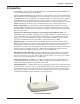
Chapter 1 - Introduction Introduction Congratulations on the purchase of the Multi-Tech System’s RouteFinder model RF802EW, one of the finest broadband routers available today. The RouteFinder RF802EW provides wireless users with seamless access to their existing wired LAN, enabling them to share broadband access to the Internet as well as other resources. Using the IEEE 802.
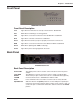
Chapter 1 - Introduction Front Panel RF802EW Front Panel Front Panel Description Link Lights when the LAN client is correctly connected to the 10/100 LAN. ACT Blinks when transmitting or receiving packets. LAN Lights when a successful connection to the 10/100 LAN is established. WLS Lights when a wireless connection is established. Serial Lights when the Serial async port is properly connected to a remote site. WAN Lights when a successful connection to the 10Base-T WAN is established.
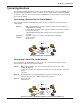
Chapter 1 - Introduction Typical Applications The following examples provide information about typical applications using the RF802EW. They describe using the RF802EW to connect a remote site via a cable modem, using the RF802EW to segment a local area network, and using the RF802EW to connect a LAN to the Internet using one shared IP address. Connecting a Remote Site via Cable Modem In the following example the RF802EW is used to connect a LAN to the Internet via DSL or a cable modem.
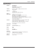
Chapter 1 - Introduction Specifications Hardware ARM RISC CPU 32 bit, 40MHZ 4MB DRAM and 512k Flash ROM UART Serial port controller LAN Port Interface: 1 10Base-T/100BaseTX RJ-45 Connection Standard: 802.3 WAN Ports 1 x 10Base-T 1 x RS232 (V.24) DTE Speed: Up to 230K asynchronous Wireless Access Point Protocols IEEE 802.11b for wireless LAN Date Rates: 11, 5.5, 2, 1 Mbps data rate per channel RF Frequency: 2.4-.
Chapter 2 - Hardware Installation
Chapter 2 - Hardware Installation Hardware Installation Safety 1. Never install telephone wiring during a lightning storm. 2. Never install telephone jacks in a wet location unless the jack is specifically designed for wet locations. 3. This product is to be used with UL and cUL listed computers. 4. Never touch uninsulated telephone wires or terminals unless the telephone line has been disconnected at the network interface. 5. Avoid using a telephone (other than a cordless type) during an electrical storm.
Chapter 2 - Hardware Installation Cabling Cabling your RouteFinder requires making the appropriate connections to PCs, Cable, or DSL modem, analog modem or ISDN TA (optional), AC power and the router. Because this device also acts as a DHCP server, after your device is properly cabled, you will need to follow the configuration instructions provided in the Software Installation and Configuration chapter.
Chapter 3 - Software Installation and Configuration
Chapter 3 - Software Installation and Configuration Software Installation and Configuration Before beginning the installation process, ensure that your system meets all hardware and software requirements: • Intel 486 or higher processor. • 10/100 Base-T cable to connect the RF802EW to the network. • One DSL or Cable Modem. • A networked computer with Windows 95/98/2000, Windows NT 3.
Chapter 3 - Software Installation and Configuration Using RouteFinder Setup Wizard Note: Before beginning this procedure, ensure that your RF802EW is properly connected to the network and that the power is turned on. After installing the software, you may return to the RouteFinder Setup Wizard at any time, by clicking Start | Programs | RouteFinder Manager | RouteFinder Wizard. Before running the Setup Wizard, it is strongly recommended that you exit all Windows programs. 1.
Chapter 3 - Software Installation and Configuration Record the values presented in the Device Information panel for later reference. Device IP Address ______________________ Device MAC Address ____________________ Device Firmware Version _________________ Click Next. Note: If a message appears indicating the device is not found, or you do not see the device you are attempting to configure listed, click Refresh Device List. 6. The Setup Wizard: Device IP Address dialog box displays.
Chapter 3 - Software Installation and Configuration function only, or Enable Wireless Access Point + Router function. If you are using NAT Enabled, you may also select Enable PPPoE. • Select Enable Wireless Access Point function only to set AP’s IP manually or acquire an IP address from a DCHP server. • Select IP Routing (NAT Disabled) to allow the RF802EW to function as a router between the IP segment of the server and another IP segment.
Chapter 3 - Software Installation and Configuration Select Enable PPPoE to use the RF802EW with a time-base, rather than fixed-cost DSL modem connection. Enter the User Name and Password provided by your ISP. This option is most often used when connecting via DSL to the Internet. Note: Enable PPPoE is valid only when IP Routing (NAT Enabled) is selected. Click Next. 10. The External IP Assignment dialog box displays.
Chapter 3 - Software Installation and Configuration • Select IP Routing (NAT Enabled) to allow all users in the two IP segments (LAN and WAN Ethernet) to share one IP address to the Internet. You may also select this option to use the serial async port for dial backup in the event the DSL or cable modem becomes unavailable. • Select IP Routing (NAT Disabled) to connect other IP segments through the serial async port. See the IP Routing instructions continue on page 26.
Chapter 3 - Software Installation and Configuration • Variable Callback: Select Variable Callback for remote users that travel or dial-in from various locations and need callback security. This option allows clients to specify the callback telephone number each time they connect to the network. Click Add after entering information for each Local Client. Click Next and continue with Step 10 when all users have been added to the database.
Chapter 3 - Software Installation and Configuration IP Routing (NAT Enabled) and IP Routing (NAT Disabled) If you select IP Routing for the asynchronous port, the Setup Wizard: IP Routing dialog box displays. Enter the information required to dial-up and login to your ISP’s remote server: Telephone Number Enter the phone number used to dial your remote server (ISP).
Chapter 3 - Software Installation and Configuration 11. The Setup Wizard: Modem Settings dialog box displays. The final step in configuring your RF802EW for basic operations is to define your modem Manufacturer, Model and the DTE baudrate or speed of communication between the RF802EW’s serial async port and your modem or ISDN TA. Select your modem and baudrate as described on the following pages.
Chapter 3 - Software Installation and Configuration 15. The Check List dialog box displays summarizing your configuration selections. Ensure that all values have been correctly entered. If you find an incorrect setting, click Back to return to the screen containing the error and correct it. When complete, click Next to return to the Check List dialog box. Click Finish to complete the configuration. 16. The Note dialog box displays indicating that you have completed the Setup Wizard.
Chapter 4 - Telnet
Chapter 4 - Telnet Using Telnet to Configure your RouteFinder Telnet is a telecommunications software utility which allows you to access a remote device. The RouteFinder RF802EW has a built-in Telnet Server that enables a Telnet client to remotely configure the device using a menu system.
Chapter 4 - Telnet Router IP Address Enter the IP address assigned to the RF802EW on your local network. The new address will take effect after you have selected Save and Restart Server. Router Subnet Mask Enter the subnet mask for your local network. Router Name Enter a network name for the RF802EW. If your ISP requires your device to have a name, you may use the value entered in this field. Router Password The default is no password.
Chapter 4 - Telnet Async Port Settings The async port may be used for IP Routing or Remote access. For more information, see the Async Port section of the RouteFinder Manager chapter. IP Routing If you will use the async port for IP Routing, enter the following information as described: Telephone number Enter the phone number the async device must dial to connect to the remote system. User Name Enter the User Name that will be used for authentication on the remote system.
Chapter 4 - Telnet Assign Remote IP Select Enable or Disable. If you select Enable, you will be prompted to enter an address to be assigned to the remote system. Remote Access To configure the async port for Remote Access, enter values for each of the following: Remote Access Port Settings IP Assigned Method Select the method the client will use to have their IP address assigned. Protocols Default value is Both IP and IPX enabled.
Chapter 4 - Telnet RADIUS Server Select Enable to configure remote users to authenticate on a RADIUS Server. RADIUS Access Server IP Enter the IP address of the RADIUS Access server. RADIUS Accounting Server IP Enter the IP address of the RADIUS Accounting server. In most configurations, the Access and Accounting server are located on the same machine, so the IP address is the same for both. RADIUS Secret Enter the secret code or password for the RADIUS Server.
Chapter 4 - Telnet Diagnostic The Diagnostic option performs basic testing of the RouteFinder, displays information about your firmware and offers options for assigning the LAN and WAN MAC addresses as may be required by your ISP. Type any key to return to the main menu.
Chapter 5 - RouteFinder Manager
Chapter 5 - RouteFinder Manager RouteFinder Manager RouteFinder manager is the main program used to configure all the settings of your RF802EW. 1. To run RouteFinder Manager, double-click the RouteFinder Manager icon on your desktop, or click Start | Programs | RouteFinder Manager | RouteFinder Manager. 2. The Manager dialog box displays. 3. The RF802EW automatically searches your network for devices available for configuration and displays them in the Available Devices list box.
Chapter 5 - RouteFinder Manager General Settings After selecting your device from the Available Devices list, click General Settings to view or change all of the major network settings for the RF802EW including LAN and WAN Ethernet segment settings, DNS information, IP Routing, and Remote Access settings. Most of the settings here were entered in Setup Wizard. However, some important settings can be entered only in RouteFinder Manager.
Chapter 5 - RouteFinder Manager LAN Ethernet Segment Server IP address This IP address is the internal LAN IP address of the RF802EW. The address entered into the Setup Wizard is displayed here (for example, 192.168.2.1). Server IP Netmask The RF802EW subnet mask generally can be left at the default value of 255.255.255.0. WAN Ethernet Segment Select NAT (Network Address Translation) to provide firewall protection and enable all local LAN users to share one IP address to access the Internet.
Chapter 5 - RouteFinder Manager 3. The IP Routing Settings dialog box displays. IP Routing (NAT Enabled) If NAT is enabled, all local users will be firewall protected and will share one IP address through the Async port. Enter values in the fields as described: Tel Number Enter the phone number required to access your ISP. User Name Enter the account user name to be authenticated by your ISP. Password Enter the user account password to be authenticated by your ISP.
Chapter 5 - RouteFinder Manager Allow Remote Dial-In This option allows a remote site to dial-in to this network. 1. From the IP Routing Settings dialog box, select Allow Remote Dial-In. 2. Click Remote Authentication Settings. 3. The Remote Connection Authentication dialog box displays. 4. You must select one of three methods to define the authentication protocol to be used when a remote site is dialing in to your site. You may select: • None - No authentication needed.
Chapter 5 - RouteFinder Manager Remote Connection Authentication Settings When you select Allow Remote Dial-in, you must determine the method that remote users must use to be authenticated on your system. If you choose the PAP or CHAP authentication protocol, you must select Use Local Settings, Use Local Client List or Use RADIUS Server authentication. Use Local Setting You may create a Remote User Name and Remote Password to log in to the system.
Chapter 5 - RouteFinder Manager Assign a specific IP address for this user Select this option if you would like to have a specific IP address assigned to this user. Enter the IP address. This IP address will be used each time the client logs in and will override the Assign Remote Site an IP Address option as shown in the IP Router Setting dialog box. Click Add to add this client to the Local Client List.
Chapter 5 - RouteFinder Manager Remote Access Settings 1. From the General Settings dialog box, select the Remote Access option and click Remote Access Settings. 2. The Remote Access Settings dialog box displays. Enter the following: IP Assigned Method for Remote Clients A remote client must have an IP address to connect to the network. IP addresses may be assigned automatically from a designated IP address pool using DHCP, or the IP address may be manually assigned.
Chapter 5 - RouteFinder Manager Enable IP Mapping - Virtual Server IP Mapping is available only when NAT is enabled. If NAT is enabled for a particular port, that port is firewall protected. The Enable IP Mapping function allows you to open a “hole” in your firewall to allow access to your LAN via the Internet. For example, you can use the IP mapping function to access an FTP server on your LAN via the Internet. IP Mapping is most suitable to fixed or static IP addressing. 1.
Chapter 5 - RouteFinder Manager Port Settings The Modem Settings options are used to configure the communication between your modem or ISDN TA and your RouteFinder serial port. You must specify the baudrate, modem and modem string settings for your device. 1. To view or change the port settings, from the main Manager dialog box, click Port Settings. The Port Settings dialog box displays. 2. Complete the following: Baudrate Use the list to select the Remote Access DTE speed for your device.
Chapter 5 - RouteFinder Manager Edit Login Script for Remote Access 1. From the Port Settings, click Edit Login Script. 2. The login Script dialog box displays. A sample remote access login script is shown below. If a remote access client is configured to “bring up a terminal window after dialing”, this remote access login script initiates. For Remote Access, the device will act as the server side... Send ‘Welcome’ displays “Welcome” to remote site.
Chapter 5 - RouteFinder Manager Wait ‘CONNECT’ Wait ‘CONNECT 6’ Other Go Jump4 Hangup login script. The Modem will wait for CONNECT to display before moving to the next command. Modem will wait for “CONNECT” to display before moving to the next command. If CONNECT does not display, the modem will go to line 6 of the login script. FUNCTION Begins PPP Goes back to line 4 of the login script. Hangs up the modem.
Chapter 5 - RouteFinder Manager 12 13 14 15 Hangup Send ‘AT S0=1’ Send ‘ATDT 8885678’ Wait ‘Connect’ 23 16 Wait ‘username:’ 23 17 18 19 20 21 22 23 24 Send ‘Stephen’ Wait ‘password:’ SH ‘5678’ Wait‘====>‘ Send‘1‘ Go Hangup Jump 2 Hangs up Modem Sends initial string ‘AT SO=1’ to modem Dials phone number 888-5678 (ISP #2) Waits for ISP to send reply ‘CONNECT’. If no CONNECT, goes to line 23. Waits for ISP to send reply ‘username’. If no response, goes to line 23.
Chapter 5 - RouteFinder Manager Individual Port Options Individual Port Options lets you set the idle-timeout function for each serial port of the RouteFinder. You can set the number of minutes you wish to allow a connection to stay idle before disconnection. Note: Default idle timeout for IP Routing is 5 minutes. Default idle timeout for Remote Access is 30 minutes.
Chapter 5 - RouteFinder Manager IP Address Pool The IP Address Pool contains the range of IP addresses that will be automatically assigned to the clients of your network as they connect to the network. Note: By default, the IP address pool range is from 100 to 200. Ranges are listed in the IP Address Pool table. To change the range: 1. Select the existing range of addresses. 2. Enter a new range. 3. Press Insert. To delete an IP Address range: 1. Select the range of addresses. 2. Press Delete.
Chapter 5 - RouteFinder Manager Routing Settings Routing is the process of moving a packet of data from source to destination. The RF802EW acts as a router to enable messages to pass from one computer to another and eventually reach the target machine. Part of this process involves analyzing a routing table to determine the best path. Use the information below to create a routing table to connect your network to another network, or to connect subnets within your network.
Chapter 5 - RouteFinder Manager Routing Table The routing table stores the routing information so that the RF802EW knows how to route the IP packets to the proper network. PC 1 192.168.3.9 WAN Ethernet 192.168.3.1 RF802EW-1 LAN Ethernet 192.168.5.1 WAN Ethernet 192.168.5.254 RF802EW-2 LAN Ethernet 172.168.2.254 PC 2 172.168.2.1 What is the purpose of the routing table? In the diagram above, the RF802EW-1 has the routing information to route between 192.168.3.x and 192.168.5.x.
Chapter 5 - RouteFinder Manager Filter Settings You can use Filter Settings to choose which packets are allowed to enter the network and which packets will be blocked. Filter Settings can be used to filter network services such as Mail, WWW, FTP, Telnet and News. 1. From the main Manager dialog box, select your RF802EW, then Filter Settings. 2. The Filter Settings dialog box displays. 3. Select the Block tab or the Pass tab to define your filtering.
Chapter 5 - RouteFinder Manager Note: Level one is the highest level, level sixteen is the lowest privilege level. Example: Let’s say you configure a filter rule for IP address 192.168.100.72 with a privilege level of 16 to Pass using socket number 80. At the same time, you set the same filter rule to block IP Address 192.168.100.72 with a privilege level of one. The RF802EW will implement the filter to block the IP address 192.168.100.72 because the privilege level is higher.
Chapter 5 - RouteFinder Manager The filter works by filtering TCP/IP port numbers. The 5 most commonly used port numbers are listed for you. They include the port numbers for Mail, WWW, FTP, Telnet and News. If you would like to filter other services, you must know the port number for the service. 4. Click Edit to enter new service port numbers. 5. Enter the TCP/UDP Port Number and click Add. Note: Refer to the Glossary of the User Guide for a definition of Port. 6. Click Privileged Clients. 7.
Chapter 5 - RouteFinder Manager Wireless Settings Click Wireless Settings in the RouteFinder Manager menu to open the Wireless Settings dialog box. You can enter the ESSID and Channel number for your wireless router. All wireless workstations must use the same ESSID. You may need to try different channels to avoid interference. Encryption (WEP) The WEP is a data security measure. The RC4 algorithm encrypts the wireless portion of data transmissions.
Chapter 5 - RouteFinder Manager Refresh Device List 1. From the main Manager dialog box, click Refresh Device List to search the LAN for available network devices and display them in the Available Devices list. Note: If a device does not appear in the list, click Refresh Device List again to determine if the device will appear on the list. If the device still does not appear, ensure that all cables are correctly connected and that the power to the RF802EW is turned on.
Chapter 5 - RouteFinder Manager Note: Entering a password is strongly recommended to protect your RouteFinder from unauthorized reconfiguration. If you enter a password, ensure you have selected something that will be easy to remember or write it down and store it in a safe location. If you have completely forgotten your password, contact Multi-Tech Technical Support for assistance. Refer to Chapter 10 in this User Guide for more information about our Technical Support services. 2. Click OK.
Chapter 5 - RouteFinder Manager click then navigate to and select the file. 6. Click OK to load and apply the settings to the RouteFinder. Upgrade Firmware Warning: Upgrade the firmware of your RouteFinder RF802EW only under the advice and direction of the Multi-Tech Technical Support Group. Improperly upgrading the RF802EW may disable the device! The Upgrade Firmware options allow you to upgrade your RF802EW firmware.
Chapter 5 - RouteFinder Manager General Diagnostic The General Diagnostic option displays network device information and allows you to determine if the RF802EW is functioning properly. 1. From the main Manager dialog box, click General Diagnostic. 2. The General Diagnostic dialog box displays information about the RF802EW. 3. Record the information if necessary and click OK to exit.
Chapter 6 - RouteFinder Monitor
Chapter 6 - RouteFinder Monitor RouteFinder Monitor RouteFinder Monitor is a utility that provides both monitoring and troubleshooting functions. Running RouteFinder Monitor 1. Click on the RouteFinder Monitor icon, or select Start | Programs | RouteFinder Manager | RouteFinder Monitor. 2. The RouteFinder Monitor dialog box displays. Note: If you receive a message stating “Device is not found”, refer to the Troubleshooting chapter in this User Guide.
Chapter 6 - RouteFinder Monitor 4. The monitor display window displays the actions of the test. 5. To terminate the connection, refer to the Terminate Connection instructions which follow. 6. Click Exit to close the Test Connection dialog box. Terminate Connection The Terminate Connection option is designed to allow the Network Administrator to terminate an RF802EW connection instantly. 1. From the main RouteFinder Monitor dialog box, select Terminate Connection. 2.
Chapter 6 - RouteFinder Monitor Save Now If you want to save the monitor display at any point in time, select the monitor you want to save to a file (TCP/IP, Event Message). Select the File Name and File Directory to which you’d like to save the file and click Save. Autosave If you wish to automatically save the information displayed on the monitor to a database file, enable the AutoSave function.
Chapter 6 - RouteFinder Monitor 3. Enter each computer’s IP Address and associated User Name in the provided fields. 4. Click Add after each IP address and name have been added to the list. 5. When all addresses have been added, click OK. Event Messages Event Messages are displayed in the lower half of the RouteFinder Monitor display. Event Messages provide information about the communication occurring between your network device, ISDN TA/modem and the remote server (ISP).
Chapter 6 - RouteFinder Monitor Time Tab The Time Tab provides information about the amount of time the device has been powered on, the total connection time, the current connection time and the amount of data transferred and received. 1. From the main RouteFinder Monitor dialog box, click the Time tab. 2. The Time tab displays information for each port. Device Power Turned On Displays the time and date that your RF802EW was powered on.
Chapter 6 - RouteFinder Monitor Status Tab The Status tab provides information about the status of the WAN Ethernet and Async ports. 1. From the RouteFinder Monitor dialog box, click the Status tab. 2. The Status tab information displays: WAN Ethernet This indicator light shows that either the IP Routing or the Remote Access function is in use. Async Port Modem Power The indicator light is lit when the modem power is turned on.
Chapter 5 - RouteFinder Manager Statistics Tab The Statistics tab indicates, by port, how many bytes of data have come in and out through the RouteFinder.. 1. From the RouteFinder Monitor dialog box, click the Statistics tab. 2. The Statistics tab dialog box displays. 3. You may view the following information: IP Address The IP address of the network device. Name The Name as entered in the IP/Address name option of the Main RouteFinder Monitor dialog box.
Chapter 7 - LAN Client Settings
Chapter 7 - LAN Client Settings LAN Client Settings In order for a computer to access the Internet, the TCP/IP protocol must be installed on the computer. Computers on your local LAN as well as computers dialing in to your network may use dynamic or static IP addresses. Dynamic IP addresses may be automatically assigned by the DHCP function of the RF802EW or another DHCP server. Static IP addresses can either be reserved from the DHCP server or manually configured on the individual workstation.
Chapter 7 - LAN Client Settings Adding the dial-up adapter (NT Server Connection): Windows 95/98: 1. Click Start | Settings | Control Panel. 2. Double-click the Network icon to open the Network dialog box. Win95 Win98 3. Click Add. The Select Network Component Type dialog box opens. 4. Select Adapter, then click Add. The Select Network adapters dialog box opens.
Chapter 7 - LAN Client Settings 5. In the Manufacturers list, select Microsoft. In the Network Adapters list select Dial-up adapter. 6. Click OK (twice) to return to, and then close, the Network dialog box. Windows NT: Dial-up Networking adds PPP and SLIP protocol support, enabling your workstation to gain access to a remote computer or network, even if your computer is not on a network. 1. Double-click My Computer, then double-click Dial-Up Networking. The following screen is displayed: 2.
Chapter 7 - LAN Client Settings Adding Client for Microsoft Networks (NT Server Connection): Windows 95/98: 1. In the Network dialog box, Configuration tab, click Add. 2. Select Network Client and click Add. 3. The Select Network Client dialog box displays. In the Manufacturer’s list, select Microsoft. In the Network Clients list, select Client for Microsoft Networks. 4. Click OK to add this Client and return to the Network dialog box.
Chapter 7 - LAN Client Settings Set Your Primary Network Logon (NT Server Connection): Windows 95/98: 1. In the Primary Network Logon list on the Configuration tab of the Network dialog box, select (the previously installed) Client for Microsoft Networks. 2. Click OK to close the Network dialog box. Set up Properties of Components (NT Server Connection): Dial-up Adapter Windows 95/98: 1. In the Network dialog box, Configuration tab, select the TCP/IP - Dial-up adapter. 2. Click Properties.
Chapter 7 - LAN Client Settings Network Client Windows 95/98: 1. In the Network dialog box, Configuration tab, select Client for Microsoft Networks. 2. Click Properties. The Client for Microsoft Networks Properties dialog box opens. 3. On the General tab, select the Log on to Windows NT domain check box. 4. Enter the name of your Windows NT domain, as provided by your Network Administrator in the Windows NT domain box. 5. Click OK to return to the Network dialog box. Identification Windows 95/98: 1.
Chapter 7 - LAN Client Settings Access Windows 95/98: 1. In the Network dialog box, click the Access Control tab. 2. Select Share-Level access control. 3. Click OK twice to return to, and then close, the Network dialog box. Note: You must restart your system for the new settings to take effect. Once your machine has restarted, you may continue the configuration process. Make Your New Connection (NT Server Connection): Windows 95/98: 1. Double-click My Computer. 2.
Chapter 7 - LAN Client Settings Dial in to your network (NT Server Connection): Windows 95/98: 1. You are ready to dial in to your network. 2. Double-click the new connection icon. The Connect To dialog box opens. 3. Enter the user name (if necessary) and password configured for you on the RF802EW. Note: If your particular situation permits, select the Save password check box. 4. Click Connect. 5.
Chapter 7 - LAN Client Settings 3. Click Add. The Select Network Component Type dialog box opens. 4. Select Adapter, then click Add. The Select Network adapters dialog box opens. Win95/98 5. In the Manufacturers list, select Microsoft. In the Network Adapters list select Dial-up adapter. 6. Click OK twice to return to, and then close, the Network dialog box.
Chapter 7 - LAN Client Settings Adding IPX/SPX (Novell Server Connection): Windows 95/98: 1. In the Network dialog box, Configuration tab, click Add. The Select Network Component Type dialog box opens. 2. Select Protocol and click Add. The Select Network Protocol dialog box opens. 3. In the Manufacturers list, select Microsoft. In the Network Protocols list, select IPX/SPXcompatible Protocol. 4. Click OK twice to return to, and then close, the Network dialog box.
Chapter 7 - LAN Client Settings Adding Client for NetWare Networks (Novell Server Connection): Windows 95/98: 1. In the Network dialog box, Configuration tab, click Add. 2. Select Network Client and click Add. 3. The Select Network Client dialog box displays. In the Manufacturer’s list, select Microsoft. In the Network Clients list, select Client for NetWare Networks. 4. Click OK to add this Client and return to the Network dialog box.
Chapter 7 - LAN Client Settings 7. Click Properties. 8. On the General tab, in the Preferred server box, enter the name of your Novell Server Domain. If necessary, select the First Network Drive, then verify that the Enable logon script processing check box is selected. (It’s the default.) 9. Click OK to return to the Network dialog box. Set Your Primary Network Logon Windows 95/98: 1. In the Network dialog box, Configuration tab, select Client for NetWare Networks as the Primary Network Logon. 2.
Chapter 7 - LAN Client Settings Set Your Access Control (Novell Server Connection) Windows 95/98: 1. In the Network dialog box, select the Access Control tab. 2. In the Control Access to shared resources using list, select Share-Level Access Control. Note: You must restart your system for the new settings to take effect. Make Your New Connection (Novell Server Connection) Windows 95/98: 1. Double-click My Computer. 2. Double-click the Dial-Up Networking folder. 3.
Chapter 7 - LAN Client Settings Accessing a Windows NT Server and a Novell NetWare Server Note: Before configuring your remote site, ensure TCP/IP has been installed on your NT Server. Perform the following procedures if your PC workstation needs to access both a Windows NT Server and a Novel NetWare Server. Adding the dial-up adapter (Novell/NT Server Connection): Windows 95/98/NT: 1. Click Start | Settings | Control Panel. 2. Double-click the Network icon to open the Network dialog box. Win95 Win98 3.
Chapter 7 - LAN Client Settings 4. Select Adapter, then click Add. The Select Network adapters dialog box opens. Win95/98 WinNT 5. (Win95/98 only) In the Manufacturers list, select Microsoft. In the Network Adapters list select Dial-up adapter. Note: In Windows NT workstation there is no Manufacturers list. 6. Click OK twice to return to, and then close, the Network dialog box. Adding TCP/IP (Novell/NT Server Connection): Windows 95/98/NT: 1. In the Network dialog box, Configuration tab, click Add. 2.
Chapter 7 - LAN Client Settings Adding Client for Microsoft Networks (Novell/NT Server Connection): Windows 95/98: 1. In the Network dialog box, Configuration tab, click Add. 2. Select Network Client and click Add. 3. The Select Network Client dialog box displays. In the Manufacturer’s list, select Microsoft. In the Network Clients list, select Client for Microsoft Networks. 4. Click OK to add this Client and return to the Network dialog box.
Chapter 7 - LAN Client Settings Adding IPX/SPX (Novell/NT Server Connection) Windows 95/98: 1. In the Network dialog box, Configuration tab, click Add. The Select Network Component Type dialog box opens. 2. Select Protocol and click Add. The Select Network Protocol dialog box opens. 3. In the Manufacturers list, select Microsoft. In the Network Protocols list, select IPX/SPXcompatible Protocol. 4. Click OK twice to return to, and then close, the Network dialog box.
Chapter 7 - LAN Client Settings Adding Client for NetWare Networks (Novell/NT Server Connection) Windows 95/98: 1. In the Network dialog box, Configuration tab, click Add. 2. Select Network Client and click Add. 3. The Select Network Client dialog box displays. In the Manufacturer’s list, select Microsoft. In the Network Clients list, select Client for NetWare Networks. 4. Click OK to add this Client and return to the Network dialog box.
Chapter 7 - LAN Client Settings Set Up Properties of Components (Novell/NT Server Connection): Dial-up Adapter Windows 95/98 1. In the Network dialog box, Configuration tab, select the TCP/IP - Dial-up adapter. 2. Click Properties. The TCP/IP Properties dialog box opens with the IP Address tab selected. 3. Ensure that Obtain an IP Address Automatically is selected. (It’s the default.) 4. Click OK to close the TCP/IP Properties dialog box. Network Client Windows 95/98: 1.
Chapter 7 - LAN Client Settings 7. Click Properties. 8. On the General tab, in the Preferred server box, enter the name of your Novell Server Domain. Select the First Network Drive and Enable Logon Script processing. 9. Click OK. Network Protocol Windows 95/98: 1. In the Network dialog box, Configuration tab, select IPX/SPX Compatible Protocol. 2. Click Properties. 3. Disable Client for Microsoft Networks and File and Printer Sharing for Microsoft Networks.
Chapter 7 - LAN Client Settings 3. Enter a name and description for your computer. 4. Click OK. Set Your Access Control: Windows 95/98: 1. In the Network dialog box, select the Access Control tab. 2. Select the Share-Level access control option. 3. Click OK twice to return to, and then close, the Network dialog box. Note: You must restart your system for the new settings to take effect. Once your machine has restarted, you may continue the configuration process.
Chapter 7 - LAN Client Settings Set Dial-up type (NT/Novell Server Connection) Windows 95/98: 1. Right-click the newly created connection icon, then click Properties; the My Connection dialog box opens. 2. On the General tab, click Server Type. The Server Types dialog box opens. Select PPP: Windows 95, Windows NT 3.5, Internet. 3. Select only the Log on to network, Enable software compression, and TCP/IP check boxes. Note: do not disturb any other items that are already checked.
Chapter 7 - LAN Client Settings 3. Click Add. The Select Network Component Type dialog box opens. 4. Select Adapter, then click Add. The Select Network adapters dialog box opens. Win95/98 5. In the Manufacturers list, select Microsoft. In the Network Adapters list, select Dial-up adapter. 6. Click OK twice to return to, and then close, the Network dialog box.
Chapter 7 - LAN Client Settings Adding TCP/IP (Unix Server Connection) Windows 95/98/NT: 1. In the Network dialog box, Configuration tab, click Add. 2. Select Protocol and click Add. 3. The Select Network Protocol dialog box is displayed. In the Manufacturers list [Win95 only], select Microsoft. In the Network Protocols list, select TCP/IP [Win95/98] or TCP/IP Protocol [WinNT only]. [Note: Windows NT workstation has no Manufacturers list.] Win95/98 4.
Chapter 7 - LAN Client Settings Make Your New Connection (Unix Server Connection) Windows 95/98: 1. Double-click My Computer. 2. Double-click the Dial-Up Networking folder. 3. Double-click Make New Connection (or Add New Connection, Win98). 4. Follow the on-screen instructions to configure your connection. Windows NT: 1. Double-click My Computer. 2. Double-click Dial-Up Networking. 3. When the Dial-Up Networking dialog box opens, click Install. 4.
Chapter 7 - LAN Client Settings Make New Connection (Windows 2000 only) Perform the following procedures to prepare your Windows 2000 PC workstation to access any of the remote Servers and enable applications such as e-mail, Web browsing, file sharing, and printing. 1. Double-click My Computer. 2. Double-click the Network and Dial-up Connections folder. 3. Double-click Make New Connection. 4. Click Next, then follow the on-screen instructions to configure your connection.
Chapter 8 LAN-to-LAN Settings
Chapter 8 - LAN-to-LAN Settings LAN-to-LAN Settings Setting up LAN-to-LAN Routing The majority of settings for LAN-to-LAN Routing are set up through RouteFinder Wizard or RouteFinder Manager when IP routing (NAT disabled) is configured. This section provides an overview of LAN -to- LAN Routing and shows you some of the benefits and limitations of LAN-toLAN Routing.
Chapter 7 - LAN Client Settings Note: If the computer you are attempting to access is on a remote LAN, you may need to press Find Now more than once while you wait for your network device to establish a dial-up connection to your remote LAN. Using LMHosts Important: Each computer on the LAN must have a copy of this lookup table. Once you have mapped the necessary computer or host names and IP addresses in the LMHosts file, copy this file to the appropriate folder on each computer on the LAN.
Chapter 9 - Troubleshooting
Chapter 9 - Troubleshooting Troubleshooting This chapter provides a list of common problems encountered while installing, configuring or administering the RF802EW. In the event you are unable to resolve your problem, refer to the Service, Warranty and Technical Support chapter of this User Guide for information about contacting our Technical Support representatives.
Chapter 9 - Troubleshooting Problem #3 The RouteFinder is connected to the Cable/DSL, but has problems accessing the Internet. • Ensure the workstation has TCP/IP properly configured. • Attempt to ping the IP address of the RF802EW. • Use RouteFinder Monitor to see if the WAN Ethernet port has successfully acquired a dynamic IP address from the ISP, or if the static IP address is valid.
Chapter 9 - Troubleshooting • If the scenario described above does not fit your situation, use RouteFinder monitor to view all events that are taking place between the modem and your ISP as you attempt to make a connection (a busy signal). Problem #8 After installing my RF802EW, my modem connection seems to be slower. • The RouteFinder device should have no effect on the modem speed. However, if more than one client is using the same modem through the RouteFinder, the speed will be reduced.
Chapter 10 - Service, Warranty and Technical Support
Chapter 10 - Service, Warranty and Technical Support Introduction This chapter begins with the terms of your RouteFinder’s warranty. In the Software User License Agreement section, you will find details about your software license agreement with Multi-Tech Systems. The Technical Support section offers information about on-line registration as well as phone numbers for contacting our Technical Support group.
Chapter 10 - Service, Warranty and Technical Support abuse, or user-caused damages are billed on a time-plus-materials basis. Addendum for International Products Distributors should contact Amex, Inc., for information about the repairs for your Multi-Tech product. Amex, Inc. 2724 Summer Street NE Minneapolis, MN 55413 U.S.A. Tel: +(612) 331-3251 Fax: +(612) 331-3180 Please direct your questions regarding technical matters, product configuration, verification that the product is defective, etc.
Chapter 10 - Service, Warranty and Technical Support Software User License Agreement IMPORTANT - READ BEFORE OPENING THE SOFTWARE PACKAGE This license agreement is a legal agreement between you (either an individual or a single entity) and Multi-Tech Systems, Inc. for the Multi-Tech software product enclosed, which includes computer software and may include associated media, printed materials, and “online” or electronic documentation (“SOFTWARE PRODUCT”).
Chapter 10 - Service, Warranty and Technical Support 4. WARRANTY. MTS warrants that the software will perform substantially in accordance to the product specifications in effect at the time of receipt by Customer. If it fails to perform accordingly, MTS will optionally repair any defect, or replace it. This warranty is void if the failure has resulted from accident, abuse, or misapplication. A signed Software Registration Card must be on file at MTS for this warranty to be in effect.
Chapter 10 - Service, Warranty and Technical Support Technical Support Multi-Tech provides free technical support for as long as your product remains in service. Before calling Technical Support, please read through the Troubleshooting chapter of this User Guide. Also, ensure you have completed the Recording RouteFinder Information section below.
Chapter 10 - Service, Warranty and Technical Support About the Internet Multi-Tech System’s is a commercial provider on the Internet. The Multi-Tech web site is located at http://www.multitech.com The Multi-Tech FTP site is located at ftp://ftp.multitech.com Ordering Accessories SupplyNet, Inc. can provide you with replacement transformers, cables and connectors for select Multi-Tech products. You can place an order with SupplyNet via mail, phone, fax or the Internet at: Mail: SupplyNet, Inc.
Appendixes
Appendixes Appendix A - Regulatory Compliance Information Class B Statement FCC Part 15 This equipment has been tested and found to comply with the limits for a Class B digital device, pursuant to Part 15 of the FCC Rules. These limits are designed to provide reasonable protection against harmful interference in a residential installation.
Appendixes Appendix B - Tools for your RF802EW RouteFinder Monitor If you are having problems, the RouteFinder Monitor can be a valuable tool to assist in troubleshooting. Additional troubleshooting information is available through the on-line help screens. Refer to Chapter 6 for more information about using the RouteFinder monitor. PING Ping is an acronym for Packet Internet Groper.
Appendixes TRACERT TRACERT is an extensive PING utility that allows you to trace the route of an IP address. The utility reports the number of router hops, the time for each hop, and any failed attempts to cross a hop. The information provided by this utility assists you to locate the specific site of a failed PING. You can run TRACERT at the DOS prompt (e.g., c:\tracert www.yahoo.com).
Appendixes Appendix C - Cabling Diagrams WAN/LAN Cables LAN WAN Pin Circuit Signal Name 1 TD+ Data Transmit Positive 2 TD- Data Transmit Negative 3 RD+ Data Receive Positive 6 RD- Data Receive Negative Serial Cable To RF802EW Male 8-pin Mini-DIN Male DB-25 1 8 2 3 3 2 4 20 5 7 6 6 7 4 8 5 To Modem Transmit Data Gnd Receive Data 111
Glossary
Glossary The following is a glossary of terms used in this manual: B Baudrate Baudrate refers to the number of bits per second (Bps) that are transmitted between your network device and modem or ISDN TA. D DHCP (Dynamic Host Configuration Protocol) A protocol that was made to lessen the administrative burden of having to manually configure TCP/IP Hosts on a network.
Glossary IP Addresses A computer on the Internet is identified by an IP Address. A computer’s IP address is like a telephone number. It identifies one address or in this case one computing device. Every computer or device on the network must have a different IP address. An IP address consists of four groups of numbers called octets, which are separated by periods. For example, 213 .0.0.1 is an IP address. An IP address consists of a network portion and a host portion.
Glossary that requested it. If someone on the Internet tries to access your network, the firewall function of the RouteFinder stops the request. The device will not reverse translate network addresses unless you have specifically allowed this feature using the Virtual Server function (IP Mapping). NetworkAddress The network portion of an IP address. For a class A network, the network address is the first byte of the IP address.
Glossary T TCP/IP (Transmission Control Protocol/Internet Protocol) A suite of communication protocols used to connect hosts on the Internet. Every computer that wants to communicate with another computer on the Internet must use the TCP/IP protocol to transmit and route data packets. The format of an IP address is a 32-bit numeric address written as four octets separated by periods. Each number can be zero to 255.
Index I Index A Adding TCP/IP ......................................... 69, Async Port ...................................................... Authentication ................................................ Available Devices ........................................... 90 35 38 33 B Back Panel ....................................................... 8 Baudrate ......................................................... 42 C Cabling ...........................................................
Index Rx ................................................................... 65 S Safety ............................................................. 12 Save Settings to File ...................................... 55 Save to File .................................................... 60 SMTP ............................................................. 41 Software Installation ....................................... 15 Software User License Agreement ............... 103 Statistics Tab ......................