
User manual


RZ 086 - index a
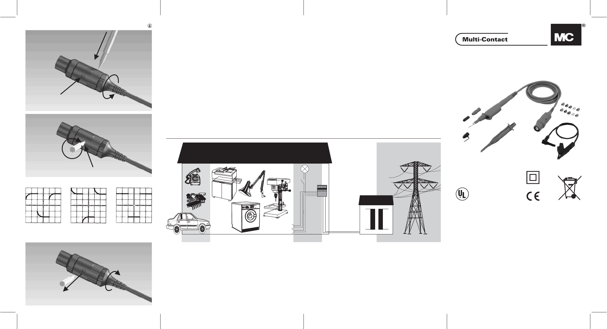
3
5
4
1
2
2a
3a
Kompensation / Compensation
Abb. / fig. / ill.
Unterkompensiert
Under compensated
Sous-compensé
Überkompensiert
Over compensated
Sur-compensé
Abgeglichenes Rechteck
Correctly compensated
Compensé exactement
A
RZ 086
LISTED
Control Nr.: 95D1
Test Accessories
n
Benutzerinformation
n
User Information
n
Information pour l’utilisateur
www.multi-contact.com
Isoprobe
®
III - 10:1 ECO
Kompensation (siehe Abb.
¯
)
1. Schutzhülse entriegeln.
2. Schutzhülse drehen bis die Einstell
-
schraube (2a) durch die Öffnung zugänglich
ist.
3. Kompensation mit einem Abgleichstift
(Schlitzbreite max. 2,5 mm) einstellen (3a).
+
Für eine unverfälschte Wiedergabe des
Messsignals sind die Kapazitäten von Tast
-
teiler und Oszilloskop-Eingang aufeinander
abzustimmen. Dazu besitzt der Tastkopf
eine Einstellschraube. Zur Kalibrierung
schließen Sie den Tastkopf an das Oszillo
-
skop an und greifen mit der Spitze das Re
-
ferenzsignal des Oszilloskops ab. Drehen
Sie die Einstellschraube so lange, bis das
Oszilloskop die Rechteckform des Signals
zeigt.
4. Abgleichstift herausziehen.
5. Schutzhülse drehen bis sie einrastet.
Compensation (see ill.
¯
)
1. Unlock the protective sleeve.
2. Turn the protective sleeve until the adjust
-
ment screw (2a) is accessible through the
opening.
3. Adjust the compensation with an adjust
-
ment pin (Slot width max. 2.5 mm) (3a).
+
For an accurate indication of the measuring
signal, it is necessary to adjust the capacity
of the probe to the input capacity of the os
-
cilloscope. For this purpose the probe has
an adjustment screw. Connect the probe to
the oscilloscope and the tip to the reference
calibration signal of the oscilloscope. Turn
the adjustment screw until the oscilloscope
shows an exact square wave.
4. Pull out the adjustment pin.
5. Turn the protective sleeve until it en
-
gages.
Compensation (voir fig.
¯
)
1. Déverrouiller le fourreau de protection.
2. Tourner le fourreau de protection jusqu’à
ce que la vis de compensation (2a) soit ac
-
cessible.
3. Procéder au calibrage avec un outil de
réglage (largeur de fente max. 2,5 mm) (3a).
+
Pour une mesure exacte, il faut adapter les
capacités de la sonde et de l’oscilloscope. A
cette fin, la sonde est équipée d’une vis de
compensation. Pour la calibration, connec
-
ter la sonde à l’oscilloscope et la pointe au
signal de référence de l’oscilloscope. Tour
-
nez la vis de calibration jusqu’à ce qu’un si
-
gnal parfaitement rectangulaire apparaisse
sur l’oscilloscope.
4. Retirer l’outil de réglage.
5. Tourner le fourreau en position ver
-
rouillée.
CAT II
CAT I
CAT IV
T
imer
S
e
t
C
lean
F
i
l
t
e
r
Hea
t
s
etting
Cot
t
o
n
Sy
n
the
t
i
cs
A
cryli
c
s
25-35 40-5
5
6
0-75 85-
10
0
25-
35 40-7
5
60-
75 "
50
-
80 70-1
00
""
DRYINGSETTINGS
1kg
2k
g
3
kg
5kg
Reverse
Dryer
CAT III
Messkategorien (siehe Abb.°)
(gemäß IEC / EN 61010-031 : 2002)
CAT I: Gilt für Messobjekte, die nicht mit der
Netzversorgung verbunden sind.
CAT II: Gilt für Messungen an Geräten, die mit
dem Netz verbunden sind oder aus dem Netz
versorgt werden, jedoch keinen Bestandteil der
Installation darstellen.
CAT III: Gilt für Messungen innerhalb der Haus-
oder Gebäudeinstallation.
CAT IV: Gilt für Messungen an der Quelle der
Installation.
Measurement Categories (see ill.°)
(according to EN 61010-031 : 2002)
CAT I: Applies to test objects that are not con
-
nected to the mains.
CAT II: Applies to measurements on equipment
that is connected to the mains or supplied from
the mains without constituting a part of the
mains installation.
CAT III: Applies to measurements inside the
house or building installation.
CAT IV: Applies to measurements at the supply
source of the installation.
Catégories de mesure (voir fig.°)
(selon EN 61010-031 : 2002)
CATI:Correspond aux mesures réalisées
sur des circuits non réliés directement à une
alimentation réseau.
CATII:La catégorie de mesure II correspond
aux mesures réalisées sur des appareils, direc
-
tement reliés au réseau ou alimentés par le ré
-
seau, mais qui ne font pas partie intégrante de
l’installation.
CAT III : La catégorie de mesure III correspond aux
mesures réalisées dans l'installation du bâtiment.
CATIV:La catégorie de mesure IV correspond
aux mesures réalisées à la source de l'installation.
RZ 086