DE Sicherheitshinweise 2-3 Zubehör und Werkzeug, Lieferumfang 4 - 5 Bauanleitung 6-9 Abbildungen 30 - 37 Ersatzteile 60 - 61 EN Safety information Accessories and tools, contents Assembly instructions Illustrations Spare parts 12 - 13 14 - 15 16 - 19 30 - 37 60 - 61 FR Conseils de sécurité Accessoires et outils, contenu Notice de montage Illustrations Pièces de rechanges 22 - 23 24 - 25 26 - 29 30 - 37 60 - 61 IT Istruzioni di sicurezza Accessori e utensili, ambito fornitura Istruzioni di montaggio
Sicherheitshinweise für MULTIPLEX-Flugmodelle DE Beim Betrieb des Modells sind alle Warn- und Sicherheitshinweise der Betriebsanleitung unbedingt zu beachten. Das Modell ist KEIN SPIELZEUG im üblichen Sinne. Benutzen Sie Ihr Modell mit Verstand und Vorsicht, und es wird Ihnen und Ihren Zuschauern viel Spaß bereiten, ohne eine Gefahr darzustellen. Wenn Sie Ihr Modell nicht verantwortungsbewusst betreiben, kann dies zu erheblichen Sachbeschädigungen und schwerwiegenden Verletzungen führen.
Sicherheitshinweise für MULTIPLEX-Flugmodelle chenden“ Folgeschäden bei späteren Flügen zu technischem und Materialversagen und Abstürzen führen. • Feuergefahr durch Fehlfunktion der Elektronik: Akkus sind sicher aufzubewahren. Sicherheitshinweise der Elektronikkomponenten im Modell, des Akkus und des Ladegeräts sind zu beachten. Elektronik ist vor Wasser zu schützen. Regler und Akkus müssen ausreichend gekühlt werden.
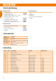
Zubehör und Werkzeug DE Benötigtes Zubehör Benötigtes Werkzeug • 1 x Zacki2 Elapor® 20g • 1x Antriebssatz EasyStar 3 mit Motor ROXXY BL Outrunner C28-30-1100kV und Regler ROXXY BL-Control 720 S-BEC • 4x Servo MS-12020 MG • 1x Empfänger RX-5 light M-LINK 2,4 GHz • 1x Akku ROXXY EVO LiPo 3 - 2200M 20C • Ladegerät 110-240V MULTIcharger L-703 EQU # 1-01291 # 1-01657 # 1-01654 # 55808 # 316655 # 82523 • • • • • Schere Klingenmesser Kombizange Dorn Ø 4-5 mm oder kleine Rundfeile Heißkleber Optionales Zube
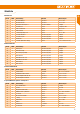
Stückliste Kleinteilesatz DE lfd. Nr Stück Bezeichnung Material Abmessungen 20 3 Klettband Pilzkopf Kunststoff 25 x 60 mm 21 3 Klettband Velours Kunststoff 25 x 60 mm 22 1 Ruderhornsatz EasyStar 3 Kunststoff / Metall Fertigteil 23 4 Kardanbolzen Metall Fertigteil Ø6 mm 24 4 Inbus-Gewindestift Metall M3 x 3 mm 25 1 Inbusschlüssel Metall SW 1,5 26 2 Querrudergestänge m.Z.
Bauanleitung DE Vor dem Bau 9. Verschlussklammern einkleben Prüfen Sie den Inhalt Ihres Baukastens. Dazu sind die Abb. 1, 2 + 3 und die Stückliste hilfreich. Kleben Sie die Verschlussklammern ㉗ in beide Rumpfhälften ein. Auch hier den Aktivator auf das Kunststoffteil sprühen und ablüften lassen. Abb. 12 1. Ablängen der Bowdenzugrohre Schneiden Sie mit einem scharfen Bastelmesser die Bowdenzugrohre (Ø 3 mm) gemäß Abb. 3 ab. Die Bowdenzugrohre (Ø 2 mm) werden fertig geliefert. 2.
Bauanleitung 15. Ruderhörner am Leitwerk anbringen Bestreichen Sie die Aussparungen der Schaumteile im Bereich der Aufdickungen mit Sekundenkleber. Platzieren Sie die Ruderhörner ㉒ und die Gegenplatten entsprechend der auf der Rückseite eingeprägten Nummer: Höhenruder -> Gegenplatte Seitenruder -> Gegenplatte Verschrauben Sie die Gegenplatten durch die Ruderhörner mit je zwei Schrauben . „Fädeln“ Sie den Steuerdraht der Seitenruderanlenkung in die Bohrung des Kardanbolzen ㉓ ein.
Bauanleitung DE 31. Luftschraube zusammenbauen Mit den zwei Zylinderstiften werden die beiden Luftschraubenblätter am Propellermitnehmer befestigt. Abb. 32 Schieben Sie den Spannkonus durch den Mitnehmer und setzten Sie den Zusammenbau in den Propellermitnehmer ein. Die U-Scheibe und die Zahnscheibe werden von der anderen Seite aufgeschoben. Schrauben Sie die M6-Mutter auf den Spannkonus .
Bauanleitung 38. Vorbereitungen für den Erstflug Für den Erstflug warten Sie einen möglichst windstillen Tag ab. Besonders günstig sind oft die Abendstunden. Wichtig: Vor dem ersten Flug unbedingt einen Reichweitentest durchführen! Halten Sie sich dabei an die Vorgaben des Herstellers Ihrer Fernsteuerung! Sender- und Flugakku sind frisch und vorschriftsmäßig geladen. Falls etwas unklar ist, sollte auf keinen Fall ein Start erfolgen.
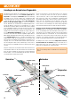
Grundlagen am Beispiel eines Flugmodells DE Ein Flugzeug (egal ob Modell oder „manntragend“) lässt sich mit den Rudern um folgende drei Achsen steuern: Hochachse, Querachse und Längsachse. Die Betätigung des Höhenruders ergibt eine Veränderung der Fluglage um die Querachse (Nicken). Bei Seitenruderausschlag dreht das Modell um die Hochachse (Gieren). Wird Querruder gesteuert, so dreht das Modell um die Längsachse (Rollen).
Grundlagen am Beispiel eines Flugmodells Das Tragflügelprofil Die EWD Die Tragfläche hat ein gewölbtes Profil an der die Luft im Flug vorbeiströmt. Die Luft oberhalb der Tragfläche legt gegenüber der Luft auf der Unterseite in gleicher Zeit eine größere Wegstrecke zurück. Dadurch entsteht auf der Oberseite der Tragfläche ein Unterdruck mit einer Kraft nach oben (Auftrieb) die das Flugzeug in der Luft hält. Abb.
Safety information for MULTIPLEX airplane models When operating the model, all warning and safety information in the operating instructions must be observed. EN The model is NOT A TOY in the conventional sense. If you use your model carefully, it will provide you and your spectators with lots of fun without posing any danger. If you do not operate your model responsibly, this may lead to significant property damage and severe injury.
Safety information for MULTIPLEX airplane models The electronics must be protected from water. The controller and the batteries must be sufficiently cooled. The instructions of our products may not be reproduced and/or published – not even in part – in print or electronic media without the express (written) permission of Multiplex Modellsport GmbH & Co. KG.
Accessories and tools Required accessories EN Required tool • 1 x Zacki2 Elapor® 20g • 1x power kit EasyStar 3 with motor ROXXY BL Outrunner C28-30-1100kV and controller, ROXXY BL-Control 720 S-BEC • 4x servo MS-12020 MG • 1x receiver RX-5 light M-LINK 2,4 GHz • 1x battery ROXXY EVO LiPo 3 - 2200M 20C • MULTIcharger L-703 EQU 110-240V # 1-01291 # 1-01657 # 1-01654 # 55808 # 316655 # 82523 • • • • • Scissors Balsa knife Combination pliers 4 - 5 mm Ø bradawl or small round file Hot glue Optional acces
List of parts Small parts set Serial no. Qty. Name Material Dimensions 20 3 Velcro tape, hook Plastic 25 x 60 mm 21 3 Velcro tape, loop Plastic 25 x 60 mm 22 1 Rudder horn kit EasyStar 3 Plastic / Metal Ready-made 23 4 Swivel barrel Metal Ready-made, 6 mm Ø 24 4 Allen-head grubscrew Metal M3 x 3 mm 25 1 Allen key Metal 1.5 mm A/F 26 2 Pre-formed aileron pushrod Metal 1 Ø x 80 mm 27 2 Latch catch Inj.-moulded plastic Ready-made 28 2 Latch tongue Inj.
Assembly instructions Before you start building 10. Preparing the servos Check the contents of your kit. You will find Fig. 1, 2 + 3 and the Parts List helpful here. Before installing the servos, set all of them to neutral (centre) from the transmitter: this is accomplished by connecting the servo to a receiver, switching the system on, and centring the stick at the transmitter; check that the transmitter trims are also at neutral.
Assembly instructions 16. Installing the tailplane frame 24. Installing the aileron servos To guarantee a secure seating, the tailplane frame ㊼ must be glued in the recess of the tailplane 6. Fig. 18 Fit the pre-formed aileron pushrods ㉖ through the second hole from the outside of the servo output arms. Use hot glue to glue the servos into the recesses and feed the servo cables in the cable ducts through the wings. Feed the aileron pushrod with “Z” ㉖ into the cardan bolt.
Assembly instructions Fold the propeller blades back, and pass them through the ends of the O-ring which project from the sides of the spinner. Take care to avoid the sharp edges of the propeller blades causing damage to the O-ring . Fix the spinner to the propeller boss using the two panhead self-tapping screws . Fig. 36 35. Setting the control surface travels Slide the wing joiner ㊿ into one of the wing panels as shown in the illustration, then fit the joiner through the fuselage.
Assembly instructions 38. Pre-flight checks For the first flight wait for a day with as little breeze as possible; the evening hours often offer calmer conditions. Important: It is essential to carry out a range-check before the first flight! Please follow the instructions laid down by your RC system manufacturer. The transmitter battery and flight pack must be fully charged in accordance with the manufacturer’s recommendations.
The basics of model flying EN Any aircraft - whether model or “man-carrying” - can be controlled around three primary axes: the vertical axis, lateral axis and longitudinal axis. Operating the elevator produces a change in the aeroplane’s flight attitude around the lateral axis (pitch). Giving a rudder command turns the model around the vertical axis (yaw). If you move the aileron stick, the model rotates around the longitudinal axis (roll).
The basics of model flying Wing section (airfoil) Longitudinal dihedral The wing has a curved (cambered) cross-section, known as an airfoil, over which the air flows when the model is flying. In a given time the air above the wing covers a greater distance than the air below the wing. This results in a reduction in pressure over the top surface of the wing, generating an upward force (lift) which keeps the aircraft in the air. Fig.
Conseils de sécurité pour les modèles volants MULTIPLEX Lors de l’utilisation de ce modèle, veuillez respecter impérativement tous les avertissements et consignes de sécurité. Ce modèle N’EST PAS UN JOUET au sens propre du terme. Utilisez votre modèle avec sérieux et prudence. Vous ferez ainsi le bonheur de vos spectateurs sans provoquer de dangers. L’utilisation irraisonnée de ce modèle peut entraîner des dommages matériels majeurs et des blessures graves.
Conseils de sécurité pour les modèles volants MULTIPLEX les batteries dans un endroit sûr. Respectez les consignes de sécurité relatives aux composants électroniques du modèle, de la batterie et du chargeur. Protégez l’électronique de l’eau. Laissez bien refroidir le variateur et les batteries.
Accessoires et outils Accessoires requis Outils requis • 1 x Zacki2 Elapor® 20g • 1x Kit de propulsion EasyStar 3 avec moteur ROXXY BL Outrunner C28-30-1100kV et régulateur ROXXY BL-Control 720 S-BEC • 4x Servo MS-12020 MG • 1x Récepteur RX-5 light M-LINK 2,4 GHz • 1x Accu ROXXY EVO LiPo 3 - 2200M 20C • Chargeur 110-240V MULTIcharger L-703 EQU Réf. 1-01291 Réf. 1-01657 Réf. 1-01654 Réf. 55808 Réf. 316655 Réf.
Nomenclature Kit de petit nécessaire N° courant Qté Désignation Matière Dimensions 20 3 Bande Velcro côté crochets Plastique 25 x 60 mm 21 3 Bande Velcro côté velours Plastique 25 x 60 mm 22 4 Jeu de guignols EasyStar 3 Plastique / Métal complet 23 4 Rotule de fixation Métal complet Ø6 mm 24 4 Vis six pans creux Métal M3 x 3 mm 25 1 Clé pour vis six pans creux Métal SW 1,5 26 2 Tringle pour aileron avec embout Z Métal Ø1 x 80 mm 27 2 Clips de verrouillage Plastique
Notice de montage Avant l’assemblage 9. Collage des attaches de fermetures Vérifiez le contenu de la boite. Pour cela, vous pouvez vous aider de l’image Fig. 1,2 + 3 et de la liste des pièces. Collez les attaches de fermetures ㉗ respectivement dans les deux parties du fuselage. La aussi, vaporisez l’activateur sur les pièces plastiques et laissez aérer. Fig. 12 1.
Notice de montage 15. Mise en place des guignols sur les gouvernes Appliquez de la colle instantanée dans les évidements des pièces en mousse au niveau des renflements. Placez les guignols ㉒ et les platines de fixation en respectant le numéro marqué à l’arrière : Profondeur -> platine de fixation Dérive -> platine de fixation Vissez les platines de fixation sur les guignols à l’aide de deux vis . „Enfilez“ la tringle de commande de la gouverne de direction dans le trou de la rotule de fixation ㉓.
Notice de montage 31. Assemblage de l’hélice Avec les deux tétons cylindriques fixez les deux pales hélices sur l’entraineur . Fig. 32 Passez le cône de fixation dans le support puis placez l’ensemble sur l’entraîneur d’hélice . La rondelle ainsi que la rondelle dentée se placent par l’autre côté. Une fois le tout en place amenez l’écrou M6 sur le cône de fixation . Engagez le cône de fixation sur l’axe moteur et serrez l’ensemble avant de monter le cône! Fig.
Notice de montage 37. Réglage du centre de gravité Afin d’obtenir un vol stable de l’appareil, il est nécessaire d’équilibrer votre EasyStar 3, comme n’importe quel autre appareil volant, pour cela il faut respecter la position de son centre de gravité. Assemblez votre modèle comme pour un vol et placez l’accu. Le centre de gravité est marqué à environ 5mm de l’arrière de la tige de raccord des ailes. Cela correspond à env. 78mm du bord d’attaque de l’aile mesuré au fuselage.
Abbildungen · Illustrations · Illustrazioni · Ilustraciónes Abb. / Fig. 1 Abb. / Fig.
Abbildungen · Illustrations · Illustrazioni · Ilustraciónes Abb. / Fig. 3 Abb. / Fig. 4 Abb. / Fig. 5 m 31 m Abb. / Fig. 6 Abb. / Fig. 7 m 5m 63 /2 x Ø3 Abb. / Fig. 8 Abb. / Fig.
Abbildungen · Illustrations · Illustrazioni · Ilustraciónes Abb. / Fig. 10 Abb. / Fig. 11 L+R L+R Abb. / Fig. 12 Abb. / Fig. 13 L+R Abb. / Fig. 14 L+R Abb. / Fig. 15 + + L+R Abb. / Fig. 16 Abb. / Fig.
Abbildungen · Illustrations · Illustrazioni · Ilustraciónes Abb. / Fig. 18 Abb. / Fig. 19 Abb. / Fig. 20 Abb. / Fig. 21 Abb. / Fig. 22 Abb. / Fig. 23 L+R L+R Abb. / Fig. 24 + Abb. / Fig.
Abbildungen · Illustrations · Illustrazioni · Ilustraciónes Abb. / Fig. 26 Abb. / Fig. 27 25 mm L+R 18 mm L+R Abb. / Fig. 28 Abb. / Fig. 29 Abb. / Fig. 30 Abb. / Fig. 31 Abb. / Fig. 32 Abb. / Fig.
Abbildungen · Illustrations · Illustrazioni · Ilustraciónes Abb. / Fig. 34 Abb. / Fig. 35 Abb. / Fig. 36 Abb. / Fig. 37 Abb. / Fig. 38 Abb. / Fig. 39 Abb. / Fig.
Abbildungen · Illustrations · Illustrazioni · Ilustraciónes Abb. / Fig. A Abb. / Fig. B 78 mm Abb. / Fig. C Abb. / Fig. D Abb. / Fig.
Abbildungen · Illustrations · Illustrazioni · Ilustraciónes Abb. / Fig. F Abb. / Fig. G Abb. / Fig.
Bases du pilotage avec un modèle réduit comme exemple Un avion (aussi bien réel ou modèle réduit) se pilote avec les gouvernes suivant 3 axes : l’axe longitudinal, l’axe latéral et l’axe vertical. Une action sur la commande de profondeur conduit à une modification de la position de vol autour de l’axe latéral (Nick). FR Une action sur la gouverne de direction conduit à une modification de la position de l’appareil autour de son axe vertical (Gier).
Bases du pilotage avec un modèle réduit comme exemple Le profil de l’aile Angle d’incidence EWD Le profil de l’aile est un profil creux autour duquel s’écoule l’air lors du vol. Les filets d’air qui passent sur le dessus de l’aile parcourent une distance plus importante que ceux qui passent sur le dessous mais se fait dans le même temps. Il en résulte une dépression (aspiration) sur le dessus de l’aile qui maintient l’appareil en l’air: c’est la portance. Fig.
Istruzioni di sicurezza per gli aeromodelli MULTIPLEX Attenersi a tutte le avvertenze e le istruzioni di sicurezza riportate nel manuale d’uso dell'aeromodello. Il modello NON È UN GIOCATTOLO nel senso comune del termine. Utilizzato in modo consapevole e con cautela, il modello darà grande divertimento a chi lo aziona e agli spettatori senza rappresentare alcun pericolo. Se non viene utilizzato in modo responsabile, potrebbe causare ingenti danni materiali e gravi lesioni.
Istruzioni di sicurezza per gli aeromodelli MULTIPLEX • Pericolo d’incendio dovuto a malfunzionamento dell’elettronica: Conservare i pacchi batteria in modo sicuro. Rispettare le avvertenze di sicurezza dei componenti elettronici nel modello, del pacco batteria e del caricabatteria. Proteggere l’elettronica dall’acqua. Fare attenzione che il regolatore e il pacco batteria siano sufficientemente raffreddati.
Accessori e utensili Accessori necessari Utensili necessari • 1 x Zacki2 Elapor® 20g • 1x Set motorizzazione EasyStar 3 con motore ROXXY BL Outrunner C28-30-1100kV e regolatore ROXXY BL-Control 720 S-BEC • 4x Servo MS-12020 MG • 1x Ricevente RX-5 light M-LINK 2,4 GHz • 1x Pacco batteria ROXXY EVO LiPo 3 - 2200M 20C • Carica batteria 110-240V MULTIcharger L-703 EQU # 1-01291 # 1-01657 # 1-01654 # 55808 # 316655 # 82523 • • • • • Forbici Lame Pinza combinata Perno Ø 4-5 mm o piccole lime arrotondate Ade
Distinta pezzi Set minuteria Pos.
Istruzioni di montaggio Prima del montaggio 9. Incollare i clip di chiusura Controllare il contenuto della scatola. A tal scopo sono d’aiuto le Fig. 1,2 + 3 e la lista pezzi. Incollare i clip di chiusura ㉗ in ambedue le metà della fusoliera. Anche in questo caso spruzzare attivatore sul componente in plastica e lasciare asciugare all’aria. Fig. 12 1. Accorciare i tubi del tirante bowden Tagliare con un coltello ben affilato i tubi del tirante bowden (Ø 3 mm) secondo la Fig. 3 .
Istruzioni di montaggio „Infilare“ il filo di comando dei rinvii laterali nel foro dei perni cardanici ㉓. Assicurarsi nuovamente che i servi siano in posizione neutra, prima di serrare il perno di arresto a brugola ㉔. Consigliamo di fissare l’avvitamento con un frenafiletti a media resistenza. Fig. 16 + 17 23. Preparazione dei servi degli alettoni 16.
Istruzioni di montaggio Far passere la guarnizione circolare attraverso l’ogiva . Fig. 35 Ribaltare le pale dell’elica indietro e farle passare attraverso la guarnizione circolare che sporge di lato all’ogiva . Fare attenzione che le eliche a spigoli vivi non danneggino la guarnizione circolare . Con ambedue le viti a testa cilindrica con calotta in lamiera viene avvitata l’ogiva al mozzo portaeliche . Fig. 36 32.
Istruzioni di montaggio 38. Preparazioni per il primo volo Per il primo volo aspettare, se possibile, un giorno senza vento. Le ore migliori sono normalmente le ore serali. Importante: Prima del primo volo eseguire assolutamente un test della ricezione! Rispettare le prescrizioni del costruttore del radiocomando! I pacchi batteria della radio e di volo sono stati caricati da poco e in conformità alle prescrizioni. Se alcuni punti non fossero chiari, non decollare.
Nozioni basilari prendendo un aeromodello come esempio IT Un aereo (a prescindere che sia un modello o uno „guidato da uomini“ può essere pilotato grazie i timoni intorno ai seguenti tre assi: assa d’imbardata, asse di beccheggio e asse di rollio. L’azionamento dell’ elevatore fa variare la direzione di volo intorno all’asse trasversale (beccheggio). Nel caso di escursione del direzionale il modello gira intorno all’asse d’imbardata (anticoppia).
Nozioni basilari prendendo un aeromodello come esempio Il profilo alare L’incidenza L’ala ha un profilo bombato lungo il quale passa l’aria durante il volo L’aria deve percorrerem nello stesso arco di tempo, una distanza maggiore sulla parte superiore dell’ala che su quella inferiore.In questo modo si genera una depressione sulla parte superiore che tiene l’aereo in aria (portanza). Fig. A Lincidenza indica la differenza in gradi angolari fra la posizione di quota e dell’ala.
Instrucciones de seguridad para aeromodelos MULTIPLEX Durante el funcionamiento del modelo, deben observarse estrictamente todas las notas de advertencia y seguridad indicadas en las instrucciones de funcionamiento. El modelo NO ES UN JUGUETE en el sentido habitual. Use su modelo con sentido común y precaución, le proporcionará a usted y a sus espectadores mucho placer, sin representar un peligro.
Instrucciones de seguridad para aeromodelos MULTIPLEX • Mantenga los límites de funcionamiento: Un vuelo excesivamente exigente debilita la estructura del modelo y puede repentinamente o debido a fallos "ocultos" en consecuencia ocasionar fallas técnicas y de material y accidentes en vuelos posteriores. • Peligro de incendio debido al mal funcionamiento de la electrónica: Las baterías recargables deben almacenarse de forma segura.
Accesorios y herramientas Accesorios necesarios • 1 x Zacki2 Elapor® 20g • 1x Kit de propulsión EasyStar 3 con motor ROXXY BL Outrunner C28-30-1100kV y regulador ROXXY BL-Control 720 S-BEC • 4x Servo MS-12020 MG • 1x Receptor RX-5 light M-LINK 2,4 GHz • 1x Batería ROXXY EVO LiPo 3 - 2200M 20C • Cargador 110-240V MULTIcharger L-703 EQU Herramienta necesaria # 1-01291 # 1-01657 # 1-01654 # 55808 # 316655 # 82523 • • • • • Tijeras Cuchilla Alicates Punzón de 4-5 mm.
Lista de piezas Accesorios Ref. no. Pieza Descripción Material Dimensiones 0 3 Velcro adhesivo rugoso Plástico 25 x 60 mm. 21 3 Velcro adhesivo suave Plástico 25 x 60 mm. 22 4 Juego de astas de timón EasyStar 3 Plástico / Metal Pieza prefabricada 23 4 Perno cardan Metal Pieza prefabricada Ø6mm 24 4 Prisionero Allen Metal M3 x 3 mm. 25 1 Llave Allen Metal SW 1,5 26 2 Varilla de alerones (forma de Z) Metal Ø1 x 80 mm.
Instrucciones de montaje Antes de comenzar el montaje 9. Pegar las pestañas de cierre Compruebe el contenido de su kit. Le serán muy útiles las Imgs. 1, 2 + 3 y la lista de partes. Pegue las pestañas de cierre ㉗ en ambas mitades del fuselaje. En este paso también debe aplicar activador en las piezas de plástico y dejar que se ventilen. Fig. 12 1. Acortar las fundas Bowden Utilice una cuchilla afilada para acortar las fundas de las transmisiones Bowden (Ø 3 mm.) según la Fig. 3 .
Instrucciones de montaje “Enhebre” la varilla de acero de la transmisión del timón de dirección por el agujero del perno cardan. Vuelva a comprobar la posición neutral del servo, antes de apretar el prisionero ㉔. Le recomendamos que aplique en este punto un poco de liquido fija tornillos para asegurar el apriete. Imgs. 16 + 17 23. Preparación de los servos de alerones 16.
Instrucciones de montaje Instale la junta tórica en el cono . Fig. 35 Pliegue las palas de la hélice hacia atrás y llévelas hacia la junta tórica que sobresale lateralmente del cono. Asegúrese de que los bordes afilados de la hélice no dañen la junta tórica . El cono se fija al adaptador de la hélice con los dos tornillos rosca chapa con collarín. Fig. 36 32. Terminar la cabina Pegue las pestañas de cierre ㉘ en los huecos de la cabina 5.
Instrucciones de montaje 38. Preparativos al primer vuelo Para su primer vuelo, espere siempre a un día en el que haga el menor viento posible. A menudo, las horas del atardecer son el mejor momento. Antes del primer vuelo. Importante: ¡Es imprescindible hacer una prueba de alcance! ¡Cíñase para ello a las indicaciones del fabricante de su emisora! La emisora y las baterías del avión han de estar recién y debidamente cargadas. Si tiene la menor duda, no despegue bajo ningún concepto.
Conceptos básicos de un aeromodelo Un avión (da igual si es un aeromodelo o “portador de personas”) se controla con los timones mediante tres ejes: Eje vertical, eje transversal y eje longitudinal. La activación del timón de profundidad produce una modificación de la altitud de vuelo sobre el eje transversal (cabeceo). Al mover el timón de dirección, el modelo gira sobre su eje vertical (giro). Al accionar los alerones, el modelo gira sobre su eje longitudinal (alabeo).
Conceptos básicos de un aeromodelo Perfil alar El EWD (Diferencia de ajuste de ángulos) Las alas tienen un perfil curvo en el cual incide el aire en vuelo. El aire de la parte superior del ala debe recorrer, comparado con el de la parte inferior del ala, una distancia mayor en el mismo tiempo. Por ello, sobre la parte superior del ala se tiene una presión más baja, lo que produce una fuerza ascendente (fuerza ascensional) que mantiene el avión en el aire. Fig.
Ersatzteile • Replacement parts • Pièces de rechange • Pezzi di ricambio • Repuestos DE FR ES Artikel Nr. Bezeichnung Artikel Nr.
Ersatzteile • Replacement parts • Pièces de rechange • Pezzi di ricambio • Repuestos # 1-01498 # 1-01505 # 1-01506 # 1-01507 # 1-01508 # 1-01504 # 22 4244 # 1-01509 # 72 3193 # 72 5136 # 73 3194 # 73 3506 # 73 3900 5 Stk. 5 pcs. 5 pcs. 5 pz. 5 uds.
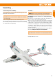
EasyStar 3 KIT / RR · Irrtum und Änderungen vorbehalten · 2019/10 · FP MULTIPLEX Modellsport GmbH & Co.KG · Westliche Gewerbestrasse 1 · D-75015 Bretten-Gölshausen www.multiplex-rc.