
User manual


14
pressed in, and then release the button again. The Status
LED ashes yellow at a high rate.
Prepare the receiver for binding
Place the transmitter and receiver close to each other.
Transmitter power is greatly reduced for the binding process;
the distance between the two units may need to be 20cm
or less. As soon as the transmitter and receiver have
“found” each other, the ashing rhythm on both components
changes to a slow rate. The servos connected to the receiver
will now follow the movement of the corresponding sticks.
The binding information is stored permanently in the
receiver, i.e. the binding procedure only needs to be carried
out once.
If you are using an ID receiver, you will hear an audible
signal when binding is complete, and the transmitter
automatically loads the appropriate settings.
4. Activating / disabling the throttle function
Regardless of the throttle stick position, the throttle channel
is initially disabled when the transmitter is rst switched on:
your model’s motor remains off. To control the motor in your
model you must rst unlock and activate the throttle channel.
You can also disable the throttle again after the landing.
To activate the throttle function you must press the throttle
stick button once briey, and move the throttle stick fully
back to the “Off” position. You will a rising signal.
To disable the throttle function, press the throttle stick button
again. You will hear a rising signal, and the motor is switched
off until the throttle channel is re-activated.
5. Initial test-run of the motor
Note: do not connect the ight battery to the speed controller
until you have switched on your transmitter, and are certain
that the control which operates the motor is at the “OFF”
position.
Check now the direction of rotation of the motor using
your radio control transmitter and the ight battery: when
viewed from the tail, the motor shaft must spin clockwise
(to the right).
Motor cut-off type: motor power reduction
=> A steady decline in motor speed is a indication that the
ight battery is almost discharged; you should initiate the
landing as soon as you become aware of this.
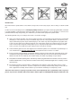
6. Tailplane panels
Temporarily t the tailplane panels on the fuselage by
pushing them together until the latch engages.
Fig. 4
To dismantle the system, locate the point marked “X” on the
tailplane 8, and press it in to release the retainer.
Fig. 5
Note: it is essential that the tailplane should pivot freely.
If the panels rub against the n, it may be necessary to
compress the foam slightly at the root face of the tailplane
panels. The easiest method of doing this is to place the
root face of the tailplane panel on the edge of a table, and
slide it to and fro using moderate pressure. Alternatively the
foam can be trimmed back very slightly using a balsa knife.
7. Wings
Temporarily t the wings on the fuselage by pushing them
together until the teeth engages.
The wings are separated by pulling the lug forward towards
the wing leading edge with one finger, until the teeth
disengage.
Fig. 6
Note: if the wing retainer system should become loose
after you have own the model for a while, push the wings
together slightly more rmly: this will engage one further
tooth, and the joint will become rm again.
8. Checking the model
Assemble the model completely, and ensure that the
airframe is “straight and square”. All the receiving system
components must be installed and connected correctly.
Check the control surface travels and the direction of
rotation of the servos. Ensure that all the mechanical control
systems are free-moving.
Fig. 7
Channel assignment
Channel 2: Elevator
Channel 3: Rudder
Throttle xed
9. Check the control surface travels (recommended
values only!)
The travels are measured at the widest point of each control
surface.
Elevator: 10 / 10 mm +/-
Rudder: 15 / 15 mm +/-
The tailplane is at the correct neutral point when the socket-
head grubscrew is visible through the hole in the side of
the fuselage.
Fig. 8
10. Setting the Centre of Gravity
The correct Centre of Gravity can be set by adjusting the
position of the ight battery, and by adding ballast if required.
The CG should be located 55 mm back from the wing
leading edge, measured where the wings meet the fuselage;
the position is indicated by small raised pimples on the
underside of the wings. Support the fully assembled model
on two ngertips: if balanced correctly, the fuselage should
now remain horizontal, with the nose inclined slightly down.
Fig. 9
If necessary, add trim ballast 30 to the chambers in the n,
then cover the recesses with the circular stickers from the
decal sheet.
Fig. 10
11. Pre-ight preparations
For the first flight please wait for a day with as little
breeze as possible; it is often worth waiting for the quieter
evening hours. If you are a beginner to radio-controlled
model aircraft, we strongly recommend that you ask an
experienced modeller to help you, as it is extremely likely
that things will go wrong if you try to “go it alone”. If in
doubt, contact your local model ying club. Your nearest
model shop will also be able to supply the address of clubs
in your area.