# 21 4276 Heron vorgesehen für den MULTIPLEX Brushless-Antrieb # 33 2660 / 33 3660 Designed for the MULTIPLEX brushless power set # 33 2660 / 33 3660 D GB F I ES Bauanleitung Building instructions Notice de construction Instruzioni di montaggio Instrucciones de montaje Ersatzteile Abbildungen Replacement parts Illustrations Pièces de rechanges Illustrations Parti di ricambio Illnstrazioni Repuestos Iiustraciónes ... 32 - 37 2 ... 13 14 ... 25 26 ... 43 44 ... 54 55 ...
Sicherheitshinweise für MULTIPLEX-Flugmodelle Das Modell ist KEIN SPIELZEUG im üblichen Sinne. D Mit Inbetriebnahme des Modells erklärt der Betreiber, dass er den Inhalt der Betriebsanleitung, besonders zu Sicherheitshinweisen, Wartungsarbeiten, Betriebsbeschränkungen und Mängel kennt und inhaltlich nachvollziehen kann. Dieses Modell darf nicht von Kindern unter 14 Jahren betrieben werden.
Restrisiken Auch wenn das Modell vorschriftsmäßig und unter Beachtung aller Sicherheitsaspekten betrieben wird, besteht immer ein gewisses Restrisiko. Eine Haftpflichtversicherung ist daher obligatorisch. Falls Sie in einen Verein oder Verband eintreten, können Sie diese Versicherung dort abschließen. Achten Sie auf ausreichenden Versicherungsschutz (Modellflugzeug mit Antrieb). Halten Sie Modelle und Fernsteuerung immer absolut in Ordnung.
KIT Heron # 21 4276 D Machen Sie sich mit dem Bausatz vertraut! MULTIPLEX - Modellbaukästen unterliegen während der Produktion einer ständigen Materialkontrolle. Wir hoffen, dass Sie mit dem Baukasteninhalt zufrieden sind. Wir bitten Sie jedoch, alle Teile (nach Stückliste) vor Verwendung zu prüfen, da bearbeitete Teile vom Umtausch ausgeschlossen sind. Sollte ein Bauteil einmal nicht in Ordnung sein, sind wir nach Überprüfung gern zur Nachbesserung oder zum Umtausch bereit.
Wichtiger Hinweis Dieses Modell ist nicht aus Styropor ™! Daher sind Verklebungen mit Weißleim, Polyurethan oder Epoxy nicht möglich. Diese Kleber haften nur oberflächlich und platzen im Ernstfall einfach ab. Verwenden Sie nur Cyanacrylat-/Sekundenkleber mittlerer Viskosität, vorzugsweise Zacki -ELAPOR® # 59 2727, der für ELAPOR® Partikelschaum optimierte und angepasste Sekundenkleber. Bei Verwendung von Zacki-ELAPOR® können Sie auf Kicker oder Aktivator weitgehend verzichten.
4. Verschlussklammern und Motorspant einkleben Kleben Sie die Verschlussklammern 22 rechts und links in die Rumpfhälften. Den Motorspant 50 mit Zacki ELAPOR® in die Aussparung der rechten Rumpfnase 4 kleben. Abb. 5 Setzen Sie die Servos gemäß der Abbildung ein. Es reicht aus, die Servos an den Laschen von Außen her mit Heißkleber zu sichern. So können diese im Reparaturfall einfach entnommen werden, ohne dass das Leitwerk beschädigt wird. Abb. 10 5.
16. Seitenruder freischneiden Schneiden Sie mit einem scharfen Messer den Spalt unterhalb des Seitenruders frei. Orientieren Sie sich beim Freischneiden an der vorgegebenen Struktur. Machen Sie das Ruder leichtgängig, indem Sie es mehrmals hin und her bewegen. Abb. 17 17. Ruderhorn und Anlenkung für Seitenruder fertigstellen Schrauben Sie den Inbus-Gewindestift 28 in den Kardanbolzen 27 und setzen Sie diesen in das Ruderhorn „Twin“ 26 ein.
27. Querruder- / Wölbklappenservos (Flaps) einbauen Stellen Sie die Servos zunächst in die Neutrallage. Montieren Sie dann die Servohebel 2 Zähne nach vorne gedreht zum Gehäuse (spiegelbildlich). Diese Einstellung ermöglicht die mechanische Differenzierung der Querruder, wenn das auf elektonischem Weg (Mischer) mit Ihrem Sender nicht möglich ist. Die Differenzierung ist nun mechanisch so abgestimmt, dass die Ruderausschläge nach oben grösser als nach unten sind.
37. Dekor anbringen Dem Bausatz liegt ein Dekorbogen 2 bei. Die einzelnen Schriftzüge und Embleme sind bereits ausgeschnitten und werden nach unserer Vorlage (Baukastenbild) oder nach eigenen Vorstellungen aufgeklebt. 38. Schwerpunkt auswiegen Um stabile Flugeigenschaften zu erzielen, muss Ihr Modell, wie jedes andere Flugzeug auch, an einer bestimmten Stelle im Gleichgewicht sein. Montieren Sie Ihr Modell flugfertig.
in der Ebene direkt „über Kopf“ zu erkennen und auszufliegen, ist nur den geübtesten Piloten möglich. Fliegen und suchen Sie deshalb immer querab von Ihrem Standort. Ein Aufwindfeld erkennen Sie am Flugverhalten des Modells. Bei guter Thermik ist ein kräftiges Steigen erkennbar - schwache Aufwindfelder erfordern ein geübtes Auge und das ganze Können des Piloten. Mit einiger Übung werden Sie im Gelände die Auslösepunkte für Thermik erkennen können.
auf unserer Homepage www.multiplexrc.de MULTIPLEX-Produkte sind von erfahrenen Modellfliegern aus der Praxis für die Praxis gemacht. Fliegen Sie verantwortungsbewusst! Anderen Leuten dicht über die Köpfe zu fliegen ist kein Zeichen für wirkliches Können, der wirkliche Könner hat dies nicht nötig. Weisen Sie auch andere Piloten in unser aller Interesse auf diese Tatsache hin. Fliegen Sie immer so, dass weder Sie noch andere in Gefahr kommen.
Stückliste KIT Heron # 21 4276 D Lfd. Stück Bezeichnung 1 1.1 2 3 4 5 6 7 8 9 10 11 12 1 1 1 1 1 1 1 1 1 1 1 1 1 20 21 22 23 25 26 26.1 27 28 29 30 30.1 31 32 33 34 35 36 37 38 39 40 41 42 43 Kleinteilesatz 3 Klettband Pilzkopf 3 Klettband Velours 2 Verschlussklammer 2 Verschlusszapfen 1 Befestigungsgurt für Akku 1 Ruderhorn „Twin“ 4 Ruderhorn „Twin 10x20“ 5 Kardanbolzen 5 Inbus-Gewindestift 1 Inbusschlüssel 2 Querrudergestänge m.Z.
Lfd. Stück Bezeichnung Material Abmessungen 63 64 65 66 67 Holmrohre und Gurte 2 Aussen-Holmrohr => im Flügel eingebaut! 2 Aussen-Holmrohr => im Flügel eingebaut! 2 Innen-Holmrohr => im Flügel eingebaut! 1 Rumpf-Verstärkungsrohr 4 Querruder / Flaps -Verstärkungsrohr CFK-4-kt. 5,5 x 3,5 x 200 mm ALU-4-kt. 10 x 8 x 900 mm CFK 4-kt. 8,8 x 6,9 x 1,5 x 900mm GFK-6-kt.
Safety Information for MULTIPLEX model aircraft This model is NOT A TOY in the usual sense of the term. GB By operating the model the owner affirms that he is aware of the content of the operating instructions, especially those sections which concern safety, maintenance, operating restrictions and faults, and is capable of fulfilling these requirements. This model must not be operated by any child under fourteen years of age.
Residual risks Even if the model is operated in the correct manner, and you observe all safety aspects, there is always a certain residual risk. For this reason it is mandatory to take out third-party liability insurance. If you join a club or flying association, insurance is usually available or included in the annual fee. Make sure that your insurance cover is adequate (i.e. that it covers powered model aircraft). Always keep your models and your radio control equipment in perfect order.
Heron KIT # 21 4276 GB Examine your kit carefully! MULTIPLEX model kits are subject to constant quality checks throughout the production process, and we sincerely hope that you are completely satisfied with the contents of your kit. However, we would ask you to check all the parts (referring to the Parts List) before you start construction, as we cannot exchange components which you have already modified.
Important note This model is not made of Styrofoam™, and it is not possible to glue the material using white glue, polyurethane or epoxy; these adhesives only produce superficial joints, and simply break away under stress. Please be sure to use medium-viscosity cyano-acrylate glue exclusively, preferably Zacki ELAPOR® # 59 2727, which is optimised specifically for ELAPOR® particle foam. If you se Zacki ELAPOR® there is usually no need for cyano ‘kicker’ or activator.
4. Gluing the latch catches and the motor bulkhead in the fuselage Glue the latch catches 22 in both fuselage shells (right and left). Glue the motor bulkhead 50 in the recess in the right-hand fuselage nose 4 using Zacki ELAPOR®. Fig. 5 5. Preparing the cable holders Use cyano to glue the socket of the 300 mm extension leads # 8 5031 to the cable holders 34, keeping the ends flush. Route the leads through the strain relief lugs as shown. Fig. 6 6.
17. Completing the rudder horn and linkage Fit the socket-head grubscrew 28 in the swivel connector barrel 27, and snap it into the “Twin” horn 26. Apply Zacki ELAPOR® / Hotglue to the recess for the horn, and push the horn into place as shown in the illustration. Engage the pre-formed end of the rudder pushrod 31 in the centre hole in the servo output arm, and slip the straight end of the rod through the hole in the swivel barrel 27.
Connect the aileron servo lead with the 400mm extension cords # 8 5029th Set the servos and the cable into the recesses of one. The connections of the power cable must be 46 mm above the root rib out. Secure the servos with hot glue to the tabs and insert the cable with transparent tape on the cable channel. Fig. 28 + 31 + 31b 28. Installing the root ribs Attach the retaining clips 55 to the left root rib 53 and right root rib 54 using the screws 37.
and / or glue the appropriate number of ballast balls 40 in the fin. We cannot state exactly how much ballast is required due to manufacturing tolerances in the foam density, and the different airborne equipment for the glider and electric glider versions. Mark the location of the airborne components in the fuselage once you have found the correct location, so that you can be sure always to replace the battery in the same position. Apply the fin sticker over the trim weight openings. Fig. 41 39.
and you will need a lot of skill to make use of them. With a little practice you will be able to recognise likely trigger points for thermals in the local landscape. The ground warms up in the sun’s heat, but heat absorption varies according to the type of terrain and the angle of the sun’s rays. The air over the warmer ground becomes warmer in turn, and the mass of warm air flows along close to the ground, driven by the breeze. Strong winds usually prevent thermal buildup.
models and your radio control system in perfect order at all times. Check and observe the correct charging procedure for the batteries you are using. Make use of all sensible safety systems and precautions which are advised for your system. An excellent source of practical accessories is the MULTIPLEX main catalogue or our website www. multiplex.de MULTIPLEX products are designed and manufactured exclusively by active modellers for practising modellers. Always fly with a responsible attitude.
GB Parts List Heron KIT # 21 4276 Part No. Description No. off Material Dimensions 1 1 1.1 1 2 1 3 1 4 1 5 1 6 1 7 1 8 1 9 1 10 1 11 1 12 1 Paper Paper Printed adhesive film Moulded Elapor foam Moulded Elapor foam Moulded Elapor foam Moulded Elapor foam Moulded Elapor foam Moulded Elapor foam Moulded Elapor foam Moulded Elapor foam Inj.
Part No. Description No. off Spars, longerons and stiffeners 63 2 Outer spar sleeve => in wing 64 2 Outer spar sleeve => in wing 65 2 Inner spar tube => in wing 66 1 Fuselage stiffening tube 67 4 Aileron / Flaps stiffening tube Material Dimensions Square CFRP Square aluminium Square CFRP Hex. GRP Stainless steel tube 5,5 x 3,5 x 200 mm 10 x 8 x 900 mm 8.8 x 6.9 x 1.5 x 900 12 A/F x 0.4 x 560 mm 3 Ø x 2.6 Ø x 330 mm * supplied length 650 mm => cut to length as listed below: 68 2 GRP rod GRP 68 1 R.H.
Consignes de sécurités pour les modèles volants MULTIPLEX Le modèle n’est PAS UN JOUET. F En utilisant ce modèle, le propriétaire de celui-ci déclare avoir pris connaissance du contenu de la notice d’utilisation, particulièrement concernant les consignes de sécurités, l’entretien ainsi que les restrictions et défauts d’utilisations, et qu’il a bien compris le sens de ces consignes Ce modèle ne doit pas être utilisé par des enfants de moins de 14 ans.
Ne volez jamais directement vers les personnes ou animaux. Volez le plus près possible au-dessus de personnes n’est pas une preuve de votre savoir-faire, mais expose ces personnes inutilement à un danger. Dans l’intérêt de tous, veillez en informer également les autres pilotes. Volez toujours de telle manière à ce que vous ne mettiez personne en danger. Pensez toujours que même la meilleure radiocommande peut être perturbée par des phénomènes externes.
F Heron KIT # 21 4276 Familiarisez-vous avec le kit d’assemblage! Les kits d’assemblages MULTIPLEX sont soumis pendant la production à des contrôles réguliers du matériel. Nous espérons que le contenu du kit répond à vos espérances. Nous vous prions de vérifier le contenu (suivant la liste des pièces) du kit avant l’assemblage, car les pièces utilisées ne sont pas échangées. Dans le cas où une pièce ne serait pas conforme, nous sommes disposés à la rectifier ou à l’échanger après contrôle.
Information importante Ce modèle n’est pas en polystyrène™! De ce fait un collage avec de la colle blanche, polyuréthane ou époxy n’est pas possible. Ces colles ne tiennent que superficiellement et cassent sous une contrainte trop importante. N’utilisez que des colles cyanoacrylate / colle rapide de viscosité moyenne, de préférence notre Zacki-ELAPOR® # 59 2727 qui est optimisé pour la mousse type ELAPOR® et colle rapide correspondante.
4. Collage des clips de fermetures et du support moteur Collez les clips de fermetures 22 dans la partie droite et gauche des demi-fuselages. Collez le support moteur 50 dans l’évidement du nez du demi-fuselage de droite 4 en utilisant du Zacki ELAPOR ®. Fig. 5 5. Préparation du support de câble Avec de la colle rapide, collez la prise du câble de rallonge de 300 mm # 8 5031 jointivement avec support de câble 34. Passez le câble dans le système de maintien. Fig. 6 6.
16. Libérez la dérive A l’aide d’un couteau bien affûté, libérez-la partie basse de la dérive. Pour cette opération, orientez vous à la structure pré dessinée. La dérive doit être maintenant bougée de gauche à droite pour la rendre plus mobile. Fig. 17 17. Mise en place du guignol et de la tringle de commande pour la dérive Vissez la vis de blocage six pans 28 sur le cardan 27 et placez l’ensemble sur le guignol „Twin“ 26.
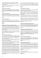
7 8 6 10 4 1 9 3 5 Abb. 1 75 82 54 53 29 76 40 41 21 23 20 22 56 50 80 61 37 33 62 55 25 79 72 81 60 73 74 77 38 43 32 51 52 34 35 30 58 30.1 31 12 36 39 42 59 26 57 11 66 69 (2x) 68 (2x) 67 (4x) 26.1 28 27 2 Abb.
326 326 69 243 218 282 400 215 68 Abb. 03 43 2 2x mm Ø 4 Ø2 x 2 28 mm L+R 22 m m m 26 m 18 Ø2 x2 Ø2 69 x3 50 Abb. 04 Abb. 05 34 34 4x # 8 5031 => 300 mm 34 Abb. 06 Abb. 07 4 66 52 Abb. 08 2x # 8 5032 => 600 mm Abb.
Nano-S # 6 5120 3 Abb. 11 Abb. 10 36 59 32 36 4 33 Abb. 12 Abb. 13 68 Ø1,3 x 215 mm (2x) 9 68 Abb. 14 Abb. 15 26 27 28 31 Abb. 18 57 Abb. 16 34 Abb.
75 82 79 76 80 72 73 74 77 Abb. 19 81 Abb. 20 25 38 39 51 43 43 12 Abb. 21 Abb. 22 68 Ø1,3 x 400 mm (2x) 6 58 68 6 Abb. 23 Abb. 24 ! 60 65 6 Abb. 25 Abb.
# 8 5029 => 400 mm 67 Nano-S # 6 5120 8 Abb. 27 Abb. 28 8 54 54 55 (2x) 37 Abb. 29 Querruder Aileron Abb. 30 30 (60 mm) 28 28 27 27 26.1 26.1 30.1 (70 mm) ! Wölbklappe Flap Abb. 31b Abb. 31 61 + 62 11 5 5 23 23 Abb. 32 36 Abb. 33 Abb.
Abb. 35 Abb. 36 35 (2x) 6 Abb. 37 Abb. 38 Motor Abb. 39 40 65 mm Abb. 40 Abb.
27. Mise ne place des servos d’ailerons / flaps Dans un premier temps placez les servos en position de neutre. Mettez en place le palonnier afin que celui-ci penche de deux crans en avant lorsque le servo est tourné pour la mise en position (miroité). Ce réglage permettra de compenser la différence mécanique de positionnement des ailerons lorsque cela n’est pas possible d’une manière électronique (mélangeur) au travers de votre émetteur.
La verrière est accrochée par l’arrière puis clipsé dans les tétons de fixations en appuyant sur la partie avant. Fig. 38 37. Mise en place de la décoration Vous trouverez un planche de décoration 2 dans le kit. Les emblèmes et les écritures sont déjà découpés, vous pouvez donc les coller selon notre exemple (image sur le carton d’emballage) ou en fonction de votre propre inspiration. 38.
évitez d’effectuer des ‘’virages serrés“ très près du sol. Atterrissez en toute sécurité et préférez la marche à pied que la réparation. 42. Le vol thermique L’utilisation des thermiques demande de l’expérience au niveau du pilotage. Les vents ascendants sur terrain plat – en fonction de votre altitude – sont plus difficilement identifiables au comportement de votre modèle que sur un terrain en pente, où les ‘’barbus’’ se situent plus à la hauteur de vos yeux.
47. Sécurité Sécurité est un maître mot dans le monde de l’aéromodélisme. Une assurance est obligatoire. Dans le cas où vous êtes membre au sein d’un club, vous pouvez y souscrire une assurance qui vous couvre suffisamment. Veillez à toujours être bien assuré (pour des modèles réduits avec moteur). Entretenez toujours correctement vos modèles et vos radiocommandes. Informez-vous sur la procédure de recharge des accus que vous utilisez. Mettre en œuvre toutes les dispositions de sécurités proposées.
F Liste des pièces du kit Heron # 21 4276 Nr. Nbr Désignation Matière Dimensions 1 1.
Nr. Nbr Désignation Matière Dimensions 63 64 65 66 67 Clé d’aile et renforts 2 Tube extérieur clé d’aile => mis en place dans l’aile! Fibre di carbonio verre 4-kt. 2 Tube extérieur clé d’aile => mis en place dans l’aile! ALU-4-kt. 2 Tube intérieur clé d’aile => mis en place dans l’aile! Fibre di carbonio verre 4-kt. 1 Tube de renfort fuselage Fibre de verre-6-kt.
Sicurezza per gli aeromodelli MULTIPLEX Il modello NON È UN GIOCATTOLO nel senso comune del termine. I Con la messa in funzione del modello l’utente dichiara di conoscere e aver capito il contenuto delle istruzioni per l’uso, in particolare le avvertenze sulla sicurezza, gli interventi di manutenzione, le limitazioni di funzionamento e i vizi. Questo modello non deve essere messo in funzione da bambini di età inferiore ai 14 anni.
Rischi residui Anche se il modello viene messo in funzione secondo le norme e tenendo conto di tutti gli aspetti di sicurezza, sussiste sempre un determinato rischio residuo. Quindi è obbligatorio stipulare un’assicurazione di responsabilità civile. Nel caso foste socio di un’associazione o federazione, potete stipulare l’assicurazione anche in questa istituzione. Fare attenzione ad avere una protezione assicurativa sufficiente (aeromodello con motorizzazione).
I KIT Heron # 21 4276 Acquistate familiarità con il kit di montaggio! Le scatole di costruzione per modelli MULTIPLEX sono soggette, in fase di costruzione, a continui controlli relativi alla qualità del materiale. Ci aguriamo che siate soddisfatti del contenuto della scatola di costruzione. Vi preghiamo comunque di verificare tutti i pezzi (in base alla distinta) prima dell’uso, in quanto i componenti già utilizzati per il montaggio sono esclusi dal diritto di sostituzione.
Nota importante Questo modello non è in Styropor ™! Pertanto non è possibile incollare con colla vinilica, poliuretano o colla epoxy. Queste colle aderiscono solo superficialmente e non tengono in caso di emergenza. Utilizzare unicamente colla istantanea in cianoacrilato a viscosità media, preferibilmente Zacki ELAPOR® # 59 2727, perfezionata e adattata all’espanso ELAPOR®. Se utilizzate i prodotti Zacki-ELAPOR® potete rinunciare per lo più all’uso di kicker e attivatore.
4. Incollare i clip di chiusura e l’ordinata motore Incollare i clip di chiusura 22 a destra e a sinistra nei semigusci della fusoliera. Incollare l’ordinata motore 50 con Zacki ELAPOR® nella cavità della punta destra della fusoliera 4 . Fig. 5 5. Preparare il fermacavi Incollare con colla istantanea la presa del cavo di prolunga da 300mm # 8 5031 a raso nel fermacavi 34. Inserire il cavo attraverso la linguetta dello scarico della trazione. Fig. 6 6.
16. Tagliare la direzionale Tagliare con un coltello affilato la fessura sotto la direzionale. Durante il taglio orientarsi alla struttura predefinita. Fare in modo che il timone possa essere mosso facilmente muovendolo più volte. Fig. 17 17. Finire la squadretta per timone e l’articolazione per la direzionale Avvitare il grano a brugola 28 nel perno cardanico 27 ed inserirlo nella squadretta per timone “Twin” 26 . Zacki ELAPOR® / colla a caldo viene applicato nella “fessura” per la squadretta per timone.
zione meccanica degli alettoni, quando non è più possibile in modo elettronico (mixer) con la vostra radio. La differenziazione è quindi adattata meccanicamente in modo che le escursioni del timone verso l’alto siano maggiori che verso il basso. Utilizzare questa impostazione per ottenere ancora maggiori deviazioni per la posizione di atterraggio farfalla. Il servi lembo in posizione neutra il braccio del servo di ruotare 2 denti nella parte posteriore - custodia (immagine speculare) per.
ogni altro aereo, deve essere equilibrato in un determinato punto. Montare il vostro modello sino a quando è pronto al volo. Il baricentro è contrassegnato a 65 mm dallo spigolo anteriore dell’ala portante (misurato alla fusoliera). Qui sul lato inferiore si deve bilanciare il modello in posizione orizzontale con l’aiuto delle dita.
Un campo ascendente si riconosce dal comportamento del modello; le buone termiche fanno salire velocemente il modello, le piccole, invece, richiedono tutta l’esperienza del pilota. Con qualche esercizio si riuscirà a riconoscere i punti di distacco delle termiche nell’area di volo. L’aria si riscalda, a seconda della capacità del terreno di trasmettere il calore del sole e viene spostata dal vento a poca distanza da terra.
I mando migliore può in ogni momento essere soggetto ad interferenze esterne. Anche anni di esperienza pratica, priva di incidenti non è una garanzia per i prossimi minuti di volo. Prima di ogni avvio controllare che il pacco batteria sia ben fisso nella sua sede, inoltre controllare anche le ali e i piani di coda. Controllare anche che tutti i timoni funzionino correttamente! Noi, il team della MULTIPLEX vi auguriamo buon divertimento e tanto successo durante l’assemblaggio e anche dopo, durante il volo.
Numero progressivo Pezzo Designazione Materiale Dimensioni 50 51 52 53 54 55 56 57 58 59 60 61 62 Set componenti in materiale plastico 1 Ordinata motore 1 Piastra portante pacco batteria 1 Passaruota 1 Centina alla radice a sinistra 1 Centina alla radice a destra 4 Clip di fissaggio 1 Perno di arresto 1 Ruotino di coda (finto) 1 Supporto impennaggio elevatore 1 Controsupporto impennaggio elevatore (per dadi) 1 Squadretta per timone impennaggio elevatore 1 Carenatura servo a sinistra 1 Carenatura serv
Cuaderno de seguridad para modelos de aviones MULTIPLEX El modelo NO ES UN JUGUETE en el sentido habitual de la palabra. E Con la puesta en marcha del modelo, el operador declara que conoce el contenido del manual de instrucciones, especialmente lo respectivo a consejos de seguridad, trabajos de mantenimiento y limitaciones de uso y carencias, pudiendo cumplir todo lo requerido. Este modelo no debe ser manejado por menores de 14 años.
Otros riesgos Incluso utilizando el modelo según las normas y respetando todos los aspectos de seguridad, siempre hay un riesgo determinado. Por tanto, un seguro de responsabilidad civil es obligatorio. En caso de que vaya a entrar en un club o una asociación, puede realizar la gestión del seguro por esa vía. Preste atención a los aspectos cubiertos por el seguro (aviones con motor). Mantenga siempre los modelos y la emisora en perfecto estado.
E KIT Heron # 21 4276 ¡Familiarícese con su Kit! Durante la producción, los kits de MULTIPLEX se someten a continuos controles de material. Esperamos que el contenido del kit sea de su agrado. Aun así, le rogamos, que compruebe que todas las piezas (según la lista de componentes) están incluidas antes de empezar a montar, ya que cualquier pieza que haya sido manipulada no podrá cambiarse.
Aviso importante: ¡Este modelo no es de Styropor ™! Por tanto, no debe usar cola blanca, poliuretano o Epoxy para las uniones. Estos pegamentos solo producen una unión superficial y que se despega fácilmente. Utilice exclusivamente pegamentos con base de cianocrilato de viscosidad media, preferentemente Zacki -ELAPOR® # 59 2727, que está optimizado para las partículas de ELAPOR® y un pegamento instantáneo compatible. Al utilizar Zacki-ELAPOR® podría ahorrarse el uso de activador.
4. Pegado de las pestañas de cierre y la cuaderna parallamas Pegue las pestañas de cierre 22 a izquierda y derecha en las mitades del fuselaje. Pegue la cuaderna parallamas 50, usando Zacki ELAPOR®, en la ranura del morro derecho 4. Img. 5 5. Preparación del fija cables Use cianocrilato para pegar firmemente el conector del cable prolongador de 300mm. # 8 5031 en el fija cables. Haga pasar el cable a través de la solapa del protector contra tirones. Img. 6 6.
16. Liberar el timón de dirección Use una cuchilla afilada para cortar a ranura de la mitad inferior del timón de dirección. Para ello, use la estructura predefinida como orientación. Haga funcional el timón, moviéndolo varias veces a uno y otro lado. Img. 17 17. Preparar el horn y la transmisión para el timón de dirección Enrosque el prisionero allen 28 en los cardan 27 y coloque estos en el horn „Twin“ 26 del timón. Se aplica Zacki ELAPOR® / pegamento caliente en el „nido“ del horn del timón.
27. Montar los alerones / flaps de los servos Comience poniendo los servos en posición neutral. Después, monte el brazo del servo justo 2 dientes hace adelante respecto a la carcasa (visto en un espejo). Este ajuste posibilita el diferencial mecánico de los alerones, siempre que su emisora no disponga de recorrido (mezclador) electrónico . El diferencial se ajusta mecánicamente de tal modo que el recorrido de los timones sea mayor hacia arriba que hacia abajo.
37. Colocar la decoración EL kit incluye láminas decorativas. Los motivos y decoraciones incluidos, ya vienen recortados y podrá seguir nuestro modelo para decorar el suyo, o definir su aspecto a su gusto. 38. Equilibrar el centro de gravedad. Para conseguir un vuelo estable, su modelo, al igual que cualquier otro avión, necesita que su centro de gravedad coincida con un punto determinado. Termine de montar su modelo.
42. Vuelo en térmicas Los pilotos necesitan algo de experiencia para poder aprovechar las térmicas. En las llanuras, la presencia de térmicas y como estas afectan al vuelo del modelo, es bastante más difícil de detectar que en una ladera – en el llano, el modelo vuela muy alto mientras que en las laderas, el modelo suele estar en „a la altura de los ojos“, siendo más fácil apreciar como se ve afectado por la corriente ascendente.
por la carga alar (cuanto más baja, menor será). Por tanto, el modelo puede tomar curvas muy cerradas – algo realmente ventajoso cuando se vuela en térmicas (Las térmicas cerca del suelo son muy cerradas). Infórmese acerca de las técnicas de carga de las baterías que vaya a utilizar. Utilice las medidas de seguridad más lógicas que estén disponibles. Infórmese en nuestro catálogo principal o en nuestra página Web www.multiplexrc.de El otro parámetro importante es el ángulo de planeo.
Nr. Uds. Descripción Material Dimensiones 33 34 35 36 37 38 39 40 41 42 43 1 2 2 2 4 1 1 2 2 3 2 Metal Plástico inyectado Plástico inyectado Metal Metal Metal Metal Bolas de metal Plástico Plástico Plástico M2 Pieza prefabricada M5 x 35 mm. M5 2,2 x 6,5 mm. M3 x 30 mm. M3 Ø13mm / 9 gr. 8 x 2 mm. 98 x 2,5 mm. Ø3,1 x Ø6 x 4 mm.
Fuselage shell L.H./R.H. with tail Fuselage nose glider Left fin moulding GRP rod Ø 2x800mm GRP rod Ø 1,3x650mm Fuselage stiffening tube Rumpfhälfte links, rechts m.
Rumpf-Verstärkungsrohr Fuselage stiffening tube Tube de renfort fuselage Rumpfnase Segler Fuselage nose glider Nez de planeur Höhenleitwerk Tailplane Profondeur GFK-Stab Ø 1,3x510mm GRP rod Tube fibre de verre St. = Stück, Piece, Pièce 6 68 x2 # 22 4395 Höhenleitwerk/ Tailplane/ Profondeur 69 x2 68 66 10 GFK-Stab Ø 2x800mm GRP rod Tube fibre de verre GFK-Stab Ø 1,3x650mm GRP rod Tube fibre de verre Seitenleitwerk links Left fin moulding Dérive de gauche 67 x4 (# 70 3457) 2 St.
Anleitung HERON # 94 4772 (20141022 BEDO) Irrtum und Änderungen vorbehalten © MULTIPLEX MULTIPLEX Modellsport GmbH & Co.KG 68 Westliche Gewerbestrasse 1 D-75015 Bretten-Gölshausen www.multiplex-rc.