Contents Page Page Adiusting the transmilter controls lntroduction mc3010......... tothePRoFI welcome Animoortantdifference........................................ Aboutthismanual................. The legalside Quickstart ....i, I. The transmitter The hardware ..........................4 frontface.notesonoDeration Transmitter andclosingthetransmitter, Opening .......................5 theRFmodule changing p a n e l . . . . . . . . . . . . . . . . . . . . ..................................
.....65 ..TRANSMITTER CONTROLTEST..menu .....66 The Äccessories ............6 . .7. . S t i c kt o p s . . . . .67 . . . . . . . . . . . . . . . . . . . . i n s t a l l i n s g w i t c h e s F l e l o c a t i nagn d . . . . . . . . . . ..68 w e a t h e s r h i e l d H a n ds u p p o r t s , For Experts "in flight" ............68 memories Switching 2 .....................69 with more than ailerons Assigning servos ..................................69 T h e" S l "s w i t c h programs ..............
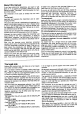
- Welcometo the PROFImc 3010 a Well.tirstot all.the PROFImc3010is capableof much the PROFImc 3010youhaveacquired In purchasing quality, of productof the highest withall the advantages morethan you can imagine- and we wouldhateto "Made we haveput a lotol fromyou.Secondly, Wethankyoufor yourfaith hideanything in Germany". being can that any modeller this a manual into making eftort Inourcompany. - everything in full.
Aboutthis manual to applyto you,skipit for now,and readit lateron' perhapswhenyoufindthatyoureallydo needit' lf vou are an old handat this sortof thing,pleasebe suie to readwith particularcarethe Sectionswhichare " concernedwith memories,switchingmemories in switch.Theseare the facilities flioht".and withanyotherradiocontrolset. not available wfrich.are The tirst part: and its wide- The secondpart: describesand explainsthe transmitter of basically consisting system: dealswiththe receiving facilities.
Wewill assumethat it hasworkedconectly.Nowpress the Il key.The numberin line 2 startsto flash.Now pressthe E or El key untilthe number01 appears.lt After purchasinga new radio control system most shouldalsobeflashing. wantto seeit in actionas quicklyas possible Nowpressthe E keytourtimes;you are finished,and modellers - to findoutwhetherit works,if nothingelse.lf thisde- will see the startingdisplayagain,exceptthat now brief memorynumber01willbedisplayed: fits,thenthissectionis toryou.
at thisstage: 8. Youcouldmeeta slightproblem in memory are for the "PPM" models stored All the mode. transmission yourPROFImc3010witha PCM lf youhavepurchased receive(you mustnowswitchto the correcttransmissionmode. Todo this,pressthesekeysin succession @Z tr, and youwillseethisdisplay: I tlti:FFt,ltr t'1üt:'ULHT Pressthe Z key,and"PPMg"willtlash.Nowpressthe El key,and"PPMg"willturninto"PCM". Pressthe @ key threetimes,and you will be backto Thejob is done. screen. thestarting off andon again(it's 9.
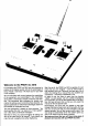
Fig.2 Transmittercontrol symbols All of the controlsare designatedby a letter;for exampianeof the left-handstickunit, ole B is the forward/att and C is right/lefton the right-handstick.Theseletters are a usefulshorthandmethodol referringto the controls.Theselettersymbolsare used all the time in this text,and you will usethemwheneveryou usethe transmitter. Stick unit trims (Fig.3) stick Basicallythe trims - apartfromthe throttle/spoiler - workon the "Centre-Trim" principle.
thereby Thiswillhelpto ensurethatit is fittedsquarely, Changingthe RF module;changingcrystals avoiding damage to the contacts. Graspthe moduleat the recessedpoints(Fig.7), then oull it uo and out of its holder. The crystalis pluggedinto the side of the RF module (Fig. 8). Pull out the crystalby its plastictag. When pluggingin a crystalmakesure that both pins engage correctlyin the socketin the module. Beforepluggingthe modulein again,bend the plastic tag overto one side.
F "F".Thisis normally slidercontrol. theright-hand Control T Canbepluggedin eitherwayround. Keypad. G Plugit channel. thisis a switched Control"G". Normally of operation wayroundandthedirection in theopposile channelis reversed. ol theswitched H ,l Controls version. Notusedin thestandard cialpurposes. KnL stickunit. Left-hand 51 to 55 51 to 55. switches Inputsfor the change-over/coupling Moreonthison page12. US switch.
F i g .1 8 of theMULTIPLEX ComYoucanusetheearlierversion the batOrderNo. 14 5540,to slow-charge bi-Charger, tery In thiscaseselectthe 100mAchargecurrentand chargefor at least24 hours.At this currentyou can to the chargerconleavethe transmitter connected stantly;it is not possibleto damagethe batteryor the at sucha lowcurrent. transmitter off beJorerecharging. Be sureto switchthe transmitter (chargesocket)to the Then connectthe transmitter chargerusingthechargeleadsupplied.
then releaseit whenthe requiredvalueis reached.lf you "overshoot",press the oppositekey to go back if youwishto changea mixerinput again.Forinstance, easierthantappingthe from0 to 70,this is somewhat E key70times. (seepage it makessense,the Digi-Adiustor Whenever in parallel withthesetwokeys.Youcan 5) is connected thenchoosewhetherthe keysor the rotaryknobis the to use. moreconvenient keys TheIZZN Theseare the "selector" or "afto^ " keys.
PROFImc 3O1O EURO-LINE menustructure BB Eh FIE5TFI FPI'I:T F I E5Tll : IEl PFll9 t. 5r:rr.rllllllErEr Sheet1 l. SBU llllll tlB | 2B Menu 1 Filenumber'1 ...30,Fx File name,I characters Transmissionmode Batteryvoltage,digital Batteryvoltage,bar graph,6 blocks periodin hoursrminutes Operating r_;EEtJr_r r-:r:rt.lTF:üLt rF I LE!; l'lEHUfu SERVO MEMORY CONTROL r T H L I + F l ELt JI l.l l T r 7L:tlPV Htll,lEt rl:El.lTFiE5lrllTt-Hr r5H I FT t-:H1".. TEI l'1.i !:ET UF'\ rtlül'lEr I -::trl.
EURO-LINE PROFIMC3O1O Menustructure r T E r . r + F E L rI I. ' l I T ! rr-:El.lTEE5tilI TtlHr 7 : : E F l::. E L E L + 1 5 E Fil:. E L E U+. r ! : E E . l : E L E \ .+r . T, l:lt{ + . / ü : 1 . I r:;Fl.tI L: r+lBtlil F+ ELEl..lF/I : E H T E E : E L E L+I . + 1LlE:.:/ SwitchmixerinputsON/OFF and assignswitchesto inputs Adjusttraveland set directionfor: @ ntes rl:ilF'i HF,tl'lEr TF:ll'1r r:;H I FT t_:H1.,. rl{u[:'E : FULL r:1b: FIE5TH \FFll'.
or coupling in a similarwayto oneof the change€ver with a transmitter in combination especially switches; t . r control. ' , of thesespecialfeatureswouldonly An explanation matters at thispoint.Pleaseseepage69 in the confuse dry andtheoreti- Sectionentitled" Forexperts". Thissectionis necessarily somewhat cal, and you can skip it for the momentil you wish. Nowwe cometo one furtherdifterence,and a possiHowever, sooneror lateryou will needto absorbsome ble sourceof confusion.
Thesecondline: r:r.i4r.IllIIII After the bar display: rlrl:2+ batteryvohage.Thedigitalvalueis A veryusefulleature: 8.24Y = transmitter not easyto assimilate The operatingperioddisplay very accurate,but unfortunately lm- At any time you can see how long the transmitterhas of all digitaldisplays. at firstglance- a drawback mediately aftera full chargethe voltageis about8.2- beenin use sincethe lasttime the timerwas resetto 8.4V.At 6.
("ready made lists') No. 6 to form,memories In the transmitter's standard modellists(orproNo.15contain"readyprogrammed" grams).Theseexampleprogramsembracea high perflownby praccentage of themodelswhichareactually tisingmodellers. Youcan useanyof theseexamplelistsiust by switching to the appropriatememoryas describedon page43. Beforeyou fly your model,you may well haveto alter the directionof servorotation,andthat is describedon page28. Youmayliketo usetheseexamples asthe startingpoint for your own lists.
"FIESTA" Example: MemoryNo.:6 of a simplemodelglider. atedby a switchedchannel.A mixeris featuredto proThe "FIESTA'is an example when airbrakesare exby a singleservo(mechani- vide pitch trim compensation Theailerons arecontrolled input is set to zero as However, the mixing The airbrakesare operatedwith the tended. cal differential). "Combi-Switch" has to set the valueif he needs and the user standard, An aero-tow supported. left-handstick. feature.
"SALTO" Example: MemoryNo.:7 roothaveinherentaeroof a modelwitha V{ail.At whichdo notreachto the wing The "Salto"is an example "flapinput"shouldbe kept the disadvantages, dynamic 2 rotating trailing edge wing are endof each theinboard to whichare usedto loseheightand to control small,and theyshouldonlybe usedfor aerobatics spoilers, Forthisreasonthe flap input by two improvemanoeuvrability. Theailerons areoperated the landingapproach. Theyare alsoset can be switchedoff by meansof the switch53.
model:'FgB" Example MemoryNo.:I modThepictureshowsa typicalF3Bclasscompetition el. The controlsystemis quitecomplex.Eachaileron and eachflap is operatedby its ownservo.Thismakes "Quadro"and "aileronbrake"(crow)controlsystems possible. supportthe camIn normaltlightthe ailerons ber-changingflaps,and vice versa;for landingthe Jullyup flapsaredeflectedfullydownandthe ailerons is ("aileronbrake"function).
model:"CORTINA" Example MemoryNo.:9 "Cortina"is a typicalexample glider. Themixingratiosfor elevatorandaileronaredifferentfor of a modern tailless A seoarate servois reelevons. Controlis achievedwith two controlsurfacesper wing theinboardandoutboard forheight panel,eachsurtaceworkingas combinedelevatorand quiredforeachelevon.Airbrakes areincluded Thisarrangement makesit possible to dumpingand landingapproachcontrol.The aerotow aileron(elevons). is actuated viaa switched channel.
model:"BlGLIFT" Example MemoryNo.10 The "Big Litt" representsa simple poweredmodel. standardcontrols.An aero-towreleasecan be operated channel. Aileronsand landingflapsaretittedin additionto the viatheswitched Summary: 5 3 2 AILERON THROTTLE RUDDER]ELEVATOR FLAP 1 6 AERO.
model:"RC1/F34" Example MemoryNo.:11 Mixturecontrolin Examoleof an F3A class comoetitionmodel.The spoilersarefitted,actingas airbrakes. to throttlecontrol.A furtherservocanbe titted to aF addition areeachcontrolled by a separate aileron, ailerons via the switchedchannel. low the optimumdegreeof differentialto be set. Two to retractthe undercarriage Summary: Channel Throttle controls ServoNo Function L. AIL. RUDDER ROTTLE R. AIL. Spoiler MIXTURE UNDERC servotravelinsteadof DualRates.
model: " MIRAGE" Example Memory:No.:12 can be retractedvia the switched The "Mirage"is a simpledeltamodel.lt is controlled The undercarriage withthe helpof a plusrudder channel.Theelevonsarecontrolled (elevons), via combinedailerons/elevators LrtsLtAmtxer. andthrottle. Summary: r Channel controls Throttle D ry9q91 Elgy"to, ServoNo Function Mixer 'lstinp. DELTA DELTA ELEVATORELEVATOR RUDDER THROTTLE 2nd inp. AILERON AILERON L elevon Undercarr.
model:"HELIBOY" Example MemoryNo.:13 This,of course,is just a starting with swash- steadof "DYN.THR.". Exampleof a "simple"modelhelicopter, pitch, ooint. plate having no axial movement.Collective type.Youcanswitch is a "suppressible" pitch-axisand roll-axisare controlledby one servo Gyroassumed " each. FLAREmixer used lot flarc" compensation. betweenminimumand maximumgyro effectusing G.
model:"RANGER" Example MemoryNo.:14 acwiththe "Heim"swashplate of a helicopter Example is actuatedby two tuation system.The swashplate"HElMHEAD" pitchservos, mixer andthe roll/collective control.In is used.A separateservoprovidespitch-axis "DYNTHR." is used. thisexample gyro is assumed,which can be A "suppressible" switchedbetweenmaximumand minimumeffectby controlH.
model:'B,K117" Example control with"CPM"swashplate ExamDle of a helicoDter is controlleddirectlyby 3 sersystem.The swashplate vos,arrangedat 120degreesto eachother,whichproand roll-axiscontrol. vide collectivepitch,pitch-axis Three servos are used, in conjunctionwith the "HEAD-MlX"mixer. The throttle is assignedto MemoryNo.:15 "THROTTLE" ('DYNIHR.'is an alternative). A "suppressible" gyrois assumed, bewhichcanbe switched tween minimumand maximumeffectby meansof by switched controlH.
i: i,: control controls, or linkingup,thetransmitter Assigning functionsandservosis the firstand mostimportantpart ot the settingup processwhichhasto be carriedout beloreyou can actuallyusethe equipmentto controla new model.But don'trun and hide - there'snothing waitingforyou. verycomplicated li you haveownedanotherradiocontrolsystembeJore alreadycar the "PROFImc 3010",you haveprobably "assigning" process it.
We have"pre-defined"thesefunctionsfor you so that That'salmostall thereis to it. Butwhatof the unused you don'thaveto typeanythingin; all you haveto do is controls (8, E, G,H, D? selectthe rightoption.Thereis alsoanotherreason:if Thereis a dangerherethatsomething hasalreadybeen you selectthe termsfromthe list above,your "intelli- assignedto thesecontrolswhenthe memorywaslastin gent"transmitter worksout whatyou are likelyto ask use - something whichcouldcauseproblems.
Pressthe N key.The "1" startsto flash.Moveon, or "leafthrough", the E or E keys.Thenumby pressing bersriseto 9,thenstartagainfrom1. andpress stopat No.3 ("3" flashing), As an example, the Z key. andtheservofunctionin the The"3" willstopflashing, AILERON ELEV(aro0 RUDDER THROTTLE 2.THBOI SPOILER FLAP BETRAT. TOWHOOK MIXTURE ROLL PITCH YAW(tailrot) COLL.PITCH GYRO bottomlinewillllashinstead.Hereagainyoucan leaf throughtheoptionswiththe E and El keysandassign thecorrectfunctionto thatservo.
Finallya practicalexamplein abbreviatedform. N key;thenleafthroughwithEl keyuntil"2" flashes. A model glider with elevatorand rudder,differential Z key;leafthroughuntil"ELEV"appears. sooilersand aero{owrelease(the"FLAMIN- N key;move ailerons. GO" again). Z key;lealthroughwiththe El keyuntil'RUDDER' Firstyoumaketheconnections end: appears. at thereceiver key; leafbackto "1" withthe El key. N Elevatoris operatedby servoNo.2 Rudderis operatedby servoNo.
travel,or utilisethetraveladjustactlyequalmechanical mentfacility. A Dointto notehereis that eachservomusthave"its Iimits,youcanadjustthe neutralpo- own" receiveroutput;otherwiseit is not possibleto ad' Withinreasonable (usethe faoutput. just the travelof eachservoindependently to eachreceiver the servos connected sitionof funccontrol to one multiple servos assigning cility of What'sthe point of that? page 26).
to feelat homewiththesystem? Areyoubeginning which correspondsto moving the The servo travel is and then adiusted by the left selected to stick "stick |eft". The servo travel which correspondsto moving the stick to the right is selectedand then adiustedby "stickright". lf younowmovethe stickto rightandthenleftyouwill see that the travelvalue alternatesbetween80 and 900/o. Caution- a trap for the unwary!Pleasedon'tsetthe Theresultwould travelto zeroon bothsidesol neutral. bethattheservodoesnotmoveat all.
worksthewrongwayround, movement of yourailerons pleaseseepage33.
adjustment: Travel, symmetrical Howto set Ailerons only. transmittercontroloptions Centreadjustment: the characterisAs we are nowtalkingaboutadjusting flapandspoiler. exceptthrottle, Alltunctions moveto the "Transmitter controls, tics of transmitter ldletrim: ControlAdiustment"menu. Throttle andspoileronly. Fromthe Statusdisplayyou reachthe menuwiththe Differential: sequenceEINN.
round! Thisentire"switchcorner"onlyappearson thescreen themselves Caution- don'tturn the switches They mustbe installedas dictatedby the Transmitter whenyou are dealingwithan optionwhichrequiresa switch;for fixed-wingmodelsthese are ControlTeston page66; otherwisethe wholearrange- mechanical "Dual Flates" and"FixedValue". mentwillbe uoset. in one Dual Ratesreducesservotravelequallyin both direcThe asterisk(star)whichappearsafterthe arrow switch.
The "symmetricaltraveladjustment" option forailerons. A traveladjustThisoptionis onlyavailable wouldmakeno mentfacilityfor bothsidesseparately aileronservosthe efsensehere;withtwo differential hadbeenapfectwouldbe the sameas if difterential olied. lf you havealreadytriedout someot the optionsdescribedabove,youwill haveno troublesettingup this function; it is carriedoutin exactly thesameway. = maximum Hereagain:1000/o travel;00/o= notravel Fig.23 The"CentreTrim"option for mostcontrolfunctions.
The"ldleTrim"option oJthis optionis thatyou can advantage The practical withoutaftec! carburettor idle setting of the adjust the for the "THROTTLE" con- ingitslull-throttle Thisoptionis onlyavailable position. lts effectis thatthethrottrolfunction(orTHROTTLE-2). this optionis the sameas for and adjusting whenthestickis at Selecting tle sticktrimslideris onlyeffective described. the other options already towards ltseffectis steadilyreduced its "idle"position. range: of the stick.
"in parallel"withthe El is connected The Digi-Adjustor andEl keys,and hasexactlythesameeffect,namelyol Allyouneedto do in thedegreeof differential. adjusting whilethemodelis thiscaseisto rotatetheDigi-Adjustor flying(don'tlookdownat it!)untilyouaresatisfied. the Landthe model,thenleavethe menuby pressing gets there's (everything automatically stored E] key nothingmoreto bedone). Caution! Although it is theoretically possible, you should neveraitemptto makechangesvia the keypadwhile the modelis flying.
Pressthe N keyagain.Go past"S5" withthe E key; for afterthe displays"LS", "H" (controlH is reserved the Profimc 3030)and "1",the symbol51 appears again,but this timefollowedby the symbolinsteadof that a momentary switchis the arrow.This indicates now"expected". lf youwishto tryoutthisoptionyouwill,of course,have switch. to installa momentary Pressthemomentary switch.ServoNo.6 willrunto the pre-setFixedValue.Nexttimeyoupressthe buttonthe to theslideragain,andsoon.
lhe Howto use "Com$-8vvitch" is to helDthe less Now,after this necessarypreamble,to the matterin The mainuse of the Combi-Switch pilothandlethe moredemanding formsof hand: experienced reasons manyglidersre- Youcannotset up the Combi-Switch modelglider.Foraerodynamic untilyou havealouireco-ordinated controlol rudderandaileronsin or- readyassigned onetransmitter controlto aileronsand However, oneto rudder.Youwillalsoneedto installa switchfor derto flya smoothturn- justlikethefull-size.
lf you want to adiustthe followingrate in flight (Digirequired): Adjustor Beforelaunching the model,moveto the menuas depress theZ key,to release thevalueinput scribedand field.Don'tleavethe menu!Whileyou are flyingyour modelyou can nowvarythe valueof the followingrate Landthe modeland press by rotatingthe Digi-Adjustor. the @ keyto storethe valueyou havefoundto be correct. Caution! Neverattemptto makechangesvia the keypadwhile the modelis flying.
lf you makeany changes(e.9.to the trims,to servo terms. Wedon'tmindi{youwantto usetheordinary is althe modification "list" here,becausethat is travel,to mixingratiosetc.),then We have used the word "current" list)automati(the list in the ways recorded foreachmodel, assembles actually whatthetransmitter Whenyouswitchoff,the memoryis than a "pro- cally,immediately. to imagine list is easier a because and "uPto date". always therefore gram".
The"Copy"Menu "Mode:" is the routeto severalpossiblevariations from " procedure. the simple copying We will discuss these From the Status Displayyou reach the Memory" "normal" Menuwith the key sequence@S, and movefrom later.At the momentwe willonlydiscussthe thereto the"Copy"MenuwiththeZ key.Youwillthen copyingprocess,whichis usedmostfrequently. seethis: rl'lü[iE : FULL rFF:f' 15: l.
The"TRANSMITTER CONTROU' copyingmode Earlieron in this Copyingsectionwe usedthe "ALL" for everymodel.lf youacquirea newmodel,in which you can use is different, copymode.Thissimplycopiesthe entire"list",i.e.all onlythe servoarrangement controlsand thiscopyingmodeinsteadof the normalassigning and assignments and settingsof transmitter procedure for the transmitter controls. For servos,intothe newmemory. adjustment or models As you havealreadyseenwhenyou leafedthroughto the morecomplexmodels(e.9.
The"SHIFT"Menu the newmodel.Thetransmitter cannotdo it by itself;it hasplentyof brainpower,but no musclepower. menuappears Tocaterfoi this,the "TRIMPOSITION" whenyoushiftmemories. automatically Howto switch models overto anothermodel- it To switchthe transmitter mustalreadybe storedin a memory,of course- you just needto "callit up".Youdon'tneedto worryabout 5T I til'; rr H 11t r l-r' l -r-.. L l-rJ the "current"model(the modelin use beloreyou r i r i '+' i.e.youdo nothaveto "save"it first.
whichyouwillseealternat The "underline" character, letter,is knownas the cursor:the ing withthe Jlashing Withoutthe cursor cursormarksthe currentposition. youwouldnotseeanythingat a blankspace. showsthenumberandname Enterthe newnameletterby letter.lf you lookcaretully Thedisplayautomatically of the "current"model.In our examolethis is No.06 whenyoupressthe El andE keys,youwillseethatthe and"FLAMINGO".
youwillgetto knowthemixerswhichthe Forthis reasonwe will firstdiscussour newmethodof In thisSection mixers. Youwillseethattheconceptfitsin transmitter hasto otfer. considering with elegantly the simple andlogicaloverallconceptof you please you makesurethat are Before divein here, youareby nowfamiliar.
partmustworkin thesame part-signals: the "elevator" for bothhalvesof the tail.The "rudder"part direction But this presentsno mustact in opposeddirections. of the direction adjust of course, oroblem,as we can, part-signal. we Even better: for each rotationseparately do not needto worryany moreaboutthe mechanical whenthe modelis linkagesand the spaceavailable: "up elevator";if the we apply,for example, comfllete, of thedirection movesdown,we simplyreverse elevalor part-signal".
in the correctdirection(if you havea modelhandy). Reverse thefunction,if necessarywiththe E key. H55Irjt.lSEFlr,IÜ I I We hopeyou didn'tJindthat all too confusing. Never ll r mind - you can repeatthe wholeoperationnow for Tü tJ-TFL servoNo.3! Pressthe [! key,selectservoNo. 3 and repeatthe Note: processis wholethingfor this servo.The assignment Bearin mindthatthetravelinputsforthemixerscanbe nowcomplete. switched ON/OFFor assignedto a physicalswitch.
5EFitlui I 1155Iril..l Tr_rELEtl.+ r in detail Thisis the mixerthatwe need.(lt is described preamble which of mixers description to the detail in the follows.) That'sällthereis to it;flapservonext: SelectservoNo.6, thenselectthe servofunctiontield withthe Z key.LeafthroughagainwiththeEl key.
Description of the pre-defined, "ready-made"mixers Youcan assigneachmixeras oftenas yourapplication it. Nowthat you havebecomefamiliarwith the waythe demands hereis a listof the Examole: mixersare assigned andadjusted, pre-defined mixersin the samesequenceas they are Youmustusethe "Quadro"mixerat leastfourtimes; whenyou "leatthrough"the less than that numbermeansthat it is no longera offeredby the transmitter "Quadro"mixer.However, thereis no reasonwhy you oDIrons.
Mixersfor modelhelicopters The "TAILROTOR"mixer pitch Inputs:Collective Yaw Fixedvalue collectivepitch yaw-axis fixed value MiXCT The', DYNAMIC-THROTTLE', throttle lnputs: Throttle roll-axis Roll pitch-axis Pitch-axis yaw-axis Yaw throttle servo astollows: assigned Themixeris usually asfollows: assigned Themixeris usually "Throttle"servo Tailrotorservo Mainapplication: Mainapplication: in whichthrottleis notcontrolled withmainrotortorquecompensationAll modelhelicopters Modelhelcopters accord' pilot, in
we needonly 2: one jor mixersystems,each Ot the four possibleinputs of the 13ready-made Independent "ELEVATOR". "MOTOR', In line1 (Number theotherfor of whichyoucanapplyI times,younowhavethe USR "USR-MlX1"; "name" i.e. you will see mixer) oJ the inputs and up to 1.0different Thesecanbe assigned mixers. possible here. mixers be done is nothing to 10" there Thatmeans: for all fourchannels.
And nowone small,but very importantdifference: ru:,Ft-fl I iiI {:+T+F:i Whathappensto the trims? r I l'lF.r: ELEr"rHr to includethe trim With manymixersit is necessary withthe "puresticksignal".Forexamsliderpositions "ELEVATOR" flashes. ple,that appliesto a V-tail,otherwise it wouldnot be PresstheZ keyagain; " you press key, +T" will appearnextto it. lf now the E oossibleto trim the elevatorsand rudder.
Theassignmentprocess for helicopters Assigningat the "servoend" Herethingsgeta littlemorecomplex. Butlet'sdothings right in the order! which lf we disregard theearly,verysimplehelicopters, pitch,the modelhelicopter Inthemodeltherearethreegroupsof controlfunctions: managed withoutcollective 1.The tail rotor (yaw)controlsystem,including requires at leastfiveprimary controlfunctions: gyro suppression 1.Collective oitch 2. Throttlecontrolsystemincludingmixture (fixedwing:elevator) 2.
Theswashplate controlsystem Herewe can'tavoidgettinga littledeeperintothetechnology,as thereareseveraldifferentrotorheadcontrol systems,or designs,which differwidelyfrom each conother.In facttheyall do thesamejob:theyprovide However, trol of collectivepitch,roll-axisand pitch-axis. the differentsystemsmakequitedifferentdemandson thenumberof servosandhowtheyareused. For this reasonwe presenthere a brief description of the three most important systems, and the assignmentsrequiredfor each: 1.
the rotorshatt.The bellcrank"tloats",and thus moves The bellcrank"deup and downwiththe swashplate. pitch.By an controlfromcollective couples"pitch-axis pivot"flare" designof the floatingbellcrank ingenious automatically, so no special"flare" mixingis achieved mixeris needed. for the two mixeris provided A soecial"HEIMHEAD" "coilective servos. oitch/roll" 3. The"Heim"$t ashplate is alsofree Thisswasholate to moveaxially,and collec-* tive pitch is achievedby However, it this movement.
The "throttlecurve" The levelof motoroutput,i.e.the positionof the throttle is usuallyderivedtromtheposislidein thecarburettor, pitchstickfor normalflying.The tion of the collective relationshipbetvveenthe two is termedthe "throttle curve". Theoptions Youcanselecteitherof twotypesof curve: "3-pointcurve" Fig.37; "s-pointcurve" Fig.38. or The philosophyconcerningcontrol and adiustment is the samefor both curves: The startingpoint is alwaysthe hover,as this is the most importantbasicadjustment.
curve: by nowthatthe symbol The3-ooint Youaresureto havediscovered "S+" appearsin the displaywhenyou movethe stick Whenvou rotatethe knob,the minimumthrottleposipoint tion, ttie hoverthrottlesettingor the collectivepitch between"HP" and "P+". This is the additional interDosed betweenhoverand maximumcollective maximumsettingwill be altered,dependingon the pitchstick. of thecollective pitch.Holdthestickin thatposition andenterthevalue position Thes-oointcurve: vouthinkcorrect.
"Adiusj the throttleoosition Jorthe "idle" positionof the slider wing models.lt youwishto do this,moveto the andback(2, thentr)' forward transmittercontrols"menuand selectthe THROTTLE andswitchbetween "ldle" position bytheprefix. is indicated idle the Switching adjust option and the now select You can control. Auto-rotation selecOneswitchcan be dedicatedas an auto-rotation r E :T H H r : r T FIll-1r tor.
The systemin practice Howsuppressionworks "suppress" generates signalwhichis We will suppose,as an example,that you have a Thetransmitter of assigned "transmitter control H = GYRO" and proportional to the tail rotorstickposition(regardless to "ServoNo.6 controlsGYRO",as alreadydescribed. Thissignalis transferred the directionof movement). "sensitivity chan- As switchlor the Gyrofunctionyou can use eithera input"of the gyrovia a separate the nel.
2. ON/OFFswitchforgyrosuppression can alsobe switchedon and off in Gyrosuppression haveto do is flight with a physicalswitch.All you "Suppression" (e.9. the Sl 55) under assigna switch Ootion.At the sametime this switchcan be set to switchin the DualRatesOptionfor yawcontrol,to pre' tailrotorservomovement. ventunwanted -100s +100q6 Tad rolor 3üat( Fig.41 controls Thetransmitter You may well have read throughthe information Servo3 is the servowhichcontrolsthe tail rotor.
ROLL-axis ServoNo.1 controls Yourtail rotormixerrequiresa lurtherinput(pressthe PITCH-axis ServoNo.2 controls Z key,thenEl). PITCH 4 COLLECTIVE No. controls Servo FIXEDVALUE this set-upwill onlyworkif you connectthe has a tail rotor Naturally Youonly needthis if your helicopter receiver outputsockets. to the corresponding servos More on to rotate during auto-rotation. whichcontinues The defaultfor FIXED Returnto Menul with the El key,then go to Servo this under "Auto-rotation". SERVO"menu).
After you have assigned the rotor head servos, returnto Menu1 usingthe El keyand branchagain ADJUSTMENT. SelectCentre,andset the to SERVO servo centres.Checkhere that the trim sliders and the transmittercontrols are set to zerc (Oo/o), menuwith the El Returnto the "ServoAdjustment" kev then branchto TRAVEL+ REVERSEwith the seiectorkeyZ . lmportant: of thatyousetthe direction of rotation 1. lt is essential the collectivepitch inputsto the head servosfirst.
After you have assigned the rotor head servos, returnto Menu1 usingthe @ keyand branchagain SelectCentre,and set the to SERVOADJUSTMENT. servocentres.Checkherethat the trim slidersand the transmittercontrolsare set to zero (00/o). menuwith the El Returnto the " ServoAdjustment" key,then branchto TRAVEL+ REVERSEwith the selectorkeyZ . lmportant: of rotation of thatyousetthe direction 1. lt is essential the collectivepitch inputsto the head servosfirst.
Eventhis is not so terriblydifficultto set up; all you needto knowis howyourpupilusuallyllies. in the Thereis a specialmenulor theseadiustments a.) lf it is not a PROFImc 3010/3030 transmitter menu. Teacher transmitter: the "TEACHER" to "PPM" transmission mode(as- Youreachthismenuwiththe keysequence set the transmitter @tr N A . sumingthat it has two transmission modes).Switch Youwillseethis: off any mixers, Dual Rates etc. which may be in lorce. .'+l:llLEE: .
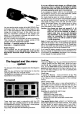
The Rserve Battery $ctem Tn nsm itf-r;r co ntrcI testrhgl withdrawthe batterycradleJromthe transmittercase, which is now tacingyou. Pull it upwardscaretully, holdingit at bothends(seeFig.42). The ReserveBatterySystem Manycar drivers,despitehavinga largelueltankand an accuratefuelgauge,carrya reservefuelcan in theircar: gettingstuckwith an emptytank is unpleasant, and can be dangerous.
your yoursell Fromthistimeon pleasebe sureto slow-charge onelasttime.Convince Nowcheckeverything as oftenas possible,so that you can be that the ribbon cable cannot obstructthe stick transmitter and vou are done.Closethe transmitter.surethatthereservebatteryis fullycharged. mechanics. ControlTest"menu The"Transmitter mustbe installed Thisshouldtellyoutwothings. functions Alltheslidersandswitched particular lf they are installedthe 1. The aileronDual-Ratesswitchis connectedto "51". orientation.
Pleasenotethis differencebetweenthe transmitter controls and the other switches, as described above, It is quitedifficultto describethesechecks,but you willfindthattheyonlytakea momentto carryout! Fig.50 Fig.51 Accessories Relocatingor installingswitches The switchesand their locationon the standard Stick tops havebeenchosencarefullyto meetmost transmitter The transmitteris suppliedwith 3 pairs of stick tops: practical requirements. modellers' and long.
stickers in the Thefinaljob is to applytheself-adhesive Remove nextto theswitches. eachsticker deoressions pliers, or fine-nosed in turn,usinga pair of tweezers placeit in thedepression in theswitchpanel,andpress a sticker it downfirmly(Fig.54).lf we havenotprovided printedwithyourparticular application, usethe all-yelwitha felttippen. lowstickers andwntetheinscription Fig.54 Frg.55 Fig.
Threeturthertips on this subiect. the names 1. In the exampleaboveyou could use "CORT-T11"insteadol "CORTINAI',"CORT-NF2" and "CORT-HS3"insteadof insteadof "CORTINA2" "CORT|NA3". In this caseTL standsfor tow launch, NF for normalflight,and HS for high speed.The nameswillthenremindyouof whichlistserveswhich purpose. Thef inalnumbersmustremain;buttheyare on theirown. notveryinlormative 2. lI youchangememoriesin the "normal"waytrom pleasecheckthatthe MemorySwitchis in the keypad, "basic" position.
The mainapplicationof "Sl" is in conjunctlonwith the transmittercontroloptions"FlX-1"and " FIX-2'. A furtherexamplewill makeeveMhingclear:"campositions". flapswith2 switchable ber-changing We will assumethattransmitter controlE is assigned to the "FLAP" function.Move to the "CONTROL OPTIONS"menu,and from thereto "CONTROLE: FLAP". Pressthe N key,and leaf throughto the "FlX-l" ootion.
Move to the "COPY MEMORY"menu, then to " MODE:EXPORT". Activate the sourcememoryusing the Sl key. The displayshouldlook like this, with the memory 06Jlashing: number rf'lü['E : E:":FüFtT r F F l t 'u' 1t :. F i E I T H Twofurtherpoints: 1. ll you shouldwish to interruptan import,export, copyor deleteprocessatteryou havestarted,simply Thedatain the model off briefly. switchthetransmitter willthenbe unchanged. memories is possiblebetweenall 2.
The switch harness This is pluggedintosocket" 8". The switchincorporatedin theharnessis usedto turnthewholereceiving in syslemon andotf.Theswitchitselfcanbe installed side. the model'sfuselage Switch harnessesare availablein severalforms; pleasereferto the main MULTIPLEX cataloguefor details.Some versionsare fitted with a separate On the switch socketfor chargingthe receiverbattery. harnesssuppliedwiththe set (OrderNo.I 5100)the chargesocketis integralwiththe switchcasing.
lf Extensionleadwith separationfilter and measurements. basedon our own experience your systempassesthis test,you can be sureyou are (60cm:OrderNo.I5082 120cm:OrderNo.I5083) Extensionlead set with separationfilter on thesafeside. (max.2 m: OrderNo.I5138) yourtransmitter aeriallully. 1. Collapse This is a kit which can be usedto connectservos 2. Ask an assistantto hold your modelabout1 m which arebuiltintowingsor otherpartsof the model. abovetheground. 3.
o Avoidplacingmechanical stresson thepowerleads andon thecellsthemselves. . Replace in goodtime. oldbatteries . NC packs fall into the categoryof dangerous Don'tjust of properly. waste,andmustbe disposed chuckthemin the rubbishbin! Storingbatteries for a long period, 11you do not use your transmitter points: takespecialnoteof thefollowing Stateof charge Experience showsthatNCpacksshouldbestoredin a (empty)state. discharged Self-discharge of theirchargeperdayunder NC packsloseabout10lo i.e.
to set Dividingthe flaperonintotwo makesit possible tlap up the functionsol aileronand camber-changing on terms,particularly in aerodynamic moreefficiently and improved wings(betterlift distribution long-span aileronresponse).
in largespan whichcan be verynoticeable ot efficiency, Diffierential: gliders. model intended to Termusedlor unequalaileronmovements, compensatefor the " negative"roll effect,otherwise Unequalaileronmo/emenb(muchmoreup movement knownas adverseyaw. or eveneliminate thando!\,n) canreducethiseffectgreatly, lf aileronsmovean equalamountup and down,the it altogether.
"CPM" control system(HEADMlx): for CollectivePitchlvlixing.The controlsigAbbreviation nalsfor collectivepitch,pitch-axisand roll-axisare electronically"composed"and sentto the servos.Between servos and swashplatethere are no mixer leversor similar mechanics,so mechanicalcomplexityis minimised.