
Operation Manual


Example
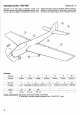
model:
'B,K117"
ExamDle of a
helicoDter with
"CPM"
swashplate
control
system.
The
swashplate
is controlled directly
by 3 ser-
vos, arranged
at
120
degrees
to each other,
which
pro-
vide collective
pitch, pitch-axis
and
roll-axis
control.
Three servos
are used,
in
conjunction
with the
"HEAD-MlX"
mixer. The throttle
is assigned to
Note:
Phase affects all rotor
head
servos
equally. Before
you
change the Geometry settings,
be sure to set up the collec-
tive
pitch
inDuts and check
that thev are correct,
Summary:
Memory No.: 15
"THROTTLE"
('DYNIHR.'is
an
alternative).
A
"sup-
pressible" gyro
is
assumed,
which can be switched
be-
tween minimum
and maximum effect
by means of
switched control
H.
"Flare"
mixing can be achieved by
unequal
collective
pitch
inputs to the
"centre"
and
"out-
board"
servos.
Channel
controls
Throttle
Servo
No
Function
Ro/Co/Pi Ro/Co/Pi
Ro/Co/Pi
Throttle
HEAD-MIX
HEAD-MIX
HEAD-MIX
1st inp.
ROLL
ROLL
PITCH
THROTTLE
YAW
2nd
inp.
PITCH
PITCH COLLECT.
coLLEgr.
3rd
inp.
coLLECr.
coLLEgr.
4f5I
Yaw
Gyro
Mixture
TAIL ROT
GYRO
MIXTURE
r 4th input: Geometry
sth
input:
Phase
Switches:
51
-
Dual Rates,
roll; 52
-
Dual Rates
pitch;
53
-
auto-rotation;
55
-
direct
throttle
Notes:
Switch
control
H must be fitted
(On/Off
switch,
3-core
lead)
3-Doint
throttle
curve used.
Piich
input value
for
"centre
servo"
twice as
great
as for
"outboard
servos"
(assuming
120 degree
arrangement)
Collective
pitch
input same
for all three servos
Possible
modif
ications: s-point
throttle
curve
Gyro
not used
(different
type
of
gyro)
24