
Operation Manual


Are
you
beginning
to
feel
at
home with the system?
The servo
travel
which
corresponds
to
moving the
stick
to
the left
is
selected
and then adiusted
by
"stick
|eft".
The servo
travel
which
corresponds
to
moving the
stick
to the right
is
selected
and then
adiusted by
"stick
right".
lf
you
now
move the stick to
right
and
then
left
you
will
see
that
the travel value alternates
between 80
and
900/o.
The
prefix
in front of the
travel value shown
is normally
irrelevant when adjusting
servo travel
(there
is an ex-
ception: see
below); it shows
whether the servo's
whole
travel
is reversed; see also
page
28:
"Servo
reversing".
Leave the Servo
adjustment menu by
pressing
the
E)
key.
Now
a few more
points:
It
makes no ditference
how far
you
move the sticks
when making these
adjustments;
the only
important
ooint
is
the direction
in which the arrow taces.
lf it is not
iikely
to confuse
you, you
can
move
the
corresponding
trim slider
instead, and
leave the stick at centre.
The same applies
to all servos/control
functions. For
functions
which correspond to
forward/back stick
move-
ments, the right and
left arrows are
replaced by up
and
down arrows.
All
percentage
values refer to the
normal nominal
travel
of the servo concerned;
this
is usually
45
degrees
(aF
though
there are exceptions).
There
is no reason
why
you
should
not set extreme
travel
adjustments.
For instance,
in
the
example above
you
could
set the
left travel of the stick
to zero;
in that
case the servo
would
not move at all
when
you
move
the stick
in that direction.
You can even
set the travel
to
less than
zero,
i.e.
a
negative
value,
by
simply
pressing
the
n key.
The servo will
now move to the
right when
you
move
the stick to the
left, as well as
when
you
move
it to
the right
(as
you
have not changed
that side
of neu-
tral). Quite
why
you
might want to
do that
is
beyond
us
iust at
the moment!
Caution
-
a trap
for the unwary!
Please don't
set the
travel to zero on both
sides ol
neutral. The
result would
be
that the servo
does not
move at all.
lf
you
do
this for
some
reason, but then
forget that
you
have done
it,
you
will have an apparently
nonJunctioning
channel,
which will drive
you
uncomfortably
close
to the edge
of
insanity . . .
The other side
of this coin:
if
you get
"nothing
at
all" at
one receiver
output, check
first whether
you
have set
the servo
travel to zero by
mistake!
Servo
travel can also be
set to more than
usual: a sel-
ting of up to
1100/0 is
possible.
we
do
not recommend
using this
lacility excessively,
as, with certain
types of
servo
(linear
output servos
in
particular)
you
run the
risk
of
jamming
the
mechanics
mechanically.
You might
also like to bear
in mind that
an output travel
of more
than 45 degrees usually
provides
very little extra
move-
ment, due to the
geometry
of standard
mechanical
link-
ages.
How to
limit servo
travel
With
mixed functions it can
occur that the
sum of mixer
inputs exceeds
the
maximum travel
of the control sur'
face
(mechanical
limits), e.g.
mixed ailerons/flaps
with
flaps at the
launch
position.
Here the
variable servo
travel
limit
"LlMlT"
can
help.
lf
you
are still at
the
"Adjust
SERVO"
menu,
press
the
"LlMlT"
key and
you
will
see
the
following:
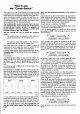
r::EFi.
1
:
LIIiIT:
H I LEFIÜI'I
+
1ül:tilr
Now
you
can set
the maximum
possible
travel
for each
servo
separately,
for each direction.
Return
to the Status display
with
@ @ El.
Full travel
is resumed
when
you
erase
a model
memory.
Caution:
when data
is transferred
between
two trans-
mitters
the LIMIT
values are
not transferred.
How
to
make travel
inputs switchable
In the
"swlTcH"
menu, which
you
reach
with the key
sequence @ZZ
(starting
trom the
basic display),
all
travel
inouts for the servos
can be switched
ON/OFF
or
rendered
switchable.
By
"switchable"
we
mean that a
physical
switch
is assigned to
that travel
input.
Let's
look at an
example: switch
to memory
07 SALTO,
then
move
to the
"SWITCH"
menu
(E)ZZ).
The dis-
play
will
look something
like this:
rSEFI.
1
:
FLHFEFIIH
rtl
l LEE::
Ul'l
r
lf this
is not
the case,
press
Z
and
select servo
1 with
the
EIE
keys.
Now
press
51,
and
AlLeron
will llash.
switch
between
the two
inputs
Alleron
servo
1
by
pressing
the
El
key.
30
You
and
can
now
FLAP
tor
At bottom
right
you
will
see
that the
aileron
input is al-
wavs switched
on,
while the
FLAP input can
be
switched
in
and
out using
the 53 switch.
In
practice
the system
works as
follows:
1.
Move to the
"SWITCH"
menu.
2.
Z:
Select servo.
3.
fl:
Select
input
El:
Switch ON/OFF
with
the
El
key.
Repeat until
you
have covered all
the inputs.
4. Return
to
ooint
2. and
continue until
all servos
have been
covered.
Another
trap tor the unwary:
lf
servos
which are
controlled
by mixed
functions ap-
pear
not to
respond to
the transmitter
controls
in the
way
you
intended,
then
you
may find that
the inputs
have been switched
OFF completely
in the
"SWITCH"
menu.
The second
possibility
is that the
inputs have
been assigned
to a
physical
switch
which
is in the
wrong
position.