
Operation Manual


The
"ldle
Trim" option
This option
is only available
for the
"THROTTLE"
con-
trol
function
(or
THROTTLE-2).
lts effect is that
the throt-
tle stick
trim slider
is only effective
when the stick is at
its
"idle"
position.
lts effect
is
steadily
reduced towards
the centre
position
of the stick.
In the whole of the
full-
throttle
"half"
of
the
stick
arc
(especially
at
the
"full
throttle"
end-point)
the trim slider has
no
effect.
The
practical
advantage
oJ this option
is that
you
can
adjust the
idle setting of the
carburettor
without
aftec!
ing its
lull-throttle
position.
Selecting
and adjusting
this option
is
the same
as for
the other options already
described.
Adiustment
range:
0
0/o
in the display:
the
"throttle"
trim slider
has no
effect.
100 % in the display:
the
"throttle"
trim slider
adjusts
the idle
position
within the
whole of
one halt of the stick
arc.
In
practice (special
cases excepted) a
value of 20 to
300/0
is a sensible sefting.
One
further note:
Normally the
idle
position
of the throttle stick
is
"stick
back". lf
you
want
it
the
other way round
(e.9.
for
a
heli-
copter),
press
the
y
key once at the adjustment
stage.
This reverses the entire stick
function; idle is then
"for-
ward". This is
indicated in the display by a
minus
sign
(-)
in lront of the set value, instead of a
plus
sign
(+).
lf
the
servo
then rotates
in
the
wrong direction,
reverse it
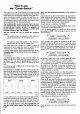
Fis.25
as described on
page
28.
Stick
ldle trim
The
"Differential"
option
This option
is only available if a transmitter control
has
been assigned
to the control
function
"AILERON"
at
the
"Assigning"
stage, and
if
at
least two servos have
been
assigned
to
"aileron".
In all other cases
differential
makes
no
sense,
or can be
replaced
by
the option
"Asymmetrical
travel adjustment".
Fig. 26
To explain
how this works,
we will
take another
example.
The
transmitter controls and
servos have been as-
signed
as follows:
Transmitter control
A
=
AILERON; servo
1=
ATLERON; servo 5
=
AILERON
Starting
from the Status Display,
move to the
"Transmi!
ter Control
Adjustment"
menu. Press the
N
key
and
leaf through
with
El
until
you
see
"DlFFER."
in the dis-
play,
f lashing:
rH:
I I
LEF: ['I FFEF'I
HItit'l1'lETF:
! +Ir:rlir
It is vital that the servos
are assigned correctly, oth-
erwise the differential
movements
will not be correct
(see page
26).
Press the
Z
key; the value at bottom
right will flash.
You can
now
set
the degree of difterential
you
require
using the
E)
and
E
keys.
The f igures mean:
0
0/o -
no ditferential; same
movement up and down
lor both servos.
5O
o/o -
the
"down"
movement
is
only
half as large
as the
"
uD"
movement.
1oo
o/o -
maximum ditferential: each aileron
moves uo,
but does not move down at
all.
You don't need to
worry about anything else
when set-
ting up ditferential.
The differentiated
control signals are
sent
to the two servos automatically.
When setting the degree ot
difterential
you
can
"re-
verse" the differential
with the
El
key.
You will
find that it is
possible
to set up differential
ailerons correctly,
regardless of
your
installation, by us-
ing this option
in conjunction
with reversing one or both
servos
(see page
28). We
cannot
give general guide-
lines, however, as
there are so
many
possible
variations
in model design
and radio installation.
One
more tip
(which
also applies
to other adjustments):
It is
sometimes
easier and
quicker
to find exactly the
right settings by carrying
out
"
in flight" adjustments.
This is very
easy
using the Digi-Adjustor,
which is avail-
able
as an accessory:
Before
starting
a flight,
move to the appropriate menu
as
already described, and select
"Adjust
Value"
as de-
scribed above; but
this time don't leave the
menu!
t*=
\\
50
0,6
1(
\'.\-
^
\so&
\'.{;
'(
Difter.ntial
35