
Operation Manual


The swashplate control
system
Here
we
can't
avoid
getting
a
little deeper
into the tech-
nology,
as there are several
different rotor
head control
systems,
or designs,
which differ
widely from each
other.
In fact they all do the same
job:
they
provide
con-
trol of collective
pitch,
roll-axis and
pitch-axis.
However,
the
different systems
make
quite
different
demands on
the
number of servos
and how they are used.
For this
reason we
present
here
a brief
description
of the
three most important systems,
and
the
assignments
required
for
each:
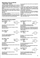
1. The
"classical"
fixed swashplate
move along
the axis of the
rotor shatt;
it can only tilt.
Collective
pitch
control
is
via
a oushrod
which runs
inside the
hollow rotor
shaft,
or in a
groove
in the
rotor shaft. Collective
and
cyclic
pitch
are
mixed
mechanically,
"
higher
up",
at the
rotor.
The
swash-
plate
is controlled by two
servos,
set at 90 degrees
to each other.
Fio.33
There are therefore
three servos
for
collective
pitch,
roll-
axis and
pitch-
axis,
which have entirely separale
func-
tions.
Servo
No. 1 controls
ROLL-axis
Servo
No. 2 controls
PITCH-axis
Servo
No. 5 controls COLLECTIVE
PITCH
lf
you
wish,
you
can mix in the
pitch-axis
input to collec-
tive
pitch
at a later stage,
if
you
find it necessary
(tor
the
transition
from cruise
to hoveo. To achieve
this, assign
"
FLARE" to the Ditch-axis
servo.
Please
note that if
you
change the
assignment, all
the
previous pitch-axis
servo adjustments
will be lost.
2. The
"CPM"
swashplate
CPM
stands
tor
"Collective
Pitch Mixing".
This type of
linkage
is to some extent the
opposite of the
fixed
swashDlate.
In this case
the swashplate
is Jree to move
along
the rotor shaft
in the axial direction.
Moving it axi-
ally
produces
collective
pitch
control; tilting
it
produces
cyclic
pitch
control.
Three servos
are again
required, but in this case
all
three act on
the swashplate.
This arrangement
is known
as a 3-point
linkage.
However, it is
possible
to use more
servos
to control
the swashplate.
A 4-point
linkage
presents
no
problem
to the transmitter.
You could even
"distribute"
5 or
more servos around
the
rotor head, should a
helicopter
with these features
ever
come onto the
market.
There are
two different
methods of arranging
these
three servos:
the
"go-degree
arrangement"
and the
"120-degree
arrangement"
:
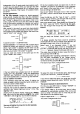
The
90-degree
arrangement
is the simpler
one.
All three servos
must tirst be assigned
an equal
part
of
the ooLLECTIVE
PITCH signal;
the result
is that the
swashDlate
rises and
falls
evenlv
when the collective
54
Fig.34
pitch
control
is operated. For roll control
only the two
outer servos are operated,
in this case
in opposite
directions.
Finally the central
servo alone
provides
pitch-axis
control.
The 120-degree arrangement distributes
the
loads to
the servos
more evenly.
For collective
pitch
control all three servos
again
receive an equal
part
of the COLLECTIVE
PITCH sig-
nal. For roll control, once again,
only the two outer ser-
vos are operated,
in opposite directions.
For
pitch-axis
control.
however. all three servos
must work: the two
outer
ones work together, but
in the opposite direction
to the central one.
Even this is not the end of
the matter: the servo
move-
ments must be different.
The two outer servos,
when
required to
produce
a
pitch-axis
movement, deflect by
the same amount.
The central one
has to move twice as
far.
The same
"HEAD-MIX"
mixer
is
used
for controlling
the servos
in both versions ot
the CPM rotor
head:
geometry
collective
pitch
roll-axis
pilch-axis
phase
This mixer offers
the facility to
feed
adjustable
COLLEC-
TIVE
PITCH, PITCH-AXIS and
ROLL-AXIS
inputs to
each servo.
Any
input which is not
required
-
e.g.
ROLL for the central
servo
-
is
simply
set to zero
(00/o),
i.e. switched
otf.
The servo assignment
is simple:
Servo
No. 1
controls
HEAD-MlX,
Servo
No. 2 controls HEAD-MlX,
Servo
No. 5 controls
HEAD-MlX.
Naturally,
you
still
have to set the
magnitude and
direction of the three
inputs.
As
an
example to
help
you
remember, the display
will
look like this
(servo
No. 2):
H5:,ItjH :;EFjtJu
:
I
TLt HEHtt-l'lI
lir
The 4-point linkage
is, in
practice,
a
go-degree
arrange-
ment
with 2
oitch-
axis servos.
Your PROFI mc 3010
makes everything
very simple.
You assign
'HEAD-MIX"
to, say, servos 3
to 6.
You will
find the necessary adjustments
on
page
62.
I
AEargem.nt
9d
",1
U
,
"*:*.
l.
ffi-'x
(+
clllocllr. lro|]l
J
S€rw 5
tor
n
ro
r.0ü!) Call€ciiv!
picn