
Operation Manual


3.
The
"Heim"
$t ashplate
This swasholate
is
also
free
to
move axially,
and collec-
*
tive
pitch
is achieved by
this
movement.
However, it
is only
controlled
directly
by
two
(outboard)
servos;
when they
move in the
same direction
the
result is
a collective
pitch
move-
ment; when they
move in
opposite
directions
the
result
is a roll movement.
A bellcrank
is
provided
for
Ditch-axis control.
and this
is operated
by the
pitch-
axis
servo,
which
is
mounted at
righlangles to
the rotor shatt.
The bellcrank
"tloats",
and
thus moves
up
and down
with the swashplate.
The bellcrank
"de-
couples"
pitch-axis
control
from collective
pitch.
By an
ingenious
design of the
floating bellcrank
pivot
"flare"
mixing is achieved
automatically, so
no special
"flare"
mixer is needed.
A soecial
"HEIMHEAD"
mixer is
provided
for the two
"coilective
oitch/roll"
servos.
collective
pitch
roll-axis
Servo assignment
is as Jollows:
Servo
No. 1 controls
HEIMHEAD
Servo
No.
5 controls
HEIMHEAD
Servo
No. 2 controls
PITCH-AXIS
Transmitter
control options
for helicopter control
systems
The transmitter
oflers a series ol options
tor helicopter
control
systems, exactly
like the fixed-wing
control sys-
tems,
which
you
can
"activate",
and adjust,
when
you
need
them.
ll the term
"transmitter
control
options"
is not clear,
please
turn back to
page
32
and read that section.
To some extent
these ootions are
identical to
those tor
fixed-wing
models;
however, some of them
are specific
to helicopters.
The
helicopter-specific
options are explained
in the
fol-
lowing section.
Here
again,
you
are free to
make use of as
many of
these
options
-
or as
few of them
-
as
you
wish.
The
following options are available:
ODtion
Transmitter control
Dual Rate
PITCH,
ROLL, YAW
(tail
rotol)
Exponential
COLL.
PITCH, PITCH,
ROLL, YAW
Travel adj., both
s. PITCH, ROLL,
YAw, COLL. PITCH.
Centre adjust
PITCH, ROLL, YAW MIXTURE,
COLL. PITCH*-
ldle
THROTTLE
Fixed
value THROTTLE
Throttle curve
collEgrlvE
PITCH
Direc
hrot
e
coLLECrlvEPITCH
Gyro ON/OFF
GYRO
'"Coll€ctive
pitch
maximum" and
"coll.
pitch
minimum"
in helicopter terminology.
"
"Collective
pitch-hover"
in helicopier terminology.
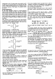
The
"collective
pitch
curve"
The term
"collective
pitch
curve"
refers to the
relation-
ship between
the
position
of the collective
pitch
stick
and
the actual angle
of collective
pitch.
Please
refer to
Fio. 36
here:
Fig.36
When the collective oitch
stick is set to
"Centre",
the
helicopter
is required to
hover: this
is the
"Hover
Point"
(HP).
The corresponding
angle ol
rotor blade
pitch
is
usually
stated by
the helicopter
manufacturer, and
is
usually
in the range +2lo
+4 degrees;
+3 degrees
is
a
good
starting
point
for
your
own experiments.
At the
"maximum
collective
pitch"
stick
position
the
rotor blades
are set to the
maximum
pitch
angle for
nor-
mal flying; here abbreviated
to
"P+".
lts actual
value is
best
discovered
in
practical
flight testing,
as it varies
according
to the motor
power
available
(see
below).
At the
"
bottom
end"
is
the
"minimum
collective
pitch"
position
-
point
"P-".
This setting
is not critical and
varies according
to the
model and the
pilot.
lt is best
for
beginners
to stick
to the helicopter
manulacturer's
rec-
ommendation
here; experts
will have their
own ideas.
You can
adjust all
three
points
independently of each
other.
In tact, these
adjustments are
no different
from
centre
adjustment
and separate
travel adjustment
of the
collective
pitch
transmitter control,
and
you
will find
them in the
menu under these
terms. So:
move to the
"Adiust
transmitter
controls"
menu;
leaf through to the
COLLECIIVE
PITCH
control.
Set
the hover
point (HP)
with the
"Centre"
ootion. and
collective
pitch
maximum
and
minimum with the
option
"Asymmetrical
Travel".
Note:
As
collective
pitch
is always adjusted
in conjunc-
tion with the
"throttle
curve",
we will have
to come back
to this subject
in due course.
Colleclive
pitch
servo
SP
Collective
pilch
slick
o