
Operation Manual


wing
models.
lt
you
wish to
do this,
move to the
"Adiusj
transmitter
controls"
menu
and select
the
THROTTLE
control.
You can
now select
the
"ldle"
option and
adjust
the throttle oosition
Jor the
"idle"
position
of the slider
and switch
between
forward
and back
(2,
then
tr)'
Switching
the
idle
position
is indicated
by the
prefix.
Auto-rotation
One switch
can
be dedicated
as an
auto-rotation
selec-
tor.
When
it is switched
to auto-rotation,
the transmitter
does
two things:
1.
lt
sets
the throttle
to a
pre-selected
setting
(idle
lor
practising;
OFF
tor competition
work).
2.
Any limit set
on collective
pitch
travel at
the
transmitter
control end
is lifted
(to
make f ull col-
lective
pitch
movement
available).
lf
you
do
not
require this
feature, adjust
collective
pitch
travel
at
the servo
only.
You
will now
probably
be
thinking:
'what
about
the tail
rotor?"
Normally, because
main rotor
power
torque
is
absent
during
auto-rotation,
the
mixing of collective
oilch to
tail rotor
has to be
removed.
The PROFI
mc 3010
offers
you
a very simple
and
elegant
feature:
you
simply
need to
move to the
"Servo
adiustment"
menu, select
"TAILROT",
and select
the
"doLLECIIVE
PITCH" input as
switchable,
then
assign
the
same switch
as for auto-rotation.
lf, for exam-
ple, you
select
the switch
"55"
for auto'
rotation
(we're
just'coming
to that!),
then
make the coLLEcTlvE
PITCH
input to
"TAILROT"
also switchable
by
"S5".
There
is a further
possible
refinement
to this;
please
read the
note at the
end ol this
section.
What
you
have
to adiust:
There
are two
points
to
remember
here:
1.
Set
the
"auto-rotation
throttle" to
"Fixed
Value"
2. Assign
the
"auto-rotation"
switch.
This should
tell
you
where
you
will
find auto-rotation:
it
is
"
hidden" under
THROTTLE.
To do
this,
move again
to the
"Transmitter
Optionsl
menu;
then on
to the
THROTTLE control.
Press the
N
key and
select
the
"FlX-1"
(fixed
value) option
with
the
E
keY.
You
will see
the following
display:
rE:
THHr:rT
FIll-1r
r[rFF
E]':r
First:
"auto-rotation
throttle"
Press the
Z
key
followed by
El,
then set
the desired
throttle
setting
in the usual
way with
the
El
or
E
keys,
or
the Digi-Adjustor;
0
-
100/o
is
a
good
starting
point.
Now define
the auto-rotation
switch:
Press the
Sl
key, then
select the
switch
you
want to use,
using
the
E
and
E
keys, as
usual;
for example
the
switch
"S5".
That's all there
is to
it.
Now to the
actual
problem.
For auto-rotation
the
collective
pitch
input
needs to be
switched
ofi.
This
is
the
procedure:
move to the
'SWITCH
SERVO"
menu and assign
the
"COLLEC'
TIVE PITCH"
inout to the
auto-rotation
switch 55.
Switch
the'INPUT'to
"F|XED
VALUE" and assign
the
switch
55
to that too, but
working
in the opposite
direc-
tion.
To
do
this,
with the input
field still active
(flashing),
oress E
.
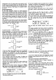
Sample
display,
memory
15, BK 117:
r5EFI.
5: TH
I LF;ÜT.
r[:[rLL,
:
!,5+.
r
r5EFt.
5:
Trl I LF:r:rT.
rFiiiEtl:
-i5'+.+
r
The net etfect
is that by
operating
the switch
S5
you
close
the throttle,
set collective
pitch
otf, set a
(variable)
fixed value on,
and switch
to a second
collective
pitch
travel.
The travels
are
adjusted
in the SERVO
TRAVEL &
REVERSE
menu.
Gyro
suppression
"Suppression"
means
reducing
or eliminating
the
damping
effect
of the
gyro
when the
pilot
wishes
to
override
it. This is essential,
as
the
gyro
is only intended
to
reduce
unwanted
flight
movements due
to
gusts
etc.,
and
not to counteract
deliberate
efforts
on the
part
of
the
pilot.
There are
three basic
types ot
gyro:
1.
Gyros
with
no
special
facilities
tor
allowing
control
from the
transmitter.
Some
ol these
gyros
also have
a
"suppression"
effect,
which
is derived
from the
yaw
control signal
emanating
from
the
receiver.
These
gyros
have only
one connec-
tion
to
the receiver.
lf
you
are
using
this type
of
gyro,
you
do
not need
to assign
"GYRO'
to a transmitter
con'
irol
nor a servo.
There
is nothing else
to say
on this type
ol device.
5ö
2. Gyros
whose
sensitivity
can be altered
or switched
otf trom
the transmitter.
For this
type ot
gyro
a switched
transmitter
control
is
needed
(e.9.
channel
"G"),
which
is then assigned
to
the
"GYRO"
function;
you
will also
need a
"servo"
out-
put
by the
name
of
"GYRO".
This
is where the sensitiv-
ity sr,tiitcn
input
from the
gyro
is
connected.
"Automatic
proportional
suppression"
is of
no relevance
here
"Gyro
suppression"
at the
'GYRO"
transmitter
control
is therefore
set
to
"OFF".
3.
Gyros
with
proportional
sensitivity,
adjustable
from
the
transmitter.
This is the
type of
gyro
with
which we are
primarily
con-
cerned
here.
To
control
the sensitivity
of the
gyro
a spe-
cial
signal
is derived
from the
YAW signal
in the trans-
mitter, and
this signal
is then
transmitted
to the
gyro
via
the servo
outout
"GYRO":
this is termed
"automatic
gyro
control"
or
"automatic
gyro
suppression".