
Operation Manual


ROYAL evo
Page 66
ule is to be stored outside the transmitter, it is
essential to protect it from dirt and damp, and al-
so from shock and vibration.
7.4.4. Changing the transmitter crystal
(HFM-4 module only)
The crystal should be pulled out of the RF module by its
plastic tag. First switch the transmitter OFF and remove
the RF module. When fitting a crystal ensure that it is
not mechanically stressed, and that the crystal pins are
not bent.
Use only MULTIPLEX transmitter crystals, designed for
the same frequency band as your RF module. We can-
not guarantee reliable operation otherwise. MULTIPLEX
transmitter crystals are enclosed in a translucent blue
plastic sleeve and are printed with the code letters “S”
or “Tx”.
! Crystals are extremely delicate components,
vulnerable to shock and vibration. They are one
of the crucial parts of your RC system, without
which reliable operation is not possible. For this
reason never drop them, subject them to me-
chanical load (by pushing them forcibly into the
crystal socket), and always store them carefully.
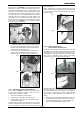
7.4.5. Changing the transmitter battery
1. Switch the transmitter OFF!
2. Pull the snap-latches of the two plastic battery
holders back towards the battery, and fold them up
(Fig. 1).
3. Remove the battery and disconnect the battery
connector from the main circuit board (Fig. 2).
Fig 1
Fig. 2
When installing the battery ensure that the battery lead
is correctly positioned, and cannot become jammed or
snagged when you close the case.
Note:
Model data is not lost when you change the battery.
7.4.6. Disabling the stick neutralisation system,
installing the spring for ratchet or friction op-
eration
The ROYALevo transmitter is supplied as standard with
two self-neutralising stick units. The stick neutralising
system can be disabled, and a stick ratchet spring or
friction mechanism can be activated quickly and easily
as follows:
Switch off the transmitter!
1. Locate the TORX screwdriver (in a clip below the
aerial guide sleeve, close to the screen) and use it to
rotate the TORX screw (1) of the stick neutralising
arm clockwise until the neutralisation is completely
disabled. Don’t unscrew it too far! The neutralising
arm must not be removed!
2. If the stick shall work with friction the spring must
be displaced. Tighten screw (2) fully and adjust the
strength of friction/ratchet with screw (3). The fur-
ther the screw is tightened, the greater the holding
force of the spring.
It is also possible to fit both springs if you wish. This
produces a hybrid ratchet / friction movement of the
stick which some pilots find they prefer.
7.4.7. Adjust the neutralising force
The neutralising force is adjustable for each of the four
stick axis separately. The illustration above shows,
where the screws are located. Turning clockwise the
screws (4) increases the neutralising force.
(4) neutralising
force for right/left
stick moves
(4) neutralising
force for
forw./backw
s
tick moves
(1) disable
neutralising
(3) strength for
ratchet/friction
(2) Spring position for
friction or ratchet