PARTS AND OPERATION MANUAL OPERATION AND PARTS MANUAL WHISPERWATTTM SERIES MODEL DCA-400SSV 60 Hz GENERATOR PARTS LIST NO. C3871301004 Revision #0 (04/19/06) THIS MANUAL MUST ACCOMPANY THE EQUIPMENT AT ALL TIMES.
PAGE 2 — DCA-400SSV— OPERATION AND PARTS MANUAL — REV.
HERE'S HOW TO GET HELP PLEASE HAVE THE MODEL AND SERIAL NUMBER ON-HAND WHEN CALLING MQ POWER CORPORATE OFFICE 18910 Wilmington Ave. 800-421-1244 Carson, CA 90746 FAX: 310-632-2656 Email: mqpower@multiquip.com Internet: www.mqpower.com PARTS DEPARTMENT 800-427-1244 FAX: 800-672-7877 310-537-3700 FAX: 310-637-3284 SERVICE DEPARTMENT 800-835-2551 FAX: 310-638-8046 310-537-3700 TECHNICAL ASSISTANCE 800-835-2551 FAX: 310-638-8046 WARRANTY DEPARTMENT 800-835-2551, EXT. 279 FAX: 310-638-8046 310-537-3700, EXT.
TABLE OF CONTENTS MQ POWER DCA-400SSV WHISPER WATTTM GENERATOR WHISPERW California Proposition 65 Warning ..................................... 2 Here's How To Get Help .................................................... 3 Table Of Contents ............................................................. 4 Parts Ordering Procedures ............................................... 5 Specifications ................................................................... 6 Dimensions (Top, Side, Front) ...............
PARTS ORDERING PROCEDURES When ordering parts, please supply the following information: ❒ ❒ ❒ ❒ ❒ ❒ ❒ Dealer account number Dealer name and address Shipping address (if different than billing address) Return fax number Applicable model number Quantity, part number and description of each part Specify preferred method of shipment: ✓ FedEx or UPS Ground Note: Unless otherwise indicated by customer, all ✓ FedEx or UPS Second Day or Third Day orders are treated as “Standard Orders”, and will ✓ FedEx or UPS Nex
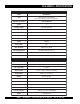
DCA-400SSV— SPECIFICATIONS Table 1. Generator Specifications Model DCA-400SSV Type Revolving field, self ventilated, open protected type synchronous generator Armature Connection Star with Neutral P ha s e 3 Standby Output 440 KVA (352 KW) Prime Output 400 KVA (320 KW) Voltage — 1Ø 120, 127, 139, 240, 254, and 277V Voltage — 3Ø 208, 220, 240, 416, 440, and 480V Frequency 60 Hz Speed 1800 r pm Power Factor 0.8 Aux. AC Power Single Phase, 60 Hz Aux. Voltage/Output 120 VAC/ 4.8 Kw (2.
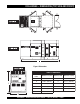
DCA-400SSV— DIMENSIONS (TOP, SIDE AND FRONT) Figure 1. Dimensions TABLE 3. DIMENSIONS Reference Letter Dimension in. (mm.) Reference Letter Dimension in. (mm.) A 41.73 in. (1,060 mm.) G 19.30 in. (490 mm.) B 19.30 in. (490 mm.) H 41.73 in. (1,060 mm.) C 31.88 in. (810 mm.) I 165.3 in. (4,200 mm.) D 31.69 in. (805 mm.) J 82.67 in. (2,100 mm.) E 18.11 in. (460 mm.) K 55.11 in. (1,400 mm.) F 31.88 in. (810 mm.) 1 DCA-400SSV— OPERATION AND PARTS MANUAL — REV.
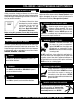
DCA-400SSV— SAFETY MESSAGE ALERT SYMBOLS FOR YOUR SAFETY AND THE SAFETY OF OTHERS! Safety precautions should be followed at all times when operating this equipment. Failure to read and understand the Safety Messages and Operating Instructions could result in injury to yourself and others. NOTE This Owner's Manual has been developed to provide complete instructions for the safe and efficient operation of the MQ Power Model DCA-400SSV Whisperwatt™ Generator.
DCA-400SSV— SAFETY MESSAGE ALERT SYMBOLS WARNING - ROTATING PARTS NEVER operate equipment with covers, or guards removed. Keep fingers, hands, hair and clothing away from all moving parts to prevent injury. CAUTION - ACCIDENTAL STARTING ALWAYS place the Engine ON/OFF switch in the OFF position and remove the ignition key when the pump is not in use. CAUTION - OVER-SPEED CONDITIONS NEVER tamper with the factory settings of the engine governor or settings.
DCA-400SSV— RULES FOR SAFE OPERATION DANGER - READ THIS MANUAL! Failure to follow instructions in this manual may lead to serious injury or even DEATH! This equipment is to be operated by trained and qualified personnel only! This equipment is for industrial use only. The following safety guidelines should always be used when operating the DCA-400SSVWhisperwatt™ AC Generator. General Safety: ■ DO NOT operate or service this equipment before reading this entire manual.
DCA-400SSV— RULES FOR SAFE OPERATION Generator Grounding To guard against electrical shock and possible damage to the equipment, it is important to provide a good EARTH ground. Article 250 (Grounding) of the National Electrical Code (NEC) provides guide lines for proper grounding and specifies that the cable ground shall be connected to the grounding system of the building as close to the point of cable entry as practical.
DCA-400SSV— RULES FOR SAFE OPERATION Maintenance Safety ■ The electrical voltage required to operate the generator can cause severe injury or even death through physical contact with live circuits. Turn all circuit breakers OFF before performing maintenance on the generator. ■ NEVER lubricate components or attempt service on a running machine. ■ ALWAYS disconnect the NEGATIVE battery terminal before performing service on the generator.
DCA-400SSV— RULES FOR SAFE OPERATION Towing & Transporting Safety ■ The maximum speed for highway towing is 55 MPH unless posted otherwise. Recommended off-road towing To reduce the possibility of an accident while transporting is not to exceed 15 MPH or less depending on type of the generator on public roads, always make sure the trailer terrain.
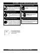
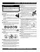
DCA-400SSV— GENERATOR DECALS The DCA-400SSVgenerator is equipped with a number of safety decals (Figures 2 & 3). These decals are provided for operator safety and maintenance information. The illustration below and on the preceding page show the decals as they appear on the machine. Should any of these decals become unreadable, replacements can be obtained from your dealer. Figure 2. Generator Decals PAGE 14 — DCA-400SSV— OPERATION AND PARTS MANUAL — REV.
DCA-400SSV— GENERATOR DECALS Figure 3. Generator Decals (Cont inued) DCA-400SSV— OPERATION AND PARTS MANUAL — REV.
DCA-400SSV— INSTALLATION Figure 4. Typical Generator Grounding Application PAGE 16 — DCA-400SSV— OPERATION AND PARTS MANUAL — REV.
DCA-400SSV— INSTALLATION Outdoor Installation Generator Grounding Install the generator in a area that is free of debris, bystanders, and overhead obstructions. Make sure the generator is on secure level ground so that it cannot slide or shift around. Also install the generator in a manner so that the exhaust will not be discharged in the direction of nearby homes. The installation site must be relatively free from moisture and dust. All electrical equipment should be protected from excessive moisture.
DCA-400SSV— GENERAL INFORMATION DCA-400SSVWhisperwatt™ Series Familiarization Generator The MQ Power Model DCA-400SSVis a 320 kW generator (Figure 5) that is designed as a high quality portable (requires a trailer for transport) power source for telecom sites, lighting facilities, power tools, submersible pumps and other industrial and construction machinery.
DCA-400SSV— MAJOR COMPONENTS Table 4. Generator Major Components ITEM NO. DESCRIPTION 1 Output Receptacles Assembly 2 Output Terminal Panel Assembly 3 Muffler Assembly 4 Air Filter Assembly 5 Fuel Tank Assembly 6 Engine and Radiator Assembly 7 Generator Assembly 8 Battery Assembly 9 Generator Control Panel Assembly 10 Circuit Breaker Assembly 11 Engine Operatingl Panel Assembly Figure 5. Major Components DCA-400SSV— OPERATION AND PARTS MANUAL — REV.
DCA-400SSV— GENERATOR CONTROL PANEL Figure 6. Generator Control Panel The definitions below describe the controls and functions of 8. the DCA-400SSVGenerator Control Panel (Figure 6). Panel Light Switch – When activated will turn on control panel light. Voltage Regulator Control – Allows ±15% manual adjustment of the generator’s output voltage. 1. Pilot Lamp – Indicates the 2. Panel Light – Normally used in dark areas or at night time. When activated, panel lights will illuminate. When 10.
DCA-400SSV— GENERATOR CONTROL PANEL Also the engine controller will shut down the engine in the event of low oil pressure, high coolant temperature, low coolant level, and loss of magnetic pickup. These conditions can be observed by monitoring the LED status indicators on the front of the controller module. A. MPEC Control Switch – This switch controls the running of the unit. If this switch is set to the OFF/RESET position, the unit will not run.
DCA-400SSV— ENGINE OPERATING PANEL Figure 7. Engine Operating Panel The definitions below describe the controls and functions of B. Low Oil Pressure Lamp – During normal the DCA-400SSVEngine Operating Panel (Figure 7). operation of the generator this lamp should remain OFF. When the Auto-OFF/Reset1. Tachometer – Indicates engine speed in RPM’s for 60 Manual switch is set to the “Manual” Hz operation.
NOTE PAGE 1 DCA-400SSV— OPERATION AND PARTS MANUAL — REV.
DCA-400SSV— OUTPUT TERMINAL PANEL FAMILIARIZATION Output Terminal Panel The Output Terminal Panel (Figure 8) shown below is located on the right-hand side (left from control panel) of the generator. Lift up on the cover to gain access to receptacles and terminal lugs.
DCA-400SSV— OUTPUT TERMINAL PANEL FAMILIARIZATION 120 VAC GFCI Receptacles There are two 120 VAC, 20 amp GFCI (Duplex Nema 5-20R) recepacles provided on the output terminal panel. These receptacles can be accessed in any voltage selector switch position. Each receptacle is protected by a 20 amp circuit breaker. These breakers are located directly above the GFCI receptacles.
DCA-400SSV— OUTPUT TERMINAL PANEL FAMILIARIZATION Connecting Loads Loads can be connected to the generator by the Ouput Terminal Lugs or the convienience receptacles (Figure 12). Make sure to read the operation manual before attempting to connect a load to the generator. To protect the output terminals from overload, a 3-pole, 1000A main circuit breaker is provided. Make sure to switch ALL circuit breakers to the OFF position prior to starting the engine.
DCA-400SSV— LOAD APPLICATION Single Phase Load Three Phase Load Always be sure to check the nameplate on the generator and equipment to insure the wattage, amperage, frequency, and voltage requirements are satisfactorily supplied by the generator for operating the equipment. When calculating the power requirements for 3-phase power use the following equation: Generally, the wattage listed on the nameplate of the equipment is its rated output.
DCA-400SSV — GENERATOR OUTPUTS Generator Amperage Generator Output Voltages A wide range of voltages are available to supply voltage for Tables 8 and 9 describe the generator’s current output capamany different applications. Voltages are selected by apply- bility for both 1Ø-phase and 3Ø phase applications. ing jumpers (6) to the voltage change-over board (Figure 14). Table 8.
DCA-400SSV— GENERATOR OUTPUTS/ GAUGE READING Maximum Amps Table 10 shows the maximum amps the generator can provide. DO NOT exceed the maximum amps as listed. Table 10. Generator Maximum Amps Model DCA-400SSV Rated Voltage Maximum Amps Single Phase 120 Volt 888.9 amps (4 wire) Single Phase 240 Volt 444.4 amps (4 wire) Three Phase 240 Volt 962.3 amps Three Phase 480 Volt 481.1 amps How to Read the Output Terminal Gauge.
DCA-400SSV— OUTPUT TERMINAL PANEL CONNECTIONS UVWO Terminal Output Voltages Various output voltages can be obtained using the UVWO output terminal lugs. The voltages at the terminals are dependent on the placement of the jumpers plates (6) on the Voltage Change-Over Board and the adjustment of the Figure 22. Voltage Regulator Knob Voltage Regulator Control Knob.
DCA-400SSV— OUTPUT TERMINAL PANEL CONNECTIONS 3Ø-480V UVWO Terminal Output Voltages 1Ø-480V UVWO Terminal Output Voltages 1. Jumper the voltage change-over board for 480V operation 1. Make sure the voltage change-over board is jumpered as shown in Figure 25. This configuration uses 6 jumper for 480V operation as shown in Figure 25. plates in 3 different positions. Remember there are 2 2. Connect the load wires to the UVWO terminals as shown jumper plates at every position.
DCA-400SSV— PRE-SETUP Fuel Check Circuit Breakers To protect the generator from an overload, a 3-pole, 600 amp, main circuit breaker is provided to protect the U,V, and W Output Terminals from overload. In addition two single-pole, 20 amp GFCI circuit breakers are provided to protect the GFCI receptacles from overload. Three 50 amp load circuit breakers have also been provided to protect the auxiliary receptacles from overload.
DCA-400SSV— PRE-SETUP Refueling Procedure: 3. WARNING - RESPIRATORY HAZARDS Open cabinet doors on the “right side” of the generator (from generator control panel position). Remove fuel cap and fill tank (Figure 32). Diesel fuel and its vapors are dangerous to your health and the surrounding environment. Avoid skin contact and/or inhaling fumes. 1. Level Tanks – Make sure fuel cells are level with the ground.
DCA-400SSV— PRE-SETUP Coolant (Antifreeze/Summer Coolant/Water) VOLVO recommends VOLVO antifreeze/summer coolant for use in their engines, which can be purchased in concentrate (and mixed with 50% demineralized water) or pre-diluted. See the VOLVO Engine Owner's Manual for further details. Cleaning the Radiator The engine may overheat if the radiator fins become overloaded with dust or debris. Periodically clean the radiator fins with compressed air.
DCA-400SSV— PRE-SETUP Battery When connecting battery do the following: This unit is of negative ground DO NOT connect in reverse. 1. NEVER connect the battery cables to the battery terminals when the MPEC Control Switch is in either Always maintain battery fluid level between the specified marks. Battery life will be shortened, if the fluid level are not the MANUAL position. ALWAYS make sure that the MPEC Control Switch is in the OFF/RESET position when properly maintained.
DCA-400SSV— GENERATOR START-UP PROCEDURE (MANUAL) Before Starting CAUTION - LETHAL EXHAUST HAZARD The engine's exhaust contains harmful emissions. ALWAYS have adequate ventilation when operating. Direct exhaust away from nearby personnel. Starting (Manual) 1. In cold weather conditions, press and hold the pre-heat button (Figure 39) for at least 50 seconds to warm the engine glow plugs.
DCA-400SSV— GENERATOR START-UP PROCEDURE (MANUAL) 6. The generator's frequency meter (Figure 44) should be displaying the 60 cycle output frequency in HERTZ. 10. The coolant temperature gauge (Figure 49) will indicate the coolant temperature. Under normal operating conditions the coolant temperature should be between 165 and 203 degrees Fahrenheit (Green Zone). Figure 49. Coolant Temperature Gauge Figure 44. Frequency Meter (Hz) 7.
DCA-400SSV— GENERATOR START-UP PROCEDURE (AUTO MODE) Starting (Auto Mode) When starting generator in AUTO mode use the "Manual Start-up" procedure except where noted (see below). DANGER - ELECTRICAL SYSTEM HAZARDS Before connecting this generator to any building’s electrical system, a licensed electrician must install an isolation (transfer) switch. Serious damage to the building’s electrical system may occur without this transfer switch.
DCA-400SSV— GENERATOR SHUT-DOWN PROCEDURES WARNING - SHUTTING DOWN THE GENERATOR NEVER stop the engine suddenly except in an emergency. Normal Shutdown Procedure Emergency Shutdown Procedure 1. To stop the engine in the event of an emergency, PUSH the emergency stop button ( Figure 57) inward. This button is located on the engine operating panel, see Figure 7. To shutdown the generator use the following procedure: 1.
DCA-400SSV— MAINTENANCE TABLE 14.
DCA-400SSV— MAINTENANCE Service Daily Fuel Tank Inspection If the engine is operating in very dusty or dry grass conditions, a clogged air cleaner will result. This can lead to a loss of power, excessive carbon buildup in the combustion chamber and high fuel consumption. Change air cleaner more frequently if these conditions exists.
DCA-400SSV— MAINTENANCE Air Removal WARNING - BURN HAZARDS If air enters the fuel injection system of a diesel engine, starting becomes impossible. After running out of fuel, or Allow engine to cool when flushing out after disassembling the fuel system, bleed the system radiator. Flushing the radiator while hot according to the following procedure. See the VOLVO Engine could cause serious burns from water or Manual for details. steam.
DCA-400SSV— MAINTENANCE Jacket Water Heater and Internal Battery Charger 120 VAC Input Receptacles (OPTIONAL) This generator can be optionally equipped with two 120 VAC, 20 amp input receptacles located on the output terminal panel. The purpose of these receptacles is to provide power via commercial power to the jacket water heater and internal battery charger. These receptacles will ONLY function when commercial power has been supplied to them (Figure 61).
DCA-400SSV— TRAILER MAINTENANCE 7. Coupler - Type of hitch used on the trailer for towing. Trailer Maintenance This section is intended to provide the user with generic 8. Tire Size - Indicates the diameter of the tire in inches trailer service and maintenance information. The service and (10,12,14, etc.), and the width in millimeters maintenance guidelines referenced in this section refer to a (175,185,205, etc.). The tire diameter must match the wide range of trailers. diameter of the tire rim.
DCA-400SSV— TRAILER MAINTENANCE Brakes Trailer brakes should be inspected the first 200 miles of operation. This will allow the brake shoes and drums to seat properly. After the first 200 mile interval, inspect the brakes every 3,000 miles. If driving over rough terrain, inspect the brakes more frequently. Figure 62 displays the major hydraulic surge brake components that will require inspection and maintenance.
DCA-400SSV— TRAILER MAINTENANCE Tires/Wheels/Lug Nuts Tires and wheels are a very important and critical components of the trailer. When specifying or replacing the trailer wheels it is important the wheels, tires, and axle are properly matched. CAUTION - EYESIGHT HAZARD Suspension The leaf suspension springs and associated components (Figure 63) should be visually inspected every 6,000 miles for signs of excessive wear, elongation of bolt holes, and loosening of fasteners.
DCA-400SSV— TRAILER MAINTENANCE Lug Nut Torque Requirements It is extremely important to apply and maintain proper wheel mounting torque on the trailer. Be sure to use only the fasteners matched to the cone angle of the wheel. Proper procedure for attachment of the wheels is as follows: 1. Start all wheel lug nuts by hand. 2. Torque all lug nuts in sequence (see Figure 64). DO NOT torque the wheel lug nuts all the way down. Tighten each lug nut in 3 separate passes as defined by Table 18. 3.
DCA-400SSV— TRAILER WIRING DIAGRAM Figure 65. Trailer/Towing Vehicle Wiring Diagram PAGE 48 — DCA-400SSV— OPERATION AND PARTS MANUAL — REV.
DCA-400SSV— GENERATOR WIRING DIAGRAM Figure 66. Generator Wiring Diagram 1 DCA-400SSV— OPERATION AND PARTS MANUAL — REV.
DCA-400SSV — ENGINE WIRING DIAGRAM (S/N 3722759 AND BELOW) Figure 67. Engine Wiring Diagram 9S/N 3722759 AND BELOW PAGE 50 — DCA-400SSV— OPERATION AND PARTS MANUAL — REV.
DCA-400SSV — ENGINE WIRING DIAGRAM (S/N 3722760 AND ABOVE) Figure 68. Engine Wiring Diagram (S/N 3722760 AND ABOVE) DCA-400SSV— OPERATION AND PARTS MANUAL — REV.
DCA-400SSV— TROUBLESHOOTING (GENERATOR) Practically all breakdowns can be prevented by proper handling and maintenance inspections, but in the event of a breakdown, use Table 19 shown below for diagnosis of the Generator. If the problem cannot be remedied, consult our company's business office or service plant. TABLE 19.
DCA-400SSV— TROUBLESHOOTING (ENGINE CONTROLLER) Practically all breakdowns can be prevented by proper handling and maintenance inspections, but in the event of a breakdown, use Table 20 (Engine Controller Troubleshooting) as a basic guideline for troubleshooting the Microprocessor Engine Controller unit (MPEC). If the problem cannot be remedied, consult our company's business office or service plant. TABLE 20. ENGINE CONTROLLER TROUBLESHOOTING (MPEC) SYMPTOM Low oil pressure light is on.
DCA-400SSV— TROUBLESHOOTING (DIAGNOSTIC LAMP) The engine controller of this generator diagnoses problems Example Error Code 2. that arise from the engine control system and the engine Figure 71 displays the error code for high temp intake. itself. The malfunction can be determined by examining the flashing pattern of the diagnostic lamp (Figure 69) located in the control box. Figure 71.
NOTE PAGE 1 DCA-400SSV— OPERATION AND PARTS MANUAL — REV.
DCA-400SSV— EXPLANATION OF CODE IN REMARKS COLUMN The following section explains the different symbols and remarks used in the Parts section of this manual. Use the help numbers found on the back page of the manual if there are any questions. The contents and part numbers listed in the parts section are subject to change without notice . Multiquip does not guarantee the availibility of the parts listed. PART NO. PART NAME QTY. 12345 BOLT ....................... 1.... WASHER, 1/4 IN. ...........
DCA-400SSV— SUGGESTED SPARE PARTS DCA-400SSVWHISPER WATTGENRATOR W/VOLVO PENTA TAD1241GE DIESEL ENGINE 1 TO 3 UNITS Qty. P/N Description 1 ......... V3827266 ........... HOSE, RADIATOR UPPER 1 ......... V3827265 ........... HOSE, RADIATOR LOWER 1 ......... V1674922 ........... CAP, FILLER, EXPANSION TANK 1 ......... V1674083 ........... CAP, PRESSURE EXPANSION TANK 1 ......... 0605505005 ........ CAP, FUEL TANK 1 ......... V3828041 ........... V-BELT, MAIN 1 ......... V3173821 ...........
DCA-400SSV— GENERATOR ASSY. GENERATOR ASSY. PAGE 58 — DCA-400SSV— OPERATION AND PARTS MANUAL — REV.
DCA-400SSV— GENERATOR ASSY. GENERATOR ASSY. NO. PART NO.
DCA-400SSV— GENERATOR ASSY. (CONT.) GENERATOR ASSY. (CONT.) PAGE 60 — DCA-400SSV— OPERATION AND PARTS MANUAL — REV.
DCA-400SSV— GENERATOR ASSY. (CONT.) GENERATOR ASSY. NO. PART NO.
DCA-400SSV— ENGINE OPERATING PANEL ASSY. ENGINE OPERATING PANEL ASSY. PAGE 62 — DCA-400SSV— OPERATION AND PARTS MANUAL — REV.
DCA-400SSV— ENGINE OPERATING PANEL ASSY. ENGINE OPERATING PANEL NO. PART NO. 1 C3352101303 2 0017106016 3 0207006000 4 0602101000 5 0021008080 5A 0030008000 5B 0040008000 5C 0041208000 6 0601830710 7 0601830449 8 V877179 9 V873198 10 V873196 11 0602121052 12 0602125060 13 0602103090 13A 0601810244 14 C3484000903 15 0010110030 15A 0030010000 15B 0040010000 15C 0041210000 16 C3374200104 17 0017108020 ASSY. PART NAME QTY. REMARKS OPERATING PANEL 1 HEX, HEAD BOLT 8 HEX, NUT 4 BATTERY SWITCH ...................
DCA-400SSV— CONTROL BOX ASSY. CONTROL BOX ASSY. PAGE 64 — DCA-400SSV— OPERATION AND PARTS MANUAL — REV.
DCA-400SSV— CONTROL BOX ASSY. CONTROL BOX ASSY. NO. PART NO.
DCA-400SSV— CONTROL BOX ASSY. (CONT) CONTROL BOX ASSY. (CONT.) PAGE 66 — DCA-400SSV— OPERATION AND PARTS MANUAL — REV.
DCA-400SSV— CONTROL BOX ASSY. (CONT) CONTROL BOX ASSY. NO. PART NO.
DCA-400SSV— ENGINE AND RADIATOR ASSY. ENGINE AND RADIATOR ASSY. PAGE 68 — DCA-400SSV— OPERATION AND PARTS MANUAL — REV.
DCA-400SSV— ENGINE AND RADIATOR ASSY. ENGINE AND RADIATOR NO. PART NO.
DCA-400SSV— ENGINE AND RADIATOR ASSY. ENGINE AND RADIATOR ASSY. PAGE 70 — DCA-400SSV— OPERATION AND PARTS MANUAL — REV.
DCA-400SSV— ENGINE AND RADIATOR ASSY. ENGINE AND RADIATOR ASSY. NO. PART NO. PART NAME QTY.
DCA-400SSV— OUTPUT TERMINAL ASSY. OUTPUT TERMINAL ASSY. ADD THE FOLLOWING DIGITS AFTER THE PART NUMBER WHEN ORDERING ANY PAINTED PANEL TO INDICATE COLOR OF UNIT: 1-ORANGE 2-WHITE 3-SPECTRUM GREY 4-SUNBELT GREEN 5-BLACK 6-CATERPILLAR YELLOW 7-CATO GOLD 8-RED THE SERIAL NUMBER MAY BE REQUIRED. PAGE 72 — DCA-400SSV— OPERATION AND PARTS MANUAL — REV.
DCA-400SSV— OUTPUT TERMINAL ASSY. OUTPUT TERMINAL ASSY. NO. PART NO.
DCA-400SSV— BATTERY ASSY. BATTERY ASSY. PAGE 74 — DCA-400SSV— OPERATION AND PARTS MANUAL — REV.
DCA-400SSV— BATTERY ASSY. BATTERY ASSY. NO. PART NO. 1 0168614551 2 0805000804 3 3972250004 4 0805002904 5 0037808000 6 0040008000 7 0041208000 8 E6348600304 9 C3347601704 10 C3347601504 11 C3347200304 12 C3347200204 13 0347010030 14 0208110000 15 0845040414 16 0845041304 PART NAME BATTERY BATTERY SHEET BATTERY BAND BATTERY BOLT WING NUT SPRING WASHER PLAIN WASHER BATTERY CABLE BATTERY CABLE BATTERY CABLE BATTERY CABLE EARTH CABLE HEX, HEAD BOLT HEX, NUT TERMINAL CAP(+) TERMINAL CAP(-) QTY.
DCA-400SSV— MUFFLER ASSY. MUFFLER ASSY. PAGE 76 — DCA-400SSV— OPERATION AND PARTS MANUAL — REV.
DCA-400SSV— MUFFLER ASSY. MUFFLER ASSY. NO. PART NO.
DCA-400SSV— FUEL TANK ASSY. FUEL TANK ASSY. PAGE 78 — DCA-400SSV— OPERATION AND PARTS MANUAL — REV.
DCA-400SSV— FUEL TANK ASSY. FUEL TANK ASSY. NO. PART NO. 1 C3364001703 1-1 0605505005 1-1A 0601850505 1-2 0810105400 1-3 0264100425 1-4 0605515079 2 0605503020 3 0802120604 4 0605501050 5 0602021155 6 0022905015 7 8225523104 8 0805003414 9 0017108020 10 0207308000 11 0222100300 12 0130206000 13 3515512014 14 0603325011 15 0132006000 16 0845039604 17 C3367200204 18 V956984 19 V980782 20 C3367300104 21 V956983 22 V956969 23 0191403650 24 0191303950 25 0605515132 26 0605515121 PART NAME QTY.
DCA-400SSV— ENCLOSURE #1 ASSY. ENCLOSURE #1 ASSY. ADD THE FOLLOWING DIGITS AFTER THE PART NUMBER WHEN ORDERING ANY PAINTED PANEL TO INDICATE COLOR OF UNIT: 1-ORANGE 2-WHITE 3-SPECTRUM GREY 4-SUNBELT GREEN 5-BLACK 6-CATERPILLAR YELLOW 7-CATO GOLD 8-RED THE SERIAL NUMBER MAY BE REQUIRED. PAGE 80 — DCA-400SSV— OPERATION AND PARTS MANUAL — REV.
DCA-400SSV— ENCLOSURE #1 ASSY. ENCLOSURE #1 ASSY. NO. PART NO.
DCA-400SSV— ENCLOSURE #2 ASSY. ENCLOSURE #1 ASSY. ADD THE FOLLOWING DIGITS AFTER THE PART NUMBER WHEN ORDERING ANY PAINTED PANEL TO INDICATE COLOR OF UNIT: 1-ORANGE 2-WHITE 3-SPECTRUM GREY 4-SUNBELT GREEN 5-BLACK 6-CATERPILLAR YELLOW 7-CATO GOLD 8-RED THE SERIAL NUMBER MAY BE REQUIRED. PAGE 82 — DCA-400SSV— OPERATION AND PARTS MANUAL — REV.
DCA-400SSV— ENCLOSURE #2 ASSY. ENCLOSURE #1 ASSY. NO. PART NO.
DCA-400SSV— ENCLOSURE #2 ASSY. (CONT.) ENCLOSURE #2 ASSY. (CONT.) PAGE 84 — DCA-400SSV— OPERATION AND PARTS MANUAL — REV.
DCA-400SSV— ENCLOSURE #2 ASSY. (CONT.) ENCLOSURE #2 ASSY. (CONT.) NO. PART NO.
DCA-400SSV— ENCLOSURE #3 ASSY. ENCLOSURE #3 ASSY. PAGE 86 — DCA-400SSV— OPERATION AND PARTS MANUAL — REV.
DCA-400SSV— ENCLOSURE #3 ASSY. ENCLOSURE #3 ASSY. NO. PART NO.
DCA-400SSV— ENCLOSURE #3 ASSY. (CONT) ENCLOSURE #2 ASSY. (CONT.) PAGE 88 — DCA-400SSV— OPERATION AND PARTS MANUAL — REV.
DCA-400SSV— ENCLOSURE #3 ASSY. (CONT) ENCLOSURE #2 ASSY. (CONT.) NO. PART NO.
DCA-400SSV— RUBBER SEALS ASSY. RUBBER SEALS ASSY. PAGE 90 — DCA-400SSV— OPERATION AND PARTS MANUAL — REV.
DCA-400SSV— RUBBER SEALS ASSY. RUBBER SEALS ASSY. NO. PART NO. 1 0228901390 2 0228901075 3 0228900825 4 0228901410 5 0228800445 6 0228900790 7 0228900810 8 0229201400 9 0229201340 10 0221200795 11 0228801240 12 0228100120 13 0228100510 PART NAME RUBBER SEAL RUBBER SEAL RUBBER SEAL RUBBER SEAL RUBBER SEAL RUBBER SEAL RUBBER SEAL RUBBER SEAL RUBBER SEAL RUBBER SEAL RUBBER SEAL RUBBER SEAL RUBBER SEAL QTY. 6 4 4 1 4 2 1 4 1 2 2 4 4 REMARKS 1 DCA-400SSV— OPERATION AND PARTS MANUAL — REV.
DCA-400SSV— NAMEPLATE AND DECALS ASSY. NAMEPLATE AND DECALS ASSY. PAGE 92 — DCA-400SSV— OPERATION AND PARTS MANUAL — REV.
DCA-400SSV— NAMEPLATE AND DECALS ASSY. NAME PLATE ASSY. NO. PART NO. 1-1 C3551002303 1-2 C9522100003 PART NAME QTY. REMARKS DECAL; HANDLING PROCEDURES ....................................... 1 ..... C35100230 DECAL; CAUTION ................................................................... 2 .....
PAGE 94 — DCA-400SSV— OPERATION AND PARTS MANUAL — REV.
DCA-400SSV— NAMEPLATE AND DECALS ASSY. NAME PLATE AND DECALS ASSY. NO. PART NO. PART NAME QTY. REMARKS 5-4 B9511100304 DECAL; WARNING .............................................................. 1 ......... B91110030 5-5 B9511100404 DECAL; WARNING ELECTRIC SHOCK HAZARD .............. 1 ......... B91110040 5-6 B9531100504 DECAL; WARNING ELECTRIC SHOCK HAZARD .............. 1 ......... B93110050 5-7 C0551000404 DECAL; 3-PHASE OUTPUT TERMINAL ............................. 1 .........
Effective: October 1, 2002 PAYMENT TERMS TERMS AND CONDITIONS OF SALE — PARTS 5. Parts must be in new and resalable condition, in the original Multiquip package (if any), and with Multiquip part numbers clearly marked. 6. The following items are not returnable: Terms of payment for parts are net 10 days. FREIGHT POLICY All parts orders will be shipped collect or prepaid with the charges added to the invoice. All shipments are F.O.B. point of origin.
NOTE PAGE 1 DCA-400SSV— OPERATION AND PARTS MANUAL — REV.
PARTS AND OPERATION MANUAL OPERATION AND PARTS MANUAL HERE'S HOW TO GET HELP PLEASE HAVE THE MODEL AND SERIAL NUMBER ON-HAND WHEN CALLING MQ POWER CORPORATE OFFICE 18910 Wilmington Ave. 800-421-1244 FAX: 310-632-2656 Carson, CA 90746 Email: mqpower@multiquip.com Internet: www.mqpower.