PARTS AND OPERATION MANUAL © COPYRIGHT 2001, MULTIQUIP INC. MULTIQUIP Model GA-9.7 HZ A.C. GENERATOR Revision #2 (03/05/01) MULTIQUIP INC.. PARTS DEPARTMENT: 18910 WILMINGTON AVE. 800-427-1244 CARSON, CALIFORNIA 90746 FAX: 800-672-7877 SERVICE DEPARTMENT/TECHNICAL ASSISTANCE: 310-537-3700 800-421-1244 800-478-1244 FAX: 310-537-3927 FAX: 310-631-5032 E-mail:mq@multiquip.com • www:multiquip.
PAGE 2 — GA-9.7 HZ A.C. GENERATOR— PARTS & OPERATION MANUAL — REV.
HERE'S HOW TO GET HELP PLEASE HAVE THE MODEL AND SERIAL NUMBER ON-HAND WHEN CALLING PARTS DEPARTMENT 800-427-1244 or 310-537-3700 FAX: 800-672-7877 or 310-637-3284 SERVICE DEPARTMENT/TECHNICAL ASSISTANCE 800-478-1244 or 310-537-3700 FAX: 310- 537-4259 WARRANTY DEPARTMENT 888-661-4279, or 310-661-4279 FAX: 310- 537-1173 MAIN 800-421-1244 or 310-537-3700 FAX: 310-537-3927 GA-9.7 HZ A.C. GENERATOR — PARTS & OPERATION MANUAL — REV.
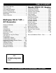
TABLE OF CONTENTS Here's How To Get Help ............................................ 3 Table Of Contents ..................................................... 4 Parts Ordering Procedures ....................................... 5 Rules For Safe Operation ......................................... 6 Operation and Safety Decals .................................... 7 Specifications ............................................................ 8 General Information ................................................
PARTS ORDERING PROCEDURES n n n n n n n Dealer account number Dealer name and address Shipping address (if different than billing address) Return fax number Applicable model number Quantity, part number and description of each part Specify preferred method of shipment: • • • • UPS Ground UPS Second Day or Third Day* UPS Next Day* Federal Express Priority One (please provide us with your Federal Express account number)* • • Airborne Express* Truck or parcel post *Normally shipped the same day the order
RULES FOR SAFE OPERATION CAUTION: Failure to follow instructions in this manual may lead to serious injury or even death! This equipment is to be operated by trained and qualified personnel only! This equipment is for industrial use only. The following safety guidelines should always be used when operating the GA-9.7 HZ Generator: GENERAL SAFETY ■ DO NOT operate or service this equipment before reading this entire manual. ■ This equipment should not be operated by persons under 18 years of age.
OPERATION AND SAFETY DECALS Machine Safety Decals The GA-9.7 HZ portable generator is equipped with a number of safety decals. These decals are provided for operator safety and maintenance information. The illustration below shows these decals as they appear on the machine. Should any of these decals become unreadable, replacements can be obtained from your dealer. GA-9.7 HZ A.C. GENERATOR — PARTS & OPERATION MANUAL — REV.
GA-9.7 HZ — SPECIFICATIONS Table 1. Specifications MODEL Type GA-9.7 HZ 2-pole, Brushless Type Revolving Field Max. Output 9700 Watts Rated Output (continuous) 8400 Watts Rated Voltage 120/240 V Rated Current 20.0/30.0 A 60 Cycle Generator Phase Frequency 3600 RPM Power Factor 100% Honda GX610K1VD Type Air-cooled 4 stroke OVH 90 V- Twin horizontal shaft gasoline engine Bore X Stroke 3.03 in X 2.60 in Displacement 18.8 cc Rated Output 18.0 H.P./3600 R.P.M.
GA-9.7 HZ — GENERAL INFORMATION WARNING: Before connecting this generator to any building’s electrical system, a licensed electrician must install an isolation (transfer) switch. Serious injury or death may result without this transfer switch. GA-9.7 HZ FAMILIARIZATION Generator The Multiquip Model GA-9.7 HZ generator has been designed as a portable lightweight power source for 60 Hz (singlephase) vibrators, lighting facilities, power tools, submersible pumps and other industrial and construction machinery.
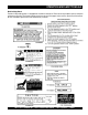
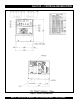
GA-9.7 HZ — CONTROLS AND INDICATORS Figure 1. Controls and Indicators PAGE 10 — GA-9.7 HZ A.C. GENERATOR— PARTS & OPERATION MANUAL — REV.
GA-9.7 HZ — INSTALLATION Outdoor Installation Indoor Installation Install the generator in a location where it will not be exposed to rain or sunshine. Make sure that the generator is on secure level ground so that it cannot slide or shift around. Also install the generator in a manner so that the exhaust will not be discharged in the direction of nearby homes. Exhaust gases from gasoline engines are extremely poisonous.
GA-9.7 HZ — PRE-SETUP General Inspection Prior to Operation Circuit Breaker This generator has been thoroughly inspected prior to shipment from the factory. However, be sure to check for damaged parts or components, or loose nuts and bolts, which could have occurred in transit. To protect the generator from an overload, circuit breakers are provided for single (60 Hz) phase on the control box. Make sure to switch the circuit breakers to the "OFF" position prior to starting the engine.
GA-9.7 HZ — PRE-SETUP Lubrication Oil Fuel Fill the engine crankcase with lubricating oil through the filler hole, but do not overfill. Make sure the generator is level. With the dipstick inserted all the way, but without being screwed into the filler hole, verify that the oil level is maintained between the two notches on the dipstick. Fill the fuel tank with clean and fresh unleaded gasoline. Do not fill the tank beyond capacity.
GA-9.7 HZ — INSTRUMENTATION CAUTION : Idle Control Switch When using a combination of dual receptacles, total load should not exceed the rated capacity of the generating. Power Outlets The generator has the following 60 Hz 120/240 volt singlephase receptacles. l Single Phase Two Duplex NEMA (GFCI) 5-20R (120V, 20 Amp) This unit is provided with an automatic idle control for noise suppression and reduced fuel consumption. The automatic idle control automatically engages under a no-load condition.
GA-9.7 HZ — LOAD APPLICATION Single Phase Load Always be sure to check the nameplate on the generator and equipment to insure the wattage, amperage and frequency requirements are satisfactorily supplied by the generator for operating the equipment. Generally, the wattage listed on the nameplate of the equipment is its rated output. Equipment may require 130— 150% more wattage than the rating on the nameplate, as the wattage is influenced by the efficiency, power factor and starting system of the equipment.
GA-9.7 HZ — OPERATING INSTRUCTIONS Before Starting Warm up 1. Be sure to disconnect the electrical load and switch the main circuit breaker to the “OFF” position prior to starting the engine. 1. When the engine starts, open the choke slowly. 2. Run the engine at low speed for 3 minutes without load until the engine warms up. 2. Never start the engine with the main circuit breaker “ON”. 3.
GA-9.7 HZ — MAINTENANCE General Inspection At least daily or prior to each use, the generating set should be cleaned and inspected for deficiencies. Check for loose, missing or damaged nuts, bolts or other fasteners. Also check for fuel or oil leaks. Service Daily Engine Side (Refer to the Engine Instruction Manual) Cleaning the Fuel Strainer Check Oil Level Clean the fuel strainer if it contains dust or water. Remove dust or water in the strainer cap and wash it in gasoline.
GA-9.7 HZ — PREPARATION FOR LONG -TERM STORAGE Generator Storage For storage of the generating set for over 30 days, the following is required: l Drain the fuel tank completely. l Run the engine until the gasoline in the carburetor is completely consumed. l Completely drain the oil from the crankcase and refill with fresh oil. l Remove the spark plug, pour 2 or 3 cc of SAE 30 oil into the cylinder and crank slowly to distribute the oil.
GA-9.7 HZ — WIRING DIAGRAM GA-9.7 HZ A.C. GENERATOR — PARTS & OPERATION MANUAL — REV.
GA-9.7 HZ — TROUBLESHOOTING (ENGINE) Practically all breakdowns can be prevented by proper handling and maintenance inspections, but in the event of a breakdown, please take a remedial action following the diagnosis based on the Engine Troubleshooting (Table 4) information shown below and on the proceeding page. If the problem cannot be remedied, please leave the unit just as it is and consult our company's business office or service plant. TABLE 4.
GA-9.7 HZ — TROUBLESHOOTING (ENGINE) TABLE 4. ENGINE TROUBLESHOOTING (CONTINUED) SYMPTOM Insufficient power output "compression" and overheats Burns to much fuel Exhaust color is continiously "WHITE" Exhaust color is continiously "BLACK" POSSIBLE PROBLEM SOLUTION Malfunction in cooling fan? Check or replace cooling fan. Air in-take filter clogged? Clean or replace air in-take filter. Over accumulation of exhaust products? Clean and check valves. Check muffler, replace if necessary.
GA-9.7 HZ — TROUBLESHOOTING (GENERATOR) Practically all generator breakdowns can be prevented by proper handling and maintenance inspections, but in the event of a breakdown, please take a remedial action following the diagnosis based on the Generator Troubleshooting (Table 5) information shown below and on the preceding page. If the problem cannot be remedied, please leave the unit just as it is and consult our company's business office or service plant. TABLE 5.
GA-9.7 HZ — TROUBLESHOOTING (GENERATOR) TABLE 5. GENERATOR TROUBLESHOOTING (CONTINUED) SYMPTOM Does not decelerate no "VOLTAGE OUTPUT". Does not decelerate but has "VOLTAGE OUTPUT". POSSIBLE PROBLEM SOLUTION Defective rotor windings? Check or replace rotor. Defective solenoid? Check or replace solenoid. Defective idle control device? Check or replace idle control device. Defective solenoid? Check or replace idle control device.
GA-9.7 HZ — EXPLANATION OF CODE IN REMARKS COLUMN How to read the marks and remarks used in this parts book. Items Found In the “Remarks” Column Serial Numbers-Where indicated, this indicates a serial number range (inclusive) where a particular part is used. Model Number-Where indicated, this shows that the corresponding part is utilized only with this specific model number or model number variant.
GA-9.7 HZ — SUGGESTED SPARE PARTS GA-9.7 1 TO 3 UNITS WITH HONDA GX610K1VD ENGINE 1 to 3 Units Qty. P/N Description 4 ............ 0601823204 .......... RECTIFIER 4 ............ 0601823754 .......... RELAY 1 ............ 0601807459 .......... CIRCUIT BREAKER 2 ............ 0601812529 .......... RECEPTABLE 1 ............ 0601811032 .......... RECEPTACLE, 250V, 20A 2 ............ 0601811031 .......... RECEPTACLE 1 ............ 0601812597 .......... RECEPTACLE 1 ............ 0601806425 ..........
GA-9.7 HZ — GENERATOR ASSY. GENERATOR ASSY. PAGE 26 — GA-9.7 HZ A.C. GENERATOR— PARTS & OPERATION MANUAL — REV.
GA-9.7 HZ — GENERATOR ASSY. GENERATOR ASSY. NO PART NO PART NAME 1 1-1 1-2 1-3 2 3 4 5 6 7 8 9 10 11 12 13 14 15 16 A6110200103 ROTOR ASSY. 1 INCLUDES ITEMS W/ FIELD ASSY. 1 RECTIFIER 2 BEARING .................................... 1 .....................REPLACES 0071206304 FAN 1 SET BOLT, ROTOR 1 SET WASHER BEARING 1 SPRING WASHER 1 ARMATURE ASSY. 1 END BRACKET 1 END BRACKET 1 COVER, STATOR 1 SET BOLT, STATOR 4 SPRING WASHER 4 PLAIN WASHER .......................... 4 .....................
GA-9.7 HZ — CONTROL BOX ASSY. CONTROL BOX ASSY. PAGE 28 — GA-9.7 HZ A.C. GENERATOR— PARTS & OPERATION MANUAL — REV.
GA-9.7 HZ — CONTROL BOX ASSY. CONTROL BOX ASSY.
GA-9.7 HZ — PIPE FRAME ASSY. PIPE FRAME ASSY. PAGE 30 — GA-9.7 HZ A.C. GENERATOR— PARTS & OPERATION MANUAL — REV.
GA-9.7 HZ — PIPE FRAME ASSY. PIPE FRAME ASSY. NO PART NO PART NAME 1 2 3 3-1 3-2 4 5 6 7 8 9 10 11 12 13 14 A6418000402 A6415100003 A6365000402 0810105900 PIPE FRAME 1 FLOOR PANEL 1 FUEL TANK 1 CAP, FUEL TANK ....................... 1 FUEL FILTER 1 DRAIN PLUG 1 O RING 1 FUEL GAUGE 1 HEX. HEAD BOLT ..................... 4 HEX. HEAD BOLT ...................11 BASE 1 RUBBER SUSPENSION 2 HEX. NUT 2 RUBBER SUSPENSION ........... 2 HEX. NUT 2 HEX. HEAD BOLT 2 HEX. NUT 2 HEX.
GA-9.7 HZ — NAMEPLATE ASSY. NAMEPLATE ASSY. PAGE 32 — GA-9.7 HZ A.C. GENERATOR— PARTS & OPERATION MANUAL — REV.
GA-9.7 HZ — NAMEPLATE ASSY. NAMEPLATE ASSY. NO PART NO PART NAME NAME PLATE QTY. 1 2 3 4 5 6 7 8 9 10 11 12 13 0800628504 0800696604 1630645004 7810680104 8700611804 8700611904 B9504000304 D2552000404 0820610804 0820610404 7900636004 8700611524 A6562100003 DECAL; GROUND 1 DECAL; BATTERY 1 DECAL; OIL DRAIN 1 DECAL; FUEL DRAIN 1 DECAL; WARNING DANGEROUS 1 DECAL; DANGER ELECTRICAL 1 DECAL; CAUTION HOT PARTS 1 DECAL; OPERATING INSTRUCTIONS 1 DECAL; CAUTION! ................................. 1 ..........
HONDA GX610K1 ENGINE — CYLINDER HEAD ASSY. CYLINDER HEAD ASSY. HONDA GX610K1 ENGINE — CYLINDER HEAD PAGE 34 — GA-9.7 HZ A.C. GENERATOR— PARTS & OPERATION MANUAL — REV.
HONDA GX610K1 ENGINE — CYLINDER HEAD ASSY. CYLINDER HEAD ASSY. NO PART NO 1 2 3 4 5 6 7 8 9 10 11 12 13 14 15 16 17 18 19 12210ZJ1000 12220ZJ1U80 12205ZE2305 12216ZE2300 12251ZJ1003 12311ZJ1000 12314ZJ1000 12391ZJ1000 15611921000 17101ZJ1000 17151ZJ1003 90121ZJ1000 91301805000 92900080250B 9430112200 957010603200 957011007500 957011013000 9807956846 * * PART NAME QTY. REMARKS CYLINDER HEAD COMP., R. ........... 1 ..... INCLUDES ITEMS W/ CYLINDER HEAD COMP., L. ............ 1 .....
HONDA GX610K1 ENGINE — CYLINDER BARREL ASSY. CYLINDER BARREL ASSY. PAGE 36 — GA-9.7 HZ A.C. GENERATOR— PARTS & OPERATION MANUAL — REV.
HONDA GX610K1 ENGINE — CYLINDER BARREL ASSY. CYLINDER BARREL ASSY. NO PART NO PART NAME 1 2 3 4 5 12000ZJ1810 12356ZJ1000 12358ZJ1000 12372ZE2300 13321ZJ1000 13322ZJ1000 13323ZJ1000 15400PR3004 25523VD6010 31511ZJ1000 35480ZJ1812 90014ZE6000 90018PN3000 90029888000 90031ZE1000 91201ZJ1003 91353671004 9280014000 9405010000 9410914000 957010607509 961406003010 CYLINDER BARREL ASSY. ....................................... 1 ...........
HONDA GX610K1 ENGINE — CRANKCASE COVER ASSY. CRANKCASE COVER ASSY. PAGE 38 — GA-9.7 HZ A.C. GENERATOR— PARTS & OPERATION MANUAL — REV.
HONDA GX610K1 ENGINE — CRANKCASE COVER ASSY. CRANKCASE COVER ASSY. NO PART NO PART NAME 1 2 3 4 11300ZJ1000 11381ZJ1000 12105ZAO701 13321ZJ1000 13322ZJ1000 13323ZJ1000 15120ZJ1000 15124ZJ1003 15232ZJ1000 15348ZJ1000 15427ZJ1000 15655ZJ1000 16541ZJ1000 16542ZJ1000 91201ZJ1003 91259NM0000 91302MB6830 93500050100A 9430108140 957010602000 957010805000 9621112000 966000601600 COVER ASSY.
HONDA GX610K1 ENGINE — CRANKSHAFT ASSY. CRANKSHAFT ASSY. PAGE 40 — GA-9.7 HZ A.C. GENERATOR— PARTS & OPERATION MANUAL — REV.
HONDA GX610K1 ENGINE — CRANKSHAFT ASSY. CRANKSHAFT ASSY. NO PART NO PART NAME 3 5 13310ZJ0880 90401ZJ1000 CRANKSHAFT COMP. WASHER, CRANKSHAFT THRUST QTY. REMARKS 1 1 GA-9.7 HZ A.C. GENERATOR — PARTS & OPERATION MANUAL — REV.
HONDA GX610K1 ENGINE — PISTON ASSY. PISTON ASSY. PAGE 42 — GA-9.7 HZ A.C. GENERATOR— PARTS & OPERATION MANUAL — REV.
HONDA GX610K1 ENGINE — PISTON ASSY. PISTON ASSY. NO PART NO PART NAME 1 13010ZE8601 13011ZE8601 13012ZE8601 13013ZE8601 13101ZJ1000 13102ZJ1000 13103ZJ1000 13104ZJ1000 13111ZJ1000 13210ZJ1000 13211ZJ1003 13212ZJ1003 13213ZJ1003 13214ZJ1003 13215ZJ1003 13216ZJ1003 13217ZJ1003 13213ML0000 13215KM3000 9460118000 RING SET, PISTON (STD) 2 RING SET, PISTON (0.25) 2 RING SET, PISTON (0.50) 2 RING SET, PISTON (0.75) 2 PISTON 2 PISTON (0.25) 2 PISTON (0.50) 2 PISTON (0.75) 2 PIN, PISTON 2 ROD SET, CONNECTING ..
HONDA GX610K1 ENGINE — CAMSHAFT ASSY. CAMSHAFT ASSY. PAGE 44 — GA-9.7 HZ A.C. GENERATOR— PARTS & OPERATION MANUAL — REV.
HONDA GX610K1 ENGINE — CAMSHAFT ASSY. CAMSHAFT ASSY.
HONDA GX610K1 ENGINE — RECOIL STARTER ASSY. RECOIL STARTER ASSY. PAGE 46 — GA-9.7 HZ A.C. GENERATOR— PARTS & OPERATION MANUAL — REV.
HONDA GX610K1 ENGINE — RECOIL STARTER ASSY. RECOIL STARTER ASSY. NO PART NO PART NAME 1 2 * 3 * 4 * 5 * 6 * 7 * 8 * 9 * 10 * 11 * 12 * 13 * 14 28400ZE3W01ZA 28410ZE3W01ZA 28421ZE3W01 28422ZE2W01 28441ZE2W01 28442ZE2W01 28443ZE2W01 28444ZE2W01 28445ZE2W01 28461ZE2W01 28462ZH8003 28469ZE2W01 90004ZE2W01 957010600800 STARTER ASSY., RECOIL R8 (BRT. RED) 1 INCLUDES ITEMS W/ * CASE COMP.
HONDA GX610K1 ENGINE — FAN COVER ASSY. FAN COVER ASSY. PAGE 48 — GA-9.7 HZ A.C. GENERATOR— PARTS & OPERATION MANUAL — REV.
HONDA GX610K1 ENGINE — FAN COVER ASSY. FAN COVER ASSY. NO PART NO PART NAME 2 4 5 6 7 10 11 12 13 16 17 18 19 20 21 24 25 26 19611ZJ1800ZB 19612ZJ1000 19614ZJ1000 19615ZJ1000 19617ZJ4000 19631ZJ1000 19632ZJ1000 28405ZJ1801ZB 33713GC2000 90013883000 90018ZE1000 90042ZJ1000 90055ZE1000 90104GF6000 90113GE4000 90683SD9781 9405006000 957010600800 COVER, FAN R8 (RECOIL STARTER)(BRT.RED) PLATE, R. SIDE PLATE, L SIDE HOOD FAN COVER COVER, R. SIDE PLATE SHROUD, R. SHROUD, L.
HONDA GX610K1 ENGINE — CARBURETOR ASSY. CARBURETOR ASSY. PAGE 50 — GA-9.7 HZ A.C. GENERATOR— PARTS & OPERATION MANUAL — REV.
HONDA GX610K1 ENGINE — CARBURETOR ASSY. CARBURETOR ASSY. NO PART NO PART NAME 1 2 3 # 4 5 6 7 8 # 9 10 11 12 13 14 15 16 17 18 19 20 21++ 22 23 12357ZJ1000 15772551000 16010ZG8000 16011382004 16013ZV4005 16015ZJ1000 16016ZJ1010 16024124760 16028ZG8000 16081ZV4650 16100ZJ0892 16148141881 16151ZJ0020 16166ZJ1010 16178548004 16200ZJ1003 16211ZJ1000 16221ZG8000 17228ZG8003 17410ZJ1000 19024ZA0000 90682959661 938920501218 TUBE, BREATHER 1 CLIP, BREATHER TUBE 1 GASKET SET 1 VALVE SET, FLOAT .................
HONDA GX610K1 ENGINE — AIR CLEANER ASSY. AIR CLEANER ASSY. PAGE 52 — GA-9.7 HZ A.C. GENERATOR— PARTS & OPERATION MANUAL — REV.
HONDA GX610K1 ENGINE — AIR CLEANER ASSY. AIR CLEANER ASSY. NO PART NO PART NAME 1 2 3 4 5 6 7 8 9 10 11 13 14 15 16 17 18 19 17010ZJ1000 17216ZJ1000 17217ZJ1000 17218ZJ1000 17220ZJ1000 17231ZJ1000 17232ZJ1000 17237ZJ1000 17251ZJ1000 17255758000 17257HB3000 90017ZJ1000 90018ZE1000 90120102000 93500040200A 93500040250G 938910501608 957000601800 ELEMENT SET, AIR CLEANER ................... 1 .......... INCLUDES ITEMS W/ GASKET A, ELEMENT 1 GASKET B, ELEMENT 1 FILTER (OUTER) 1 HOUSING COMP.
HONDA GX610K1 ENGINE — MUFFLER ASSY. MUFFLER ASSY. PAGE 54 — GA-9.7 HZ A.C. GENERATOR— PARTS & OPERATION MANUAL — REV.
HONDA GX610K1 ENGINE — MUFFLER ASSY. MUFFLER ASSY. NO 1 2 3 4 5 6 7 8 9 10 11 PART NO PART NAME 18310ZJ1000 18321ZJ1000 18330ZJ1601 18333ZJ1000 18396ZJ1003 957010600800 957010801400 957010802000 18333ZJ1000 99405008000 MUFFLER KIT 1 NOT AVAILABLE, SEE COMPONENTS MUFFLER COMP. ............................. 1 ..... 18310ZJ1003 PROTECTOR,MUFFLER ................ 1 ..... 18321ZJ1003 PIPE COMP., EX. 1 STAY, MUFFLER .............................. 1 ..... 18338ZJ1003 BAND ASSY.
HONDA GX610K1 ENGINE — FUEL PUMP ASSY. FUEL PUMP ASSY. PAGE 56 — GA-9.7 HZ A.C. GENERATOR— PARTS & OPERATION MANUAL — REV.
HONDA GX610K1 ENGINE — FUEL PUMP ASSY. FUEL PUMP ASSY. NO PART NO PART NAME 1 2 4 5 6 7 8 9 10 11 12 13 14 15 16700ZJ1003 16711ZJ1800 16910ZE8015 19905ZA8701 35806752630 90617SA0003 950014511040 950015519540 950015521540 9500202080 950024105008 950033601620 957010600800 957010601400 PUMP ASSY., FUEL STAY, FUEL PUMP STRAINER COMP., FUEL GROMMET, WIRE BASE, CLIP CLIP, WIRE HARNESS BULK HOSE, FUEL (4.5X110) BULK HOSE, FUEL (5.5X195) BULK HOSE, FUEL (5.5X215) CLIP, TUBE (B8) CLIP, TUBE (10.
HONDA GX610K1 ENGINE — FLYWHEEL ASSY. FLYWHEEL ASSY. PAGE 58 — GA-9.7 HZ A.C. GENERATOR— PARTS & OPERATION MANUAL — REV.
HONDA GX610K1 ENGINE — FLYWHEEL ASSY. FLYWHEEL ASSY. NO PART NO PART NAME 1 3 6 8 10 11 12 13 15 19511ZJ1000 28451ZJ1801 28453ZJ1801 31110ZJ1811 90013ZJ1800 90201ZG3000 90401ZG3000 90741ZE2000 957010801600 FAN, COOLING PULLEY, STARTER SPACER, STARTER PULLEY MT. FLYWHEEL COMP. BOLT, UBS (12X28) NUT, FLANGE (20MM) WASHER (20MM) KEY, SPECIAL WOODRUFF (25X18) BOLT, FLANGE (8X16) QTY. REMARKS 1 1 1 1 1 1 1 1 3 GA-9.7 HZ A.C. GENERATOR — PARTS & OPERATION MANUAL — REV.
HONDA GX610K1 ENGINE — IGNITION COIL ASSY. IGNITION COIL ASSY. PAGE 60 — GA-9.7 HZ A.C. GENERATOR— PARTS & OPERATION MANUAL — REV.
HONDA GX610K1 ENGINE — IGNITION COIL ASSY. IGNITION COIL ASSY. NO PART NO PART NAME 1 2 3 4 5 7 8 9 11 12 13 14 15 30500ZJ1013 30518ZJ1000 30550ZJ1013 30700ZJ1003 31630ZJ1003 31740ZJ1003 63312ZA7000 90014ZE6000 901219052000 90658SA0003 90673GJ5003 901504750003 957010600800 COIL ASSY., R. IGNITION GROMMET, IGNITION WIRE COIL ASSY., L. IGNITION CAP ASSY., NOISE SUPPRESSER COIL ASSY., CHARGE (12V/3A) DIODE ASSY.
HONDA GX610K1 ENGINE — STARTER MOTOR ASSY. STARTER MOTOR ASSY. PAGE 62 — GA-9.7 HZ A.C. GENERATOR— PARTS & OPERATION MANUAL — REV.
HONDA GX610K1 ENGINE — STARTER MOTOR ASSY. STARTER MOTOR ASSY. NO PART NO PART NAME 1 2 3 4 5 6 7 8 9 10 31200ZJ1004 31243ZJ1800 32402ZJ1810 32411KB9930 32411402000 35850ZJ1811 9405006000 9407006080 9430110120 957010811000 MOTOR ASSY., STARTER 1 BRACKET, STARTER MAGNETIC SET. 1 CABLE, MAGNET SWITCH ............................. 1 ......... INCLUDES ITEMS W/ COVER A, MAGNETIC SWITCH 1 COVER, STARTER. MOTOR TERMINAL 1 SWITCH ASSY.
HONDA GX610K1 ENGINE — GOVERNOR/CONTROL ASSY. GOVERNOR/CONTROL ASSY. PAGE 64 — GA-9.7 HZ A.C. GENERATOR— PARTS & OPERATION MANUAL — REV.
HONDA GX610K1 ENGINE — GOVERNOR/CONTROL ASSY. GOVERNOR/CONTROL ASSY.
HONDA GX610K1 ENGINE — LABELS LABELS PAGE 66 — GA-9.7 HZ A.C. GENERATOR— PARTS & OPERATION MANUAL — REV.
HONDA GX610K1 ENGINE — LABELS LABELS NO PART NO PART NAME 1 2 3 5 87101ZJ0000 87152ZJ0000 87522ZJ1000 87532ZH8810 MARK, EMBLEM (GX610) LABEL, SPECIFICATION (GX610) LABEL, CAUTION MARK, OIL ALERT (E) QTY. REMARKS 1 1 1 1 GA-9.7 HZ A.C. GENERATOR — PARTS & OPERATION MANUAL — REV.
HONDA GX610K1 ENGINE —GASKET KIT GASKET KIT NO PART NO PART NAME 1 2 3 4 5 6 7 8 9 061A1ZJ1000 11381ZJ1000 12251ZJ1003 12358ZJ1000 12391ZJ1000 16221ZG8000 17151ZJ1003 17228ZG8003 18333ZJ1000 91301805000 GASKET KIT ..................................... 1 ........... INCLUDES ITEMS W/ GASKET, CASE COVER 1 GASKET, CYLINDER HEAD 2 GASKET, BREATHER COVER 1 GASKET, HEAD COVER 2 GASKET, CARBURETOR 2 GASKET, IN. MANIFOLD 2 GASKET, AIR CLEANER 1 GASKET, EX. PIPE 2 ORING (26X2.7) 1 * * * * * * * * QTY.
TERMS AND CONDITIONS OF SALE — PARTS Effective: July 1, 2000 PAYMENT TERMS 4. Terms of payment for parts are net 10 days. FREIGHT POLICY All parts orders will be shipped collect or prepaid with the charges added to the invoice. All shipments are F.O.B. point of origin. Multiquip’s responsibility ceases when a signed manifest has been obtained from the carrier, and any claim for shortage or damage must be settled between the consignee and the carrier. Freight is at the sender’s expense.
PARTS AND OPERATION MANUAL HERE'S HOW TO GET HELP PLEASE HAVE THE MODEL AND SERIAL NUMBER ON-HAND WHEN CALLING PARTS DEPARTMENT 800/427-1244 or 310/537-3700 FAX: 800/672-7877 or 310/637-3284 SERVICE DEPARTMENT 800/478-1244 or 310/537-3700 FAX: 310 - 537-4259 WARRANTY DEPARTMENT 800/421-1244, EXT. 279 or 310/537-3700 FAX: 310 - 537-1173 MAIN 800/421-1244 or 310/537-3700 FAX: 310 - 537-3927 Manufactured for MULTIQUIP INC. by DENYO MANUFACTURING CO., USA MULTIQUIP INC.