© COPYRIGHT 2002, MULTIQUIP INC. PARTS AND OPERATION MANUAL Model KD1800/KD6 A.C. GENERATOR USED WITH MLT SERIES MODULAR LIGHT TOWERS Revision #1 (06/16/05) MULTIQUIP INC.. PARTS DEPARTMENT: 18910 WILMINGTON AVE. 800-427-1244 CARSON, CALIFORNIA 90746 FAX: 800-672-7877 SERVICE DEPARTMENT/TECHNICAL ASSISTANCE: 310-537-3700 800-421-1244 800-478-1244 FAX: 310-537-3927 FAX: 310-631-5032 E-mail:mq@multiquip.com • www:multiquip.
PAGE 2 —KD1800/KD6 A.C. GENERATOR— PARTS & OPERATION MANUAL — REV.
HERE'S HOW TO GET HELP PLEASE HAVE THE MODEL AND SERIAL NUMBER ON-HAND WHEN CALLING PARTS DEPARTMENT 800-427-1244 or 310-537-3700 FAX: 800-672-7877 or 310-637-3284 SERVICE DEPARTMENT/TECHNICAL ASSISTANCE 800-478-1244 or 310-537-3700 FAX: 310- 537-4259 WARRANTY DEPARTMENT 888-661-4279, or 310-661-4279 FAX: 310- 537-1173 MAIN 800-421-1244 or 310-537-3700 FAX: 310-537-3927 KD1800/KD6 A.C. GENERATOR — PARTS & OPERATION MANUAL — REV.
TABLE OF CONTENTS Here's How To Get Help ............................................ 3 Table Of Contents ..................................................... 4 Parts Ordering Procedures ....................................... 5 Safety Alert Message Symbols .............................. 6-7 Rules For Safe Operation ...................................... 8-9 Operation and Safety Decals ............................. 10-11 Generator Specifications ........................................
PARTS ORDERING PROCEDURES ■ ■ ■ ■ ■ ■ ■ Dealer account number Dealer name and address Shipping address (if different than billing address) Return fax number Applicable model number Quantity, part number and description of each part Specify preferred method of shipment: • • • • UPS Ground UPS Second Day or Third Day* UPS Next Day* Federal Express Priority One (please provide us with your Federal Express account number)* • • Airborne Express* Truck or parcel post *Normally shipped the same day the order
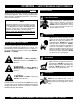
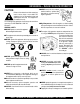
KD1800/KD6 — SAFETY MESSAGE ALERT SYMBOLS FOR YOUR SAFETY AND THE SAFETY OF OTHERS! Safety precautions should be followed at all times when operating this equipment. Failure to read and understand the Safety Messages and Operating Instructions could result in injury to yourself and others. NOTE This Owner's Manual has been developed to provide complete instructions for the safe and efficient operation of the MQ Whiteman Model KD1800/KD6 6KW Generator.
KD1800/KD6 — SAFETY MESSAGE ALERT SYMBOLS Accidental Starting ALWAYS place the ignition switch in the OFF position, remove key when the equipment is not in use. Store key in a safe place. Over Speed Conditions NEVER tamper with the factory settings of the engine governor or settings. Personal injury and damage to the engine or equipment can result if operating in speed ranges above maximum allowable. Sight and Hearing hazard ALWAYS wear approved eye and hearing protection.
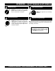
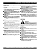
KD1800/KD6 — RULES FOR SAFE OPERATION CAUTION: Failure to follow instructions in this manual may lead to serious injury or even death! This equipment is to be operated by trained and qualified personnel only! This equipment is for industrial use only. The following safety guidelines should always be used when operating the KD1800/KD6 6 KW AC Generator: GENERAL SAFETY ■ DO NOT operate or service this equipment before reading this entire manual.
KD1800/KD6 — RULES FOR SAFE OPERATION ■ DO NOT operate or service this equipment before reading this entire manual. ■ This equipment should not be operated by persons under 18 years of age. ■ Provide adequate ventilation when operating the generator. DO NOT operate the generator in any enclosed or narrow space. The gasoline engine that provides power to the generator gives off DEADLY monoxide gas.
KD1800/KD6 — OPERATION AND SAFETY DECALS Machine Safety Decals The KD1800/KD6 generator is equipped with a number of safety decals. These decals are provided for operator safety and maintenance information. The illustration below shows these decals as they appear on the machine. Should any of these decals become unreadable, replacements can be obtained from your dealer. For a complete decal sheet order P/N 29345. PAGE 10 —KD1800/KD6 A.C. GENERATOR— PARTS & OPERATION MANUAL — REV.
KD1800/KD6 — OPERATION AND SAFETY DECALS KD1800/KD6 A.C. GENERATOR — PARTS & OPERATION MANUAL — REV.
KD1800/KD6 — GENERATOR SPECIFICATIONS TABLE 1. GENERATOR SPECIFICATIONS Model Marathon 332CSA5203 Phase Single Phase Maximum Output 6,000 Watts Continious Output 6,000 Watts Rated Voltage 120/240 Volts Amps at 120/240 50/25 Amps Frequency 60 Hz. Speed 1,800 rpm Dry Weight1 110 lbs. (50 Kg.) Generator Only Dry Weight2 702 lbs (305 Kg.) Complete 1. This weight is for the generator only. It DOES NOT include the cabinet. 2.
KD1800/KD6 — GENERATOR SPECIFICATIONS TABLE 2. ENGINE SPECIFICATIONS Model KUBOTA D905-EBG-2E Rated Output (Gross Intermittent) Power 13.7 HP @1,800 rpm's 23.0 HP @3,000 rpm's Net Continous Power 10.2 HP @1,800 rpm's 17.0 HP @3,000 rpm's Displacement 54.80 cu. in (898 cm2) Combustion Chamber Spherical Type (9E-TVCS) Maximum Bare Idle Speed 3,800 rpm's Number of Cylinders 3 Cooling System Water-Cooled Fuel Tank Capacity* 30 gal.
KD1800/KD6 — GENERAL INFORMATION KD1800/KD6 FAMILIARIZATION Generator Housed within the KD1800/KD6 generator package is a Marathon Model 332, 6,000 watt (6-KW) generator. This generator can provide up to 50 amps of current. In addition two voltage output receptacles have been provided on the generator's control box. One receptacle has an output of 120/250 VAC and the other is a 120 VAC, GFCI protected receptacle. The Marathon Model 332 generator should only be operated at a frequency of 60 hertz.
KD1800/KD6 — DIMENSIONS Figure 1. KD1800/KD6 Dimensions KD1800/KD6 A.C. GENERATOR — PARTS & OPERATION MANUAL — REV.
KD1800/KD6 — CONTROLS AND INDICATORS Figure 2. KD1800/KD6 Components PAGE 16 —KD1800/KD6 A.C. GENERATOR— PARTS & OPERATION MANUAL — REV.
KD1800/KD6 — CONTROLS AND INDICATORS Figure 2 shows the location of the controls and indicators of the KD1800/KD6 generator. The functions of each control or indicator is described below: 1. Radiator Filler Port – Remove this plate to add coolant (anti-freeze) to the radiator. NEVER add coolant to the radiator when the radiator is HOT!. Allow the radiator to cool before adding coolant. Use a water coolant mixture as recommended in the maintenance section of this manual. 2.
KD1800/KD6 — INSTALLATION Outdoor Installation Install the generator in a location where it will not be exposed to rain or sunshine. Make sure that the welder/generator is on secure level ground so that it cannot slide or shift around. Also install the generator in a manner so that the exhaust will not be discharged in the direction of nearby homes. The installation site must be relatively free from moisture and dust. All electrical equipment should be protected from excessive moisture.
KD1800/KD6 — PRE-SETUP (GENERATOR) General Inspection Prior to Operation The KD1800/KD6 utilizes a generator that has been thoroughly inspected and accepted prior to shipment from the factory. However, be sure to check for damaged parts or components, or loose nuts and bolts, which could have occurred in transit. Generator Grounding To guard against electrical shock and possible damage to the equipment, it is important to provide a good EARTH ground.
KD1800/KD6 — PRE-SETUP (GENERATOR) Circuit Breakers To protect the generator from an overload, a 2-pole, 30 amp, main circuit breaker is provided. In addition a single pole, 15 amp breaker is provided for the G.F.C.I. receptacle. Make sure to switch both circuit breakers to the "OFF" position prior to starting the engine. Extension Cable When electric power is to be provided to various tools or loads at some distance from the generator, extension cords are normally used.
KD1800/KD6 — PRE-SETUP (ENGINE) Lubrication Oil (Engine) Fuel Fill the engine crankcase with lubricating oil through the filler hole, but do not overfill. Make sure the generator is level. With the dipstick inserted all the way into its holder. Verify that the oil level is maintained between the two notches (Figure 4) on the dipstick. See Table 4 for proper selection of engine oil. Fill the fuel tank with No. 2 diesel fuel. DO NOT fill the tank beyond capacity.
KD1800/KD6 — PRE-SETUP (ENGINE) Fan Belt Tension CAUTION : When adding coolant or anti-freeze to the radiator, DO NOT remove the radiator cap until the unit has completely cooled. A slack fan belt may contribute to overheating, or to insufficient charging of the battery. Inspect and adjust it in accordance with the KUBOTA engine manual. The fan belt tension is proper if the fan belt (Figure 5) bends 7 to 9 mm (0.28- to 0.35) when depressed with the thumb as shown in Figure 8 below.
KD1800/KD6 — INSTRUMENTATION CAUTION : When using a combination of dual receptacles, total load should not exceed the rated capacity of the generator set. Power Outlets The generator has the following single-phase 60 Hz, 120/ 240 volt receptacles. z Single Phase One Duplex NEMA (GFCI) 5-15R (120V, 15 Amp) One Twist Lock NEMA L14-30R (120/240V, 30 Amp) Main Circuit Breaker (2-Pole) This 2-pole, 30 amp main breaker protects the 120/240 output receptacle from short circuiting or overloading.
KD1800/KD6 — LOAD APPLICATION Single Phase Load Always be sure to check the nameplate on the generator and equipment to insure the wattage, amperage and frequency requirements are satisfactorily supplied by the generator for operating the equipment. Generally, the wattage listed on the nameplate of the equipment is its rated output. Equipment may require 130— 150% more wattage than the rating on the nameplate, as the wattage is influenced by the efficiency, power factor and starting system of the equipment.
KD1800/KD6 — ENGINE OPERATING INSTRUCTIONS WARNING: z The engine's exhaust contains harmful emissions. ALWAYS ventilate the exhaust when operating inside tunnels, excavations or buildings. Direct exhaust away from nearby personnel. Before Starting 1. Be sure to disconnect the electrical load and switch the main circuit breaker to the "OFF" position prior to starting the engine. Also switch the GFCI circuit breaker to the "OFF" position. 2.
KD1800/KD6 — MAINTENANCE (ENGINE) General Inspection At least daily or prior to each use, the generator should be cleaned and inspected for deficiencies. Check for loose, missing or damaged nuts, bolts or other fasteners. Also check for fuel or oil leaks. Engine Side: For a more detail engine maintenance schedule refer to the KUBOTA Engine Shop and Operator's Manual. 6.
KD1800/KD6 — MAINTENANCE (ENGINE) 4. If the engine oil level is too low, remove the engine oil filler cap Figure 9, and fill to the correct operating level. Fuel Lines Every 50 hours: Check the fuel lines and associated clamp bands every 50 hours of operation. 1. If the rubber fuel lines and clamp bands become worn, replace them immediately. Replace all rubber fuel lines every two years. Replacing the Fuel Filter Every 400 hours: Replace the fuel filter (Figure 11) every 400 hours. Figure 9.
KD1800/KD6 — MAINTENANCE (ENGINE) Air Removal If air enters the fuel system of a diesel engine, starting becomes impossible. After running out of fuel, or after disassembling the fuel system, bleed the system according to the following procedure. To restart after running out of fuel, turn the key switch to the “START” position for 15-30 seconds. Try again, if needed. This unit is equipped with an automatic air bleeding system. 2.
KD1800/KD6 — MAINTENANCE (ENGINE) Anti-freeze Recommendations z Use rubber gloves when handling anti-freeze. z When anti-freeze comes in contact with the skin or clothing, wash it off immediately. z DO NOT mix different types of anti-freeze. z Keep fire, children and animals away from anti-freeze. z Check with local safety codes on the proper disposal techniques of anti-freeze. The battery is sufficiently charged if the specific gravity of the battery fluid is 1.28 (at 68° F).
KD1800/KD6 — MAINTENANCE (GENERATOR) Generator Capacitor Regulation A single capacitor is used to regulate the voltage to within 5% of the rated load. z ALWAYS USE EXTREME CAUTION when handling capacitors. The capacitor will still contain a high voltage even after the engine has been shut-down. z ALWAYS discharge the capacitor before handling. Use a conductor or a screwdriver (Figure 15) with an insulated handle. Place screwdriver across both capacitor terminals while holding onto the handle.
KD1800/KD6 — PREPARATION FOR LONG -TERM STORAGE Generator Storage For storage of the generator for over 30 days, the following is required: z Drain the fuel tank completely. z Completely drain the oil from the crankcase and refill with fresh oil. z Disconnect the negative battery cable from the battery. z Clean all external parts of the generator with a cloth. z Cover the generating set and store in a clean, dry place. KD1800/KD6 A.C. GENERATOR — PARTS & OPERATION MANUAL — REV.
KD1800/KD6 — TROUBLESHOOTING ( GENERATOR) Practically all breakdowns can be prevented by proper handling and maintenance inspections, but in the event of a breakdown, please take a remedial action following the diagnosis based on the Generator Troubleshooting (Table 8) information shown below . If the problem cannot be remedied, please leave the unit just as it is and consult our company's business office or service plant. TABLE 8.
KD1800/KD6 — TROUBLESHOOTING (ENGINE) Practically all breakdowns can be prevented by proper handling and maintenance inspections, but in the event of a breakdown, please take a remedial action following the diagnosis based on the Engine Troubleshooting (Table 9) information shown below and on the proceeding page . If the problem cannot be remedied, please leave the unit just as it is and consult our company's business office or service plant. TABLE 9.
KD1800/KD6 — TROUBLESHOOTING (ENGINE) TABLE 9. ENGINE TROUBLESHOOTING (C0NTINUED) SYMPTOM Engine revolution is not smooth. Either white or blue exhaust gas is observed. Either black or dark gray exhaust gas is observed. Deficient output. POSSIBLE PROBLEM SOLUTION Fuel filter clogged or dir ty? Clean or change. Air cleaner clogged? Clean or change. Fuel leak due to loose injection pipe retaining nut? Tighten nut. Injection pump malfunctioning? Repair or replace.
NOTE PAGE KD1800/KD6 A.C. GENERATOR — PARTS & OPERATION MANUAL — REV.
KD1800/KD6 — EXPLANATION OF CODES IN REMARKS COLUMN How to read the marks and remarks used in this parts book. Section 1: Items Found In the “Remarks” Column Serial Numbers-Where indicated, this indicates a serial number range (inclusive) where a particular part is used. Model Number-Where indicated, this shows that the corresponding part is utilized only with this specific model number or model number variant.
KD1800/KD6 — SUGGESTED SPARE PARTS KD1800/KD6 W/KUBOTA D905EBG-2 DIESEL ENGINE 1 TO 3 UNITS Qty. P/N Description 5 ............ 1627132092 .......... OIL FILTER 2 ............ 1491197010 .......... V-BELT 1 ............ 1522443013 .......... FUEL FILTER 5 ............ 29334 .................... OIL PRESSURE SENSOR 5 ............ 29333 .................... WATER TEMPERATURE SENSOR 1 ............ 20511 .................... IGNITION SWITCH 2 ............ 12940 .................... KEYS 1 ............ 29344 ...
KD1800/KD6 — NAMEPLATE AND DECALS PAGE 38 —KD1800/KD6 A.C. GENERATOR— PARTS & OPERATION MANUAL — REV.
KD1800/KD6 — NAMEPLATE AND DECALS ENCLOSURE ASSY. NO. 1 * 2 * 3 * 4 * 5 * 6 * 7 * 8 * 9 * 10 * 11 * 12 * 13 * 14 * 15 * 16 * 17 * 18 * 19 * 20 * 21 * 22 * 23 24 24 25 25 26 PART NO. DCL103 DCL117 DCL180 DCL181 DCL182 DCL183 DCL184 DCL185 DCL186 DCL187 DCL188 DCL189 DCL190 DCL191 DCL192 DCL193 DCL194 DCL195 DCL196 DCL197 DCL198 DCL199 29360 29358 29358 29359 29359 27 29345 PART NAME QTY.
KD1800/KD6 — ENCLOSURE ASSY. ENCLOSURE ASSY. PAGE 40 —KD1800/KD6 A.C. GENERATOR— PARTS & OPERATION MANUAL — REV.
KD-1800 /KD-6 — ENCLOSURE ASSY. ENCLOSURE ASSY. NO. 1 2 3 4 5 6 7 8 9 10 11 12 13 14 15 16 17 18 19 20 21 22 23 24 25 26 27 28 29 31 32 33 34 PART NO. 0131A 0447 0948 10024 10031 10176 10981 12287 19266 2691 29057 29258 29260 29262 29281 29282 29284 29285 29291 29297 29298 29299 29300 29316 29324 29340 29341 29342 29438 3214 4514 5054A 0181B PART NAME SCREW, HHC 1/4-20 WASHER, FLAT 1/2 SAE WASHER FLAT, 1/4 SAE NUT, NYLOC 1/4-20 WASHER, EXT SHKP 1/4 NUT, NYLOC 1/2-13 TERMINAL, RING 12 GA. X .
KD1800/KD6 — CONTROL BOX ASSY. CONTROL BOX ASSY. 8 CABINET TOP 13 8 12 21 20 2 22 FRONT VIEW 5 11 15 14 24 16 AC INPUT WIRING 10 20 3 2 25 1 ITCH E SW 27 STAR T DEMA RR 26 HA PRE H PRECEAT UF FA G E CT TA E S R AG T R N A T CO 8 9 2 6 7 17 13 3 BACK VIEW 19 24 18 28 23 NOTES: 1 INCLUDED WITH ITEM 25 23 24 4 1 13 3 2 INCLUDED WITH ITEM 7 3 INCLUDED WITH ITEM 14 PAGE 42 —KD1800/KD6 A.C. GENERATOR— PARTS & OPERATION MANUAL — REV.
KD1800/KD6 — CONTROL BOX ASSY. CONTROL BOX ASSY. NO. 1 2 3 4 5 6 7 8 9 10 11 12 13 14 15 16 17 18 19 20 21 22 23 24 25 26 27 28 PART NO. 0948 10019 10024 10031 26560 12307 29363 12287 1450 19212 19223 29376 19266 19695 6900446 6900447 19819 2673 29276 29277 29325 29343 4514 5065B 20511 12940 20486 29344 PART NAME WASHER, FLAT, 1/4 SAE NUT, NYLOC 10- 32 NUT, NYLOC 1/4- 20 WASHER, EXT. SHKP 1/4 NUT, LOCKING 3/4 NPT CONDUIT +12 DCV BULB ASSY. LIGHT, BLUE INDICATOR .75 DIA.
KD1800/KD6 — ENGINE MOUNTING HARDWARE ASSY. ENGINE MOUNTING HARDWARE ASSY. 19 20 2 19 14 1 6 12 14 5 12 6 5 4 CRADLE P/N 29263 3 15 6 10 12 9 2 1 17 11 6 7 8 6 18 15 16 3 1 BASE AND CRADLE SHOWN P/N 29297 CRADLE IS WELDED TO BASE 2 NOTES: ROUTE ENGINE CABLE HARNESS 1 THROUGH CLAMPS. USED WITH SERIAL NUMBERS 2 UP TO S/N FK30000051 ENGINE CRADLE CANNOT BE 3 PURCHASED SEPARATELY. ORDER P/N 29297 FOR ENGINE CRADLE AND BASE. PAGE 44 —KD1800/KD6 A.C.
KD1800/KD6 — ENGINE MOUNTING HARDWARE ASSY. ENGINE MOUNTING HARDWARE ASSY. NO. 1 2 3 PART NO. 10133 29336 29297 4 5 6 7 8 9 10 11 12 14 15 16 17 18 19 19 20 29269 4370 4001 0655 0161C 29270 29292 0205 0166A 8126 4196 1162 2955 10136 29318 29319 19623 PART NAME QTY. REMARKS NUT, NYLOC 3/8"-16 5 WASHER SNUBBING, 2.00 O.D. x .45 I.D. 4 BASE ENG. SET W/A ....................................................... 1 ........... CRADLE P/N 29263 IS .................................................................
KD1800/KD6 — RADIATOR ASSY. RADIATOR ASSY. 19 18 17 14 16 FULL 15 LOW 13 UPPER RADIATOR HOSE 15 1 9 8 5 14 21 1 6 20 1 3 7 12 4 11 10 1 2 1 NOTES: RADIATOR SUPPORT BRACKET IS LOWER RADIATOR HOSE 1 WELDED TO RADIATOR. SUPPORT BRACKET IS NOT USED IN THIS APPLICATION. PAGE 46 —KD1800/KD6 A.C. GENERATOR— PARTS & OPERATION MANUAL — REV.
KD1800/KD6 — RADIATOR ASSY. RADIATOR ASSY. NO. 1 2 3 4 5 6 7 8 9 10 11 12 13 14 15 16 17 18 19 20 21 PART NO. 0931889039 1628672851 1941672251 1661372062 1626672941 0205650060 0105350614 0451250060 0401450060 0102350612 0401550060 0948 11983 19473 60013 1944972502 10133 4001 0166 1661374121 1527272020 PART NAME CLAMP, HOSE HOSE, RADIATOR (LOWER) 27 MM I.D. NET, RADIATOR RADIATOR ASSY.
KD1800/KD6 — AIR CLEANER AND MUFFLER ASSY. AIR CLEANER AND MUFFLER ASSY. PAGE 48 —KD1800/KD6 A.C. GENERATOR— PARTS & OPERATION MANUAL — REV.
KD1800/KD6 — AIR CLEANER AND MUFFLER ASSY. AIR CLEANER AND MUFFLER ASSY. NO. 1 2 3 4 5 6 7 8 9 10 11 12 13 14 15 16 17 18 19 20 21 PART NO.
KD1800/KD6 — BATTERY ASSY. BATTERY ASSY. CONNECT TO ENGINE NEGATIVE 5 6 BLACK RED 4 BAT TER Y 7 CONNECT TO STARTER POSITIVE 1 3 2 1 8 NOTES: BATTERY TRAY IS WELDED 1 TO PANEL AND CANNOT BE PURCHASED SEPARTELY. PAGE 50 —KD1800/KD6 A.C. GENERATOR— PARTS & OPERATION MANUAL — REV.
KD1800/KD6 — BATTERY ASSY. BATTERY ASSY. NO. 1 2 3 4 5 6 7 8 PART NO. 10024 0948 29311 10315 10313 19303 0205 29299 PART NAME NUT, NYLOC 1/4-20 WASHER, FLAT 1/4 SAE HOLD-DOWN, BATTERY BATTERY (WET) 12V GR22 CABLE, NEG BATTERY BLK 20" CABLE, POS BATTERY RED 48" (POST) SCREW, HHC 3/8-16 x 1 PANEL CABINET REAR W/A QTY. 1 1 1 1 1 1 1 1 REMARKS KD1800/KD6 A.C. GENERATOR — PARTS & OPERATION MANUAL — REV.
KD1800/KD6 — DRAIN PLUG ASSY. DRAIN PLUG ASSY. CONNECT TO ENGINE CRANKCASE DRAIN HOLE 19 IN. (483 MM.) 8 1 9 8 2 7 3 4 5 3 6 4 5 PAGE 52 —KD1800/KD6 A.C. GENERATOR— PARTS & OPERATION MANUAL — REV.
KD1800/KD6 — DRAIN PLUG ASSY. DRAIN PLUG ASSY. NO. 1 2 3 4 5 6 7 8 9 PART NO. 29304 29274 0948 0181B 4514 29272 29303 19473 60028 PART NAME FITTING 12 x 1.25 MM TO 3/8" HOSE BEAD BLOCK, REMOTE FLUID DRAIN WASHER, FLAT 1/4" SAE WASHER, LOCK SCREW, HHC 1/4"-20 x 5/8 FITTING, 8 MO PLUG FITTING, 3/8-18 NPT TO 3/8" HOSE BEAD CLAMP, WORM HOSE (1/4"-5/8") HOSE .312 I.D. 19" QTY. 1 1 8 2 2 1 1 2 1 REMARKS KD1800/KD6 A.C. GENERATOR — PARTS & OPERATION MANUAL — REV.
KD1800/KD6 — FUEL ASSY. FUEL ASSY. FUEL INLET PORT LINE 1 4 FUEL OUTLET PORT LINE 5 24.5 IN. (622 MM.) 23 IN. (584 MM.) 4 FUEL 2 PUMP 2 4 6 3 IN. (76 MM.) CONNECT TO FUEL INJECTOR PUMP 4 FUEL FILTER 2 5 3 8 PRIMER BULB 7 4 SU PP FU EL LY RE TU RN TO ENGINE FUEL RETURN LINE TA N K NOTES: SEE MLT OPERATION AND 1 PARTS MANUAL FOR PART NUMBERS. 1 2 INCLUDED WITH ENGINE. PAGE 54 —KD1800/KD6 A.C. GENERATOR— PARTS & OPERATION MANUAL — REV.
KD1800/KD6 — FUEL ASSY. FUEL ASSY. NO. 1 2 3 4 5 6 7 8 PART NO. 5283 0300B 0202 19473 60013 60028 29338 1522443013 PART NAME NUT, NYLOC 5/16"-18 WASHER, FLAT 5/16" SCREW, HHC 5/16" x 18 x 1 CLAMP, WORM HOSE (1/4-5/8) HOSE, .25 I.D. RUBBER FUEL LINE HOSE, .312 I.D. RUBBER FUEL LINE 3" PRIMER BULB, 5/16" BARB ENDS FUEL FILTER QTY. 2 2 2 6 4 FT 1 1 1 REMARKS KD1800/KD6 A.C. GENERATOR — PARTS & OPERATION MANUAL — REV.
KD1800/KD6 — GENERATOR ASSY. GENERATOR ASSY. PAGE 56 —KD1800/KD6 A.C. GENERATOR— PARTS & OPERATION MANUAL — REV.
KD1800/KD6 — GENERATOR ASSY. GENERATOR ASSY. NO. 1# 2# 3# 4# 5# 6# 7# 8# 9# 10# 11# 12# 13# 14# 15# 16# 17# 18# 19# 20# 21 # * 22 # * 23 # * 24 # * 25 # * 26 # * 27# 28# 29# 30V 31# 32# 33# 34# 35# 36# 37# 38# 39# 40# 41# 42# 43# 44# 45 PART NO.
KD1800/KD6 — CONTROL BOX WIRING DIAGRAM Control Box Wiring Diagram PAGE 58 —KD1800/KD6 A.C. GENERATOR— PARTS & OPERATION MANUAL — REV.
KD1800/KD6 —GENERATOR WIRING DIAGRAM Generator Wiring Diagram KD1800/KD6 A.C. GENERATOR — PARTS & OPERATION MANUAL — REV.
KD1800/KD6 — ENGINE WIRING DIAGRAM Engine Wiring Diagram PAGE 60 —KD1800/KD6 A.C. GENERATOR— PARTS & OPERATION MANUAL — REV.
NOTE PAGE KD1800/KD6 A.C. GENERATOR — PARTS & OPERATION MANUAL — REV.
KUBOTA D905-EBG2 — CRANKCASE ASSY. CRANKCASE ASSY. PAGE 62 —KD1800/KD6 A.C. GENERATOR— PARTS & OPERATION MANUAL — REV.
KUBOTA D905-EBG2 — CRANKCASE ASSY. CRANKCASE ASSY. NO. 010 020 030 040 050 060 070 080 090 100 110 120 130 140 150 160 170 180 190 200 210 220 PART NO.
KUBOTA D905-EBG2 — OIL PAN ASSY. OIL PAN ASSY. PAGE 64 —KD1800/KD6 A.C. GENERATOR— PARTS & OPERATION MANUAL — REV.
KUBOTA D905-EBG2 — OIL PAN ASSY. OIL PAN ASSY. NO. 010 030 040 050 060 070 080 090 100 PART NO. 1661301500 0102350612 1654133750 1545196670 1522133750 6C09058960 1624132114 0112350816 0481400160 PART NAME COMPLETE OIL PAN BOLT PLUG, DRAIN GASKET PLUG GASKET FILTER, OIL BOLT O RING QTY. 1 22 1 1 1 1 1 1 1 REMARKS KD1800/KD6 A.C. GENERATOR — PARTS & OPERATION MANUAL — REV.
KUBOTA D905-EBG2 — CYLINDER HEAD ASSY. CYLINDER HEAD ASSY. PAGE 66 —KD1800/KD6 A.C. GENERATOR— PARTS & OPERATION MANUAL — REV.
KUBOTA D905-EBG2 — CYLINDER HEAD ASSY. CYLINDER HEAD ASSY. NO. 010 020 030 040 050 060 070 080 090 100 110 130 PART NO. 1624101750 1624101770 0112350814 1602203040 1532196260 1526196010 1624113540 1624113560 1526103370 1624103450 1622103310 1522133700 PART NAME HOOK, ENGINE HOOK, ENGINE BOLT COMPLETE CYLINDER HEAD CAP, SEALING PLUG GUIDE, INLET VALVE GUIDE, EXHAUST VALVE CAP, SEALING BOLT, CYLINDER HEAD GASKET, CYLINDER HEAD O RING QTY. 1 1 2 1 1 2 3 3 2 14 1 1 REMARKS KD1800/KD6 A.C.
KUBOTA D905-EBG2 — GEAR CASE ASSY. GEAR CASE ASSY. PAGE 68 —KD1800/KD6 A.C. GENERATOR— PARTS & OPERATION MANUAL — REV.
KUBOTA D905-EBG2 — GEAR CASE ASSY. GEAR CASE ASSY. NO. 010 020 030 040 050 060 070 080 090 100 110 120 130 140 150 160 170 180 190 200 210 220 230 240 250 260 270 280 290 300 PART NO.
KUBOTA D905-EBG2 — GEAR CASE ASSY. HEAD COVER ASSY. PAGE 70 —KD1800/KD6 A.C. GENERATOR— PARTS & OPERATION MANUAL — REV.
KUBOTA D905-EBG2 — GEAR CASE ASSY. HEAD COVER ASSY. NO. 010 020 030 040 050 060 070 080 090 100 110 120 130 PART NO. 1626114503 1626114520 1624105550 1624105140 1624105150 1624105670 1624105370 0302450510 1595292330 1595196660 1585233140 0481450300 1624105510 PART NAME ASSEMBLY COVER, CYLINDER HEAD GASKET, HEAD COVER JOINT, BREATHER PIPE PLATE, B/THER ELEMENT PLATE, B/THER ELEMENT ELEMENT, BREATHER OIL SHIELD, BREATHER SCREW, WITH WASHER NUT, CAP GASKET PLUG, OIL FILLER O RING PIPE, BREATHER QTY.
KUBOTA D905-EBG2 — OIL FILTER ASSY. OIL FILTER ASSY. PAGE 72 —KD1800/KD6 A.C. GENERATOR— PARTS & OPERATION MANUAL — REV.
KUBOTA D905-EBG2 — OIL FILTER ASSY. OIL FILTER ASSY. NO. 010 PART NO. 1627132092 PART NAME ASSEMBLY CARTRIDGE, OIL QTY. 1 REMARKS KD1800/KD6 A.C. GENERATOR — PARTS & OPERATION MANUAL — REV.
KUBOTA D905-EBG2 — DIPSTICK AND GUIDE ASSY. DIPSTICK AND GUIDE ASSY. PAGE 74 —KD1800/KD6 A.C. GENERATOR— PARTS & OPERATION MANUAL — REV.
DIPSTICK AND GUIDE ASSY. NO. 010 PART NO. 1625936410 PART NAME GAUGE, OIL QTY. 1 REMARKS KD1800/KD6 A.C. GENERATOR — PARTS & OPERATION MANUAL — REV.
KUBOTA D905-EBG2 — MAIN BEARING CASE ASSY. MAIN BEARING CASE ASSY. PAGE 76 —KD1800/KD6 A.C. GENERATOR— PARTS & OPERATION MANUAL — REV.
KUBOTA D905-EBG2 — MAIN BEARING CASE ASSY. MAIN BEARING CASE ASSY. NO. 010 020 030 040 050 060 070 080 090 100 110 PART NO. 1624104092 1624104540 1626404360 1624104813 1624104460 1626404820 0102350625 0102350620 1627104040 1624104560 1627104050 PART NAME ASSEMBLY CASE, MAIN BRG. BOLT, BEARING CASE GASKET, BRG. CASE COVER, BEARLING CASE SEAL, OIL GASKET BOLT BOLT ASSEMBLY CASE, MAIN BRG. BOLT, BEARING CASE ASSEMBLY CASE, MAIN BRG. QTY. 1 6 1 1 1 1 8 9 1 2 1 REMARKS KD1800/KD6 A.C.
KUBOTA D905-EBG2 — CAMSHAFT AND IDLER GEAR SHAFT ASSY. CAMSHAFT AND IDLE GEAR SHAFT ASSY. PAGE 78 —KD1800/KD6 A.C. GENERATOR— PARTS & OPERATION MANUAL — REV.
KUBOTA D905-EBG2 — CAMSHAFT AND IDLER GEAR SHAFT ASSY. CAMSHAFT AND IDLE GEAR SHAFT ASSY. NO. 010 020 030 040 050 060 070 080 090 100 110 120 130 140 150 PART NO.
KUBOTA D905-EBG2 — PISTON AND CRANKSHAFT ASSY. PISTON AND CRANKSHAFT ASSY. PAGE 80 —KD1800/KD6 A.C. GENERATOR— PARTS & OPERATION MANUAL — REV.
KUBOTA D905-EBG2 — PISTON AND CRANKSHAFT ASSY. PISTON AND CRANKSHAFT ASSY. NO. 010 010 020 020 030 040 050 060 070 080 080 080 090 100 110 120 130 140 150 160 170 170 170 180 180 180 190 190 190 200 200 200 210 210 210 PART NO.
KUBOTA D905-EBG2 — FLYWHEEL ASSY. FLYWHEEL ASSY. PAGE 82 —KD1800/KD6 A.C. GENERATOR— PARTS & OPERATION MANUAL — REV.
KUBOTA D905-EBG2 — FLYWHEEL ASSY. FLYWHEEL ASSY. NO. 010 020 030 040 050 060 070 080 PART NO. 1668325014 1626163820 1624125160 1668304610 1526191190 3122014170 0112350814 0401350080 PART NAME COMPLETE FLYWHEEL GEAR, RING BOLT, FLYWHEEL HOUSING, FLYWHEEL BOLT COVER BOLT WASHER, PLAIN QTY. 1 1 6 1 8 1 1 1 REMARKS KD1800/KD6 A.C. GENERATOR — PARTS & OPERATION MANUAL — REV.
KUBOTA D905-EBG2 — FUEL CAMSHAFT AND GOVERNOR SHAFT ASSY. FUEL CAMSHAFT AND GOVERNOR SHAFT ASSY. PAGE 84 —KD1800/KD6 A.C. GENERATOR— PARTS & OPERATION MANUAL — REV.
KUBOTA D905-EBG2 — FUEL CAMSHAFT AND GOVERNOR SHAFT ASSY. FUEL CAMSHAFT AND GOVERNOR SHAFT ASSY. NO. 010 020 030 040 050 060 070 080 090 100 110 120 130 140 150 160 170 180 190 200 210 220 230 240 250 PART NO.
KUBOTA D905-EBG2 — ENGINE STOP LEVER ASSY. ENGINE STOP LEVER ASSY. PAGE 86 —KD1800/KD6 A.C. GENERATOR— PARTS & OPERATION MANUAL — REV.
KUBOTA D905-EBG2 — ENGINE STOP LEVER ASSY. ENGINE STOP LEVER ASSY. NO. 010 020 030 040 050 060 070 080 090 100 110 120 130 PART NO. 1625954090 1625954102 1584192020 1584192330 1560196650 1622154420 1624154120 1G03154210 1584192330 1560196650 1626483152 1G03196650 PART NAME ASSEMBLY APPARATUS, IDLE ASSEMBLY BOLT, ADJUSTING NUT NUT, CAP GASKET CAP BOLT, ADJUSTING NUT, LOCK NUT, CAP GASKET BLANK COVER, HYDRAULIC PUMP GASKET QTY. 1 1 1 1 2 1 1 1 1 1 REMARKS 1 1 KD1800/KD6 A.C.
KUBOTA D905-EBG2 — STOP SOLENOID ASSY. STOP SOLENOID ASSY. PAGE 88 —KD1800/KD6 A.C. GENERATOR— PARTS & OPERATION MANUAL — REV.
KUBOTA D905-EBG2 — STOP SOLENOID ASSY. STOP SOLENOID ASSY. NO. 010 020 030 040 PART NO. 1745460010 1629960150 0131110614 0451250060 PART NAME SOLENOID, STOP GASKET BOLT, HEX- SOC- HD WASHER, SPRING QTY. 1 1 2 2 REMARKS KD1800/KD6 A.C. GENERATOR — PARTS & OPERATION MANUAL — REV.
KUBOTA D905-EBG2 — INJECTION PUMP ASSY. INJECTION PUMP ASSY. PAGE 90 —KD1800/KD6 A.C. GENERATOR— PARTS & OPERATION MANUAL — REV.
KUBOTA D905-EBG2 — INJECTION PUMP ASSY. INJECTION PUMP ASSY. NO. 010 020 030 040 050 060 060 070 080 090 100 110 PART NO. 1624195690 1603242010 0966180075 1491142750 1603051010 1600652092 1600652112 1600652122 0131110620 1584191500 1584192320 0451250060 PART NAME QTY. REMARKS JOINT, EYE 1 ASSEMBLY TUBE, FUEL 1 TUBE, FUEL 1 CLIP, PIPE 2 ASSEMBLY PUMP, INJECTION 1 SHIM, INJECTION PUMP ......................... 1 ..................... 0. 20MM SHIM, INJECTION PUMP ......................... 1 .................
KUBOTA D905-EBG2 — INJECTION PUMP (COMPONENT PARTS) ASSY. INJECTION PUMP (COMPONENT PARTS) ASSY. PAGE 92 —KD1800/KD6 A.C. GENERATOR— PARTS & OPERATION MANUAL — REV.
KUBOTA D905-EBG2 — INJECTION PUMP (COMPONENT PARTS) ASSY. INJECTION PUMP( COMPONENT PARTS) ASSY. NO. 010 020 030 040 050 060 070 080 090 100 110 120 130 140 150 160 170 180 190 200 210 220 230 240 250 260 270 280 PART NO.
KUBOTA D905-EBG2 — GOVERNOR ASSY. GOVERNOR ASSY. PAGE 94 —KD1800/KD6 A.C. GENERATOR— PARTS & OPERATION MANUAL — REV.
KUBOTA D905-EBG2 — GOVERNOR ASSY. GOVERNOR ASSY. NO. 010 020 030 040 050 060 070 080 090 100 110 120 130 140 150 160 PART NO.
KUBOTA D905-EBG2 — SPEED CONTROL PLATE ASSY. SPEED CONTROL PLATE ASSY. PAGE 96 —KD1800/KD6 A.C. GENERATOR— PARTS & OPERATION MANUAL — REV.
KUBOTA D905-EBG2 — SPEED CONTROL PLATE ASSY. SPEED CONTROL PLATE ASSY. NO. 010 020 030 040 050 060 070 080 090 100 110 120 130 140 150 160 170 180 190 200 PART NO.
KUBOTA D905-EBG2 — NOZZLE HOLDER AND GLOW PLUG ASSY. NOZZLE HOLDER AND GLOW PLUG ASSY. PAGE 98 —KD1800/KD6 A.C. GENERATOR— PARTS & OPERATION MANUAL — REV.
KUBOTA D905-EBG2 — NOZZLE HOLDER AND GLOW PLUG ASSY. NOZZLE HOLDER AND GLOW PLUG ASSY. NO. 010 020 030 040 050 060 070 080 090 100 110 120 130 140 150 160 PART NO.
KUBOTA D905-EBG2 — NOZZLE HOLDER (COMPONENTS) ASSY. NOZZLE HOLDER (COMPONENT PARTS) ASSY. PAGE 100 —KD1800/KD6 A.C. GENERATOR— PARTS & OPERATION MANUAL — REV.
KUBOTA D905-EBG2 — NOZZLE HOLDER (COMPONENTS) ASSY. NOZZLE HOLDER (COMPONENT PARTS) ASSY. NO. 010 020 030 040 050 060 070 080 090 100 110 110 110 110 110 110 110 110 110 110 PART NO. 1603253000 1603292030 1603253230 1603253170 1603253350 1603253160 1603253280 1603294040 1603253610 1603298100 1603298500 1603298510 1603298520 1603298530 1603298540 1603298550 1603298560 16103298570 1603298580 1603298590 PART NAME QTY.
KUBOTA D905-EBG2 — FUEL PUMP (MECHANICAL) ASSY. FUEL PUMP (MECHANICAL) ASSY. PAGE 102 —KD1800/KD6 A.C. GENERATOR— PARTS & OPERATION MANUAL — REV.
KUBOTA D905-EBG2 — FUEL PUMP (MECHANICAL) ASSY. FUEL PUMP (MECHANICAL) ASSY. NO. 010 020 030 040 PART NO. 1628552032 1626452140 0205650060 0451250060 PART NAME ASSEMBLY PUMP, FUEL GASKET, FUEL PUMP NUT WASHER, SPRING QTY. 1 1 2 2 REMARKS KD1800/KD6 A.C. GENERATOR — PARTS & OPERATION MANUAL — REV.
KUBOTA D905-EBG2 — ALTERNATOR AND PULLEY ASSY. ALTERNATOR AND PULLEY ASSY. PAGE 104 —KD1800/KD6 A.C. GENERATOR— PARTS & OPERATION MANUAL — REV.
KUBOTA D905-EBG2 — ALTERNATOR AND PULLEY ASSY. ALTERNATOR AND PULLEY ASSY. NO. 010 020 030 040 050 060 070 080 090 100 110 120 130 140 150 160 170 180 190 200 210 220 230 PART NO. 1623164010 1624164420 0112350830 0117351085 0401150100 0451250100 0401550080 0102350616 1661613860 1624174250 1626174280 1624191020 1491197010 1988365830 1987265840 1987265880 1923765910 1926865780 6827165910 6827165920 1926865930 1926865870 1625965830 PART NAME QTY. REMARKS ASSEMBLY ALTERNATOR ....................... 1 ........
KUBOTA D905-EBG2 — ALTERNATOR (COMPONENT PARTS) ASSY. ALTERNATOR (COMPONENT PARTS) ASSY. PAGE 106 —KD1800/KD6 A.C. GENERATOR— PARTS & OPERATION MANUAL — REV.
KUBOTA D905-EBG2 — ALTERNATOR (COMPONENT PARTS) ASSY. ALTERNATOR (COMPONENT PARTS) ASSY. NO. 010 020 030 040 050 060 070 080 090 100 110 120 130 140 150 160 170 180 190 200 210 220 230 240 250 260 270 280 PART NO.
KUBOTA D905-EBG2 — STARTER ASSY. STARTER ASSY. PAGE 108 —KD1800/KD6 A.C. GENERATOR— PARTS & OPERATION MANUAL — REV.
KUBOTA D905-EBG2 — STARTER ASSY. STARTER ASSY. NO. 010 020 PART NO. 1661263010 0112350830 PART NAME QTY. REMARKS ASSEMBLY STARTER ............................. 1 ..................... 12V 1. OKW BOLT 2 KD1800/KD6 A.C. GENERATOR — PARTS & OPERATION MANUAL — REV.
KUBOTA D905-EBG2 — STARTER (COMPONENT PARTS) ASSY. STARTER (COMPONENT PARTS) ASSY. PAGE 110 —KD1800/KD6 A.C. GENERATOR— PARTS & OPERATION MANUAL — REV.
KUBOTA D905-EBG2 — STARTER (COMPONENT PARTS) ASSY. STARTER (COMPONENT PARTS) ASSY. NO. 010 020 030 040 050 060 070 080 090 100 110 120 130 140 150 160 170 180 190 200 210 220 230 240 250 PART NO.
KUBOTA D905-EBG2 — OIL SWITCH/THERMOMETER AND PLUG ASSY. OIL SWITCH/ THERMOMETER AND PLUG ASSY. PAGE 112 —KD1800/KD6 A.C. GENERATOR— PARTS & OPERATION MANUAL — REV.
KUBOTA D905-EBG2 — OIL SWITCH/THERMOMETER AND PLUG ASSY. OIL SWITCH/ THERMOMETER AND PLUG ASSY. NO. 010 020 PART NO. 1584196020 PART NAME QTY. REMARKS SWITCH, OIL ............................................ 1 ..................... SEE PAGE 49, ITEM 20 PLUG 1 KD1800/KD6 A.C. GENERATOR — PARTS & OPERATION MANUAL — REV.
KUBOTA D905-EBG2 — WATER FLANGE AND THERMOSTAT ASSY. WATER FLANGE AND THERMOSTAT ASSY. PAGE 114 —KD1800/KD6 A.C. GENERATOR— PARTS & OPERATION MANUAL — REV.
KUBOTA D905-EBG2 — WATER FLANGE AND THERMOSTAT ASSY. WATER FLANGE AND THERMOSTAT ASSY. NO. 010 020 030 040 050 060 070 080 090 100 110 120 PART NO. 1661372700 1624173370 1929896020 1626472920 0102350616 0102350655 1624173350 1624173360 1943473010 1621973260 1531373270 0112350835 PART NAME COMPLETE FLANGE, WATER PIPE, WATER RETURN PLUG GASKET, WATER FLANGE BOLT BOLT PIPE, WATER RETURN BAND, PIPE ASSEMBLY THERMOSTAT COVER, THERMOSTAT GASKET, THERMOSTAT BOLT QTY.
KUBOTA D905-EBG2 — WATER PUMP ASSY. WATER PUMP ASSY. PAGE 116 —KD1800/KD6 A.C. GENERATOR— PARTS & OPERATION MANUAL — REV.
KUBOTA D905-EBG2 — WATER PUMP ASSY. WATER PUMP ASSY. NO. 010 020 030 040 050 060 070 080 090 PART NO. 1625973032 1625973520 1625973550 1548173050 1625973510 1624173340 1623973430 0102350630 0102350680 PART NAME ASSEMBLY PUMP, WATER FLANGE, WATER PUMP BEARING ASSEMBLY SEAL, MECHANICAL IMPELLER, WATER PUMP PIPE, WATER RETURN GASKET, WATER PUMP BOLT BOLT QTY. 1 1 1 1 1 1 1 4 2 REMARKS KD1800/KD6 A.C. GENERATOR — PARTS & OPERATION MANUAL — REV.
KUBOTA D905-EBG2 — WATER PIPE ASSY. WATER PIPE ASSY. PAGE 118 —KD1800/KD6 A.C. GENERATOR— PARTS & OPERATION MANUAL — REV.
KUBOTA D905-EBG2 — WATER PIPE ASSY. WATER PIPE ASSY. NO. 010 020 030 PART NO. 1628572860 1624172870 3620082720 PART NAME PIPE, WATER PIPE, WATER CLAMP QTY. 1 1 2 REMARKS KD1800/KD6 A.C. GENERATOR — PARTS & OPERATION MANUAL — REV.
KUBOTA D905-EBG2 — FAN ASSY. FAN ASSY. PAGE 120 —KD1800/KD6 A.C. GENERATOR— PARTS & OPERATION MANUAL — REV.
KUBOTA D905-EBG2 — FAN ASSY. FAN ASSY. NO. 010 020 030 PART NO. 1554774112 0175450620 1587674150 PART NAME FAN BOLT, FLANGE COLLAR, FAN QTY. 1 4 1 REMARKS KD1800/KD6 A.C. GENERATOR — PARTS & OPERATION MANUAL — REV.
KUBOTA D905-EBG2 — VALVE AND ROCKER ARM ASSY. VALVE AND ROCKER ARM ASSY. PAGE 122 —KD1800/KD6 A.C. GENERATOR— PARTS & OPERATION MANUAL — REV.
KUBOTA D905-EBG2 — VALVE AND ROCKER ARM ASSY. VALVE AND ROCKER ARM ASSY. NO. 010 020 030 040 050 060 070 080 090 100 110 120 130 140 160 170 180 190 200 210 PART NO. 1624113110 0624113120 1627113240 1624113330 1526113360 1C01013150 1624113280 1626114264 0102350610 1624114350 0541100428 1624114430 1584194022 1624114319 1624114032 1624114230 1624114240 1624114410 1526192010 1526194010 PART NAME QTY. REMARKS VALVE, INLET 3 VALVE, EXHAUST 3 SPRING, VALVE 6 RETAINER, VALVE SP. 6 COLLET, VALVE SPRING ..........
KUBOTA D905-EBG2 — INLET MANIFOLD ASSY. INLET MANIFOLD ASSY. PAGE 124 —KD1800/KD6 A.C. GENERATOR— PARTS & OPERATION MANUAL — REV.
KUBOTA D905-EBG2 — INLET MANIFOLD ASSY. INLET MANIFOLD ASSY. NO. 010 020 030 040 050 PART NO. 1626111770 1626111822 0102350618 0102350630 0102360650 PART NAME ASSEMBLY MANIFOLD, INLET GASKET, IN- MANIFOLD BOLT BOLT BOLT QTY. 1 1 3 1 2 REMARKS KD1800/KD6 A.C. GENERATOR — PARTS & OPERATION MANUAL — REV.
KUBOTA D905-EBG2 — EXHAUST MANIFOLD ASSY. EXHAUST MANIFOLD ASSY. PAGE 126 —KD1800/KD6 A.C. GENERATOR— PARTS & OPERATION MANUAL — REV.
KUBOTA D905-EBG2 — EXHAUST MANIFOLD ASSY. EXHAUST MANIFOLD ASSY. NO. 010 020 030 040 PART NO. 1721312312 1626112350 1624191490 1627192010 PART NAME MANIFOLD, EXHAUST GASKET, EX- MANIFOLD STUD NUT QTY. 1 1 6 6 REMARKS KD1800/KD6 A.C. GENERATOR — PARTS & OPERATION MANUAL — REV.
KUBOTA D905-EBG2 — ACCESSORIES AND SERVICE PARTS ASSY. ACCESSORIES AND SERVICE PARTS ASSY. PAGE 128 —KD1800/KD6 A.C. GENERATOR— PARTS & OPERATION MANUAL — REV.
KUBOTA D905-EBG2 — ACCESSORIES AND SERVICE PARTS ASSY. ACCESSORIES AND SERVICE PARTS ASSY. NO. 010 020 PART NO. 1526312370 0112350822 PART NAME GASKET, MUFFLER NA BOLT QTY. 1 4 REMARKS KD1800/KD6 A.C. GENERATOR — PARTS & OPERATION MANUAL — REV.
KUBOTA D905-EBG2 — LABEL AND OPERATOR'S MANUAL ASSY. LABEL AND OPERATOR’S MANUAL ASSY. PAGE 130 —KD1800/KD6 A.C. GENERATOR— PARTS & OPERATION MANUAL — REV.
KUBOTA D905-EBG2 — LABEL AND OPERATOR'S MANUAL ASSY. LABEL AND OPERATOR’S MANUAL ASSY. NO. 010 020 030 040 050 PART NO. 1668389166 1622587114 1942687903 1942687880 1668388690 PART NAME MANUAL, INSTRUCTION NAME PLATE, ENGINE LABEL LABEL, INSTRUCTION LABEL QTY. 1 1 1 1 1 REMARKS KD1800/KD6 A.C. GENERATOR — PARTS & OPERATION MANUAL — REV.
TERMS AND CONDITIONS OF SALE — PARTS Effective: July 1, 2000 PAYMENT TERMS 4. Terms of payment for parts are net 10 days. FREIGHT POLICY 5. All parts orders will be shipped collect or prepaid with the charges added to the invoice. All shipments are F.O.B. point of origin. 6. Multiquip’s responsibility ceases when a signed manifest has been obtained from the carrier, and any claim for shortage or damage must be settled between the consignee and the carrier.
NOTE PAGE KD1800/KD6 A.C. GENERATOR — PARTS & OPERATION MANUAL — REV.
PARTS AND OPERATION MANUAL HERE'S HOW TO GET HELP PLEASE HAVE THE MODEL AND SERIAL NUMBER ON-HAND WHEN CALLING PARTS DEPARTMENT 800-427-1244 or 310-537-3700 FAX: 800-672-7877 or 310-637-3284 SERVICE DEPARTMENT/TECHNICAL ASSISTANCE 800-478-1244 or 310-537-3700 FAX: 310- 537-4259 WARRANTY DEPARTMENT 888-661-4279, or 310-661-4279 FAX: 310- 537-1173 MAIN 800-421-1244 or 310-537-3700 FAX: 310-537-3927 MULTIQUIP INC.