OPERATION AND PARTS MANUAL MULTIQUIP/STOW MODEL: G-55H GASOLINE VIBRATOR (5.5 HP GASOLINE ENGINE) MODEL # SERIAL # Revision #0 (03/07/06) THIS MANUAL MUST ACCOMPANYTHE EQUIPMENT AT ALL TIMES.
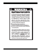
Engine exhaust and some of its constituents, and some dust created by power sanding, sawing, grinding, drillingandotherconstructionactivities contains chemicals known to the State of California to cause cancer, birth defects and other reproductive harm. Some examples of these chemicals are: Leadfromlead-basedpaints. Crystallinesilicafrombricks. Cementandothermasonryproducts. Arsenicandchromiumfromchemically treatedlumber.
G-55H GASOLINE VIBRATOR — TABLE OF CONTENTS G-55H GASOLINE VIBRATOR Honda GX160K1QX2 Engine Proposition 65 Warning ..................................................... 2 Table Of Contents ............................................................. 3 Parts Ordering Procedures ............................................... 4 Specifications ................................................................... 5 Safety Message Alert Symbols .................................... 6-7 Rules For Safe Operation .
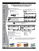
www.multiquip.com PARTS ORDERING PROCEDURES Ordering parts has never been easier! Choose from three easy options: Best Deal! Order via Internet (Dealers Only): If you have an MQ Account, to obtain a Username and Password, E-mail us at: parts@multiquip.com. Order parts on-line using Multiquip’s SmartEquip website! ■ View Parts Diagrams ■ Order Parts ■ Print Specification Information To obtain an MQ Account, contact your District Sales Manager for more information.
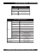
G-55H GASOLINE VIBRATOR — SPECIFICATIONS TABLE 1. G55H SPECIFICATIONS Vibrator Shaft Speed 10,600 RPMs @ 3600 Engine RPMs Power Unit Dimensions (L x W x H) Weight w/ Engine 24 x 20 x 18 in. (61 x 51 x 46 cm.) 77 Lbs. (35 Kg) TABLE 2. ENGINE SPECIFICATIONS Model HONDA GX160K1QX2 Type 4-stroke, Overhead valve, Single Cylinder Bore X Stroke 2.7 in. X 1.8 in. (68 mm x 45 mm) Displacement 9.9 cu. in. (163 cc) Max Output Engine Fuel Tank Capacity Approx. 0.95 U.S. Gallons (3.
G-55H GASOLINE VIBRATOR — SAFETY MESSAGE ALERT SYMBOLS FOR YOUR SAFETY AND THE SAFETY OF OTHERS! Safety precautions should be followed at all times when operating this equipment. Failure to read and understand the Safety Messages and Operating Instructions could result in injury to yourself and others. This Owner's Manual has been developed to provide complete NOTE instructions for the safe and efficient operation of the G-55H Gasoline Vibrator.
G-55H GASOLINE VIBRATOR — SAFETY MESSAGE ALERT SYMBOLS CAUTION Rotating Parts Hazards NEVER operate equipment with covers, or guards removed. Keep fingers, hands, hair and clothing away from all moving parts to prevent injury. CAUTION CAUTION Equipment Damage Hazards Other important messages are provided throughout this manual to help prevent damage to your equipment, other property, or the surrounding environment. Accidental Starting Hazards ALWAYS place the ON/OFF switch in the OFF position.
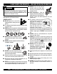
G-55H GASOLINE VIBRATOR — RULES FOR SAFE OPERATION DANGER Read this manual! Failure to follow instructions in this manual may lead to serious injury or even death! This equipment is to be operated by trained and qualified personnel only! This equipment is for industrial use only. The following safety guidelines should always be used when operating the G-55H Gasoline Vibrator: GENERAL SAFETY ■ DO NOT operate or service this equipment before reading this entire manual.
G-55H GASOLINE VIBRATOR — RULES FOR SAFE OPERATION ■ ALWAYS stop the engine before servicing, adding fuel and oil. ■ NEVER run engine without air filter. Severe engine damage may occur. ■ ALWAYS service air cleaner frequently to prevent carburetor malfunction. ■ ALWAYS be sure the operator is familiar with proper safety precautions and operations techniques before using. ■ ALWAYS store equipment properly when it is not being used.
G-55H GASOLINE VIBRATOR — OPERATION AND SAFETY DECALS Operation And Safety Decals The MQ/STOW G-55H Gasoline Vibrator is equipped with a number of operation and safety decals (Figure 1). These decals are provided for operator safety and maintenance information. Should any of these decals become unreadable, replacements can be obtained from your dealer. Figure 1. Operation and Safety Decals PAGE 10 — G-55H GASOLINE VIBRATOR — OPERATION & PARTS MANUAL — REV.
G-55H GASOLINE VIBRATOR — GENERAL INFORMATION General Information The G-55H Gasoline Vibrator employs a 5.5 HP Honda engine. It comes standard with a quick-disconnect coupling and an eccentric belt tensioner. The G-55H power unit utilizes a sturdy frame which enables the engine to operate in a 360° rotation. When operating the vibrator always wear rubber insulated gloves and boots. Safety glasses are also recommended.
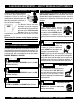
G-55H GASOLINE VIBRATOR — MAJOR COMPONENTS Figure 2. G-55H Gasoline Vibrator Components Figure 2 shows the location of the components and general maintenance parts. The function of each component is described below: 1. Eccentric Bell End – Supports the spindle shaft and 5. Rear Belt Guard – Attaches to the V-belt housing and upper pulley which drives the vibration function of the prevents access to the pulleys or V-belts while the vibrator is running. DO NOT operate the vibrator with this cover G-55H.
G-55H GASOLINE VIBRATOR — ENGINE COMPONENTS 5.5 HP Honda Gasoline Engine The engine (Figure 3) must be checked for proper lubrication and filled with fuel prior to operation. Refer to the manufacturer's engine manual for instructions & details of operation and servicing. The engine shown above is a HONDA engine. Operation for other types of engines may vary. 1. Fuel Filler Cap – Remove this cap to add unleaded gasoline to the fuel tank. Make sure cap is tightened securely. DO NOT over fill.
G-55H GASOLINE VIBRATOR — INSPECTION Inspection & Maintenance Saftey NEVER place hands or feet inside the belt guard cover while the engine is running. ALWAYS shut the engine down before performing any kind of maintenance service on the unit. CAUTION CAUTION Eyesight and Hearing Protection ALWAYS wear approved eye and hearing protection before inspecting, operating or servicing the vibrator.
G-55H GASOLINE VIBRATOR — INSPECTION WARNING Explosive Fuel Hazards Gasoline is extremely flammable, and its vapors can cause an explosion if ignited. DO NOT start the engine near spilled fuel or combustible fluids. DO NOT fill the fuel tank while the engine is running or hot. DO NOT overfill tank, since spilled fuel could ignite if it comes into contact with hot engine parts or sparks from the ignition system. Store fuel in approved containers, in well-ventilated areas and away from sparks and flames. 1.
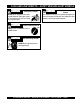
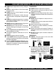
G-55H GASOLINE VIBRATOR — START-UP PROCEDURES This section is intended to assist the operator with initial start-up. It is extremely important that this section be read carefully before attempting to use the vibrator in the field. DO NOT use your vibrator until this section is thoroughly understood. WARNING 3. Place the engine choke lever (Figure 8) in the CLOSED position if starting a cold engine. Place the choke lever in the OPEN position if starting a warm engine or the temperature is warm.
G-55H GASOLINE VIBRATOR — START-UP/SHUTDOWN PROCEDURES 7. If the engine has started, slowly return the choke lever (Figure 6) to the OPEN position. If the engine has not started repeat steps 1 through 6. 8. Before the vibrator is placed into operation, immerse the vibrator head into the concrete and run the engine for several minutes. Check for fuel leaks, and noises that would associate with a loose V-belt cover or component. Stopping The Engine 1.
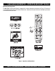
G-55H GASOLINE VIBRATOR — OPERATION Connecting the 382V Flexible Shaft Operation Read all the safety instructions carefully. Safety instructions 1. Connect the 382V Flexible Shaft to the Quick Disconnect coupling (Figure 13). will be found throughout this manual and on the vibrator motor. Keep all safety information available, accessible, and in good, 2. Pull UP on the lock pin and slide the shaft and quick readable condition. disconnect assembly into the eccentric end bell and release the lock pin.
G-55H GASOLINE VIBRATOR — OPERATION 1. Start the engine as previously described and procede to insert the vibrator head into the concrete. 2. The concrete is normally placed into the forms in layers about 12 to 18 inches thick in a manner which forms a fairly level surface. The vibrator head is inserted vertically into the top of the pile. Use the flexible shaft in as straight a position as possible and do not bend the flexible shaft sharply at any point.
G-55H GASOLINE VIBRATOR — MAINTENANCE Maintenance Instructions To receive trouble-free service from your G-55H gasoline vibrator, follow these instructions, as well as the instructions contained in the engine operating manual, flexible shaft operations manual and the vibrator head operations manual. The 382V flexible shafting requires cleaning and lubrication every 100 hours of operation. Refer to the flexible shaft operation and parts manual for maintenance instructions.
G-55H GASOLINE VIBRATOR — MAINTENANCE Engine Air Cleaner V-Belt Tension 1. Remove the air cleaner cover and foam filter element as shown in Figure 26. The belt can be tightened by rotating the eccentric countershaft assembly clockwise. When the belts are properly tensioned, they should deflect approximately 5 to 10mm when 5-10 pounds of force is applied centrally between the pulleys. Lock the countershaft in place with the locking screw and wing nut. 2.
G-55H GASOLINE VIBRATOR — TROUBLESHOOTING (ENGINE) TABLE 5. TROUBLESHOOTING (ENGINE) SYMPTOM Difficult to star t, "fuel is available, but no SPARK at spark plug". Difficult to star t, "fuel is available, and SPARK is present at the spark plug". Difficult to star t, "fuel is available, spark is present and compression is normal". Difficult to star t, "fuel is available, spark is present and compression is low". POSSIBLE CAUSE SOLUTION Spark plug bridging? Check gap, insulation or replace spark plug.
NOTE PAGE G-55H GASOLINE VIBRATOR — OPERATION & PARTS MANUAL — REV.
G-55H VIBRATOR — EXPLANATION OF CODE IN REMARKS COLUMN The following section explains the different symbols and remarks used in the Parts section of this manual. Use the help numbers found on the back page of the manual if there are any questions. The contents and part numbers listed in the parts section are subject to change without notice. Multiquip does not guarantee the availibility of the parts listed. Sample Parts List: NO.
G-55H GASOLINE VIBRATOR — SPARE PARTS G-55H GASOLINE VIBRATOR 1 TO 3 UNITS W/HONDA GX160K1QX2 ENGINE Qty. P/N Description 3 ............ 9807956846 .......... SPARK PLUG 3 ............ 17210ZE2505 ....... ELEMENT, AIR CLEANER 1 ............ 28462ZE2W11 ...... ROPE STARTER 1 ............ 17620ZH7023 ....... CAP, W/GASKET FUEL FILLER 4 ............ 16052 .................... V-BELT 3VX335 G-55H GASOLINE VIBRATOR — OPERATION & PARTS MANUAL — REV.
G-55H GASOLINE VIBRATOR — NAMEPLATE AND DECALS NAMEPLATE AND DECALS. PAGE 26 — G-55H GASOLINE VIBRATOR — OPERATION & PARTS MANUAL — REV.
G-55H GASOLINE VIBRATOR — NAMEPLATE AND DECALS NAMEPLATE AND DECALS. NO. PART NO. PART NAME 1 36521 DECAL, G-55H 1 2 11247 DECAL, HELMET, BOOT, GLOVES (ISO BLACK) 1 3 11246 DECAL, LIFT POINT ................................................. 2 ............ PART OF DECAL KIT 11246 4 11246 DECAL, HOT SURFACE ........................................... 1 ............ PART OF DECAL KIT 11246 5 NAMEPLATE ............................................................. 1 ............ CONTACT MQ PARTS DEPT.
G-55H GASOLINE VIBRATOR — ECCENTRIC/BODY ASSY. ECCENTRIC/BODY ASSY. PAGE 28 — G-55H GASOLINE VIBRATOR — OPERATION & PARTS MANUAL — REV.
G-55H GASOLINE VIBRATOR — ECCENTRIC/BODY ASSY. ECCENTRIC/BODY ASSY. NO 1 2 3# 4# 5# 6# 7# 8# 9# 10# 11# 12# 13# 14 15 16 17 18 19 20# 21 22 23 24 25# 26 27 PART NO 36248 18045-501 25015-501 08752-275 06330-002 14043-017 14546-001 08601-045 08751-156 06467-062 584013 2037 20875 22538-001 25845-001 18024-001 0202 0106 36517 18044-001 36516 16052 0627 25846-001 11534-018 27100-351 1386 PART NAME QTY. REMARK COUPLING, SHAFT 1 ECCENTRIC ASSY. ............................................. 1...............
G-55H GASOLINE VIBRATOR — PIVOT ASSY. PIVOT ASSY. PAGE 30 — G-55H GASOLINE VIBRATOR — OPERATION & PARTS MANUAL — REV.
G-55H GASOLINE VIBRATOR — PIVOT ASSY. PIVOT ASSY. NO PART NO PART NAME 1 2 3 4 5 6 7 5283 0300 B 0105 27108-351 2621 3264 07028-057 NUT - GRIPCO 5/16 - 18 FLATWASHER 5/16 HHCS 5/16 - 18 x 1 1/2 ENGINE PLATE - PIVOT GREASE FITTING FLATWASHER 1" COTTER PIN 5/32" x 1-1/2 QTY. REMARK 4 4 4 1 1 2 1 G-55H GASOLINE VIBRATOR — OPERATION & PARTS MANUAL — REV.
HONDA GX160K1QX2 ENGINE — AIR CLEANER ASSY. AIR CLEANER ASSY. PAGE 32 — G-55H GASOLINE VIBRATOR — OPERATION & PARTS MANUAL — REV.
HONDA GX160K1QX2 ENGINE — AIR CLEANER ASSY. AIR CLEANER ASSY. NO. 1 2 3 4 5 6 7 8 9 11 12 13 PART NO.
HONDA GX160K1QX2 ENGINE — CAMSHAFT ASSY. CAMSHAFT ASSY. PAGE 34 — G-55H GASOLINE VIBRATOR — OPERATION & PARTS MANUAL — REV.
HONDA GX160K1QX2 ENGINE — CAMSHAFT ASSY. CAMSHAFT ASSY. NO. 1 2 3 4 5 6 7 8 9 10 11 12 13 14 15 PART NO.
HONDA GX160K1QX2 ENGINE — CARBURETOR ASSY. CARBURETOR ASSY. PAGE 36 — G-55H GASOLINE VIBRATOR — OPERATION & PARTS MANUAL — REV.
HONDA GX160K1QX2 ENGINE — CARBURETOR ASSY. CARBURETOR ASSY. NO. 1 #+% * 2 * 3 4 * 5 * 6 # * 7 * 8 * 9 10 * 11 * 12 * 13 14 15 16 17 18 * 19 20 * 21 * 22 * 23 * 24$ 25 * 25 * 26 * PART NO.
HONDA GX160K1QX2 ENGINE — CONTROL ASSY. CONTROL ASSY. PAGE 38 — G-55H GASOLINE VIBRATOR — OPERATION & PARTS MANUAL — REV.
HONDA GX160K1QX2 ENGINE — CONTROL ASSY. CONTROL ASSY. NO. 2 4 5 6 7 8 * 9 * 10 * 11 * 12 * 13 * 14 * 15 * 17 18 19 * 22 * 23 * 24 PART NO. 16500ZH8823 16551ZE0010 16555ZE1000 16561ZE1020 16562ZE1020 16571ZH8020 16574ZE1000 16575ZH8000 16576891000 16578ZE1000 16580ZH8812 16584883300 16592ZE1810 90013883000 90016ZE5010 90114SA0000 93500050250H 938930501600 9405006000 PART NAME QTY. REMARKS CONTROL ASSEMBLY, REMOTE......................... 1............
HONDA GX160K1QX2 ENGINE — CRANKCASE COVER ASSY. CRANKCASE COVER ASSY. PAGE 40 — G-55H GASOLINE VIBRATOR — OPERATION & PARTS MANUAL — REV.
HONDA GX160K1QX2 ENGINE — CRANKCASE COVER ASSY. CRANKCASE COVER ASSY. NO. 1 3 4 5 9 10 11 * 12 13 14 * PART NO. 11300ZE1641 11381ZH8801 15600ZE1003 15600ZG4003 15625ZE1003 15625ZE1003 91202883005 9430108140 957010803200 961006205000 PART NAME QTY. REMARKS COVER ASSEMBLY, CRANKCASE (U- TYPE) ..... 1 ...........
HONDA GX160K1QX2 ENGINE — CRANKSHAFT/BALANCER ASSY. CRANKSHAFT /BALANCER WEIGHT ASSY. PAGE 42 — G-55H GASOLINE VIBRATOR — OPERATION & PARTS MANUAL — REV.
HONDA GX160K1QX2 ENGINE — CRANKSHAFT/BALANCER ASSY. CRANKSHAFT ASSY. NO. 3 9 PART NO. 13310ZE1601 90745ZE1600 PART NAME CRANKSHAFT, Q- TYPE KEY, 4.78 X 4,78 X 38 QTY. 1 1 REMARKS G-55H GASOLINE VIBRATOR — OPERATION & PARTS MANUAL — REV.
HONDA GX160K1QX2 ENGINE — CYLINDER BARREL ASSY. CYLINDER BARREL ASSY. PAGE 44 — G-55H GASOLINE VIBRATOR — OPERATION & PARTS MANUAL — REV.
HONDA GX160K1QX2 ENGINE — CYLINDER BARREL ASSY. CYLINDER BARREL ASSY. NO. 2 3 4 * 5 # * 6 # * 8 * 9 10 11 * 12 13 * 14% 15% 16 17 18 * 19 20 PART NO. 12000ZH8811 15510ZE1033 16510ZE1000 16511ZE1000 16512ZE1000 16531ZE1000 16541ZE1000 90131ZE1000 80451ZE1000 90601ZE1000 90602ZE1000 91001ZF1003 91202883005 91353671003 9405010000 9410106800 9425108000 957010601200 PART NAME QTY. REMARKS CYLINDER ASSEMBLY, OIL ALERT .................... 1............ INCLUDES ITEMS W/ * SWITCH ASSEMBLY, OIL LEVEL ............
HONDA GX160K1QX2 ENGINE — CYLINDER HEAD ASSY. CYLINDER HEAD ASSY. PAGE 46 — G-55H GASOLINE VIBRATOR — OPERATION & PARTS MANUAL — REV.
HONDA GX160K1QX2 ENGINE — CYLINDER HEAD ASSY. CYLINDER HEAD ASSY. NO. 1 2 * 3 * 4% 5 6 7 8 9 10 11 12 14 15 PART NO. 12210ZH8000 12204ZE1306 12205ZE1315 12216ZE5300 12251ZF1800 12310ZE1010 12391ZE1000 15721ZH8000 90016ZE1000 90043ZE1020 90047ZE1000 9430110160 957230806000 9807956846 PART NAME QTY. REMARKS CYLINDER HEAD .................................................. 1............ INCLUDES ITEMS W/ * GUIDE, VALVE OS (OPTIONAL 1 GUIDE, EXHAUST VALVE OS (OPTIONAL) ......... 1............
HONDA GX160K1QX2 ENGINE — FAN COVER ASSY. FAN COVER ASSY. PAGE 48 — G-55H GASOLINE VIBRATOR — OPERATION & PARTS MANUAL — REV.
HONDA GX160K1QX2 ENGINE — FAN COVER ASSY. FAN COVER ASSY. NO. 2 4 7 8 10 11 13 14 17 19 PART NO. 19610ZE1000ZC 19611ZH8810 90601ZH7013 19630ZH8000 32197ZH8003 36100ZE1015 90013883000 90022888010 34150ZH7003 957010600800 PART NAME COVER, FAN "NH1" (BLACK) PLATE, SIDE (OIL ALERT) CLIP, HARNESS SHROUD SUB- HARNESS SWITCH ASSEMBLY, ENGINE STOP BOLT, FLANGE 6 X12 (CT200) BOLT, FLANGE 6 X20 (CT200) ALERT UNIT, OIL BOLT, FLANGE 6 X8 QTY.
HONDA GX160K1QX2 ENGINE — FLYWHEEL ASSY. FLYWHEEL ASSY. PAGE 50 — G-55H GASOLINE VIBRATOR — OPERATION & PARTS MANUAL — REV.
HONDA GX160K1QX2 ENGINE — FLYWHEEL ASSY. FLYWHEEL ASSY. NO. 1 2 4 5 5 8 PART NO. 13331357000 19511ZE1000 28451ZH8003 31100ZE1010 31100ZE1810 90201878003 PART NAME KEY, SPECIAL WOODRUFF (25 X18) FAN, COOLING PULLEY, STARTER FLYWHEEL FLYWHEEL, LAMP NUT, SPECIAL 14MM QTY. 1 1 1 1 1 1 REMARKS G-55H GASOLINE VIBRATOR — OPERATION & PARTS MANUAL — REV.
HONDA GX160K1QX2 ENGINE — FUEL TANK ASSY. FUEL TANK ASSY. PAGE 52 — G-55H GASOLINE VIBRATOR — OPERATION & PARTS MANUAL — REV.
HONDA GX160K1QX2 ENGINE — FUEL TANK ASSY. FUEL TANK ASSY. NO. 1 2 3 3 5 6 * 11 12 13 14 15 PART NO. 16854ZH8000 16955ZE1000 17510ZE1020ZB 17510ZE1020ZF 17620ZH7023 17631ZH7003 91353671003 9405006000 950014500360M 9500202080 957010602500 PART NAME QTY. REMARKS RUBBER, SUPPORTER 107MM 1 JOINT, FUEL TANK 1 TANK, FUEL *R8* (BRIGHT RED) 1 TANK, FUEL *NH1* (BLACK) 1 CAP, FUEL FILLER ............................................... 1 ........... INCLUDES ITEM W/ * GASKET, FUEL FILLER CAP 1 O- RING 13.5 X1.
HONDA GX160K1QX2 ENGINE — IGNITION COIL ASSY. IGNITION COIL ASSY. PAGE 54 — G-55H GASOLINE VIBRATOR — OPERATION & PARTS MANUAL — REV.
HONDA GX160K1QX2 ENGINE — IGNITION COIL ASSY. IGNITION COIL ASSY. NO. 1 2 7 11 PART NO. 30500ZE1033 30700ZE1013 36101ZE1010 90121952000 PART NAME COIL ASSEMBLY, IGNITION CAP ASSEMBLY, NOISE SUPPRESSOR WIRE, STOP SWITCH 370MM BOLT, FLANGE 6 X25 QTY. 1 1 1 2 REMARKS G-55H GASOLINE VIBRATOR — OPERATION & PARTS MANUAL — REV.
HONDA GX160K1QX2 ENGINE — MUFFLER ASSY. MUFFLER ASSY. PAGE 56 — G-55H GASOLINE VIBRATOR — OPERATION & PARTS MANUAL — REV.
HONDA GX160K1QX2 ENGINE — MUFFLER ASSY. MUFFLER ASSY. NO. 1 1 3 7 8 11 12 15 PART NO. 18310ZF1000 18310ZH8810 18320ZF1H01 18355ZE1000 18381ZH8800 90050ZE1000 90055ZE1000 94001080000S PART NAME MUFFLER MUFFLER (OPTIONAL) PROTECTOR, MUFFLER ARRESTER, SPARK (OPTIONAL) GASKET, MUFFLER SCREW, TAPPING 5 X 8 (OPTIONAL SCREW, TAPPING 4 X 6 (OPTIONAL) NUT, HEX. 8MM QTY. 1 1 1 1 1 4 1 2 REMARKS G-55H GASOLINE VIBRATOR — OPERATION & PARTS MANUAL — REV.
HONDA GX160K1QX2 ENGINE — PISTON ASSY. PISTON ASSY. PAGE 58 — G-55H GASOLINE VIBRATOR — OPERATION & PARTS MANUAL — REV.
HONDA GX160K1QX2 ENGINE — PISTON ASSY. PISTON ASSY. NO. 1 1 1 1 2 2 2 2 3 4 4 5 6 PART NO. 13010ZH8941 13011ZH8941 13012ZH8941 13013ZH8941 13101ZH8000 13102ZH8000 13103ZH8000 13104ZH8000 13111ZE1000 132AOZE1000 13200ZE1010 90001ZE1000 90551ZE1000 PART NAME RING SET, PISTON (STANDARD) RING SET, PISTON (OS 0.25), OPTIONAL RING SET, PISTON (OS 0.50), OPTIONAL RING SET, PISTON (0.75), OPTIONAL PISTON (STANDARD) PISTON (OS 0.25), OPTIONAL PISTON (OS 0.50), OPTIONAL PISTON (0.75), OPTIONAL PIN, PISTON ROD ASSY.
HONDA GX160K1QX2 ENGINE — RECOIL STARTER ASSY. RECOIL STARTER ASSY. PAGE 60 — G-55H GASOLINE VIBRATOR — OPERATION & PARTS MANUAL — REV.
HONDA GX160K1QX2 ENGINE — RECOIL STARTER ASSY. RECOIL STARTER ASSY. NO. 1 2 * 3 * 4 * 5 * 6 * 7 * 8 * 9 * 10 * 11 * 12 PART NO. 28400ZH8013ZB 28410ZH8003ZB 28420ZH8013 28422ZH8013 28433ZH8003 28441ZH8003 28442ZH8003 28443ZH8003 28461ZH8003 28462ZH8003 90003ZH8003 90008ZE2003 PART NAME QTY. REMARKS STARTER ASSY., RECOIL "NH1" BLACK ...................1 ............
HONDA GX160K1QX2 ENGINE — GASKET KIT ASSY. NO ARTWORK AVAILABLE PAGE 62 — G-55H GASOLINE VIBRATOR — OPERATION & PARTS MANUAL — REV.
HONDA GX160K1QX2 ENGINE — GASKET KIT ASSY. GASKET KIT ASSY. NO. 1 * 2 * 3 * 4 * 5 * 6 * PART NO. 06111ZH8405 11381ZH8801 12251ZF1800 12391ZE1000 16212ZH8800 16221ZH8801 18381ZH8800 PART NAME QTY. REMARKS GASKET KIT ......................................................... 1............
HONDA GX160K1QX2 ENGINE — LABELS ASSY. L ABELS ASSY. PAGE 64 — G-55H GASOLINE VIBRATOR — OPERATION & PARTS MANUAL — REV.
HONDA GX160K1QX2 ENGINE — LABELS ASSY. ENGINE LABELS ASSY. NO. 1 2 3 6 7 8 15 PART NO. 87521ZH8020 87522ZE1810 87522ZH9000 87528ZE1810 87530ZH8810 87532ZH8810 887586ZH7W00 PART NAME ENBLEM 5.5 MARK, CAUTION (EXTERNAL) LABEL, CAUTION MARK, CHOKE LABEL, SPECIFICATION (EXTERNAL) MARK, OIL ALERT (E) LABEL, FUEL CAUTION QTY. 1 1 1 1 1 1 1 REMARKS G-55H GASOLINE VIBRATOR — OPERATION & PARTS MANUAL — REV.
Effective: July 15, 2003 PAYMENT TERMS TERMS AND CONDITIONS OF SALE — PARTS 5. Parts must be in new and resalable condition, in the original Multiquip package (if any), and with Multiquip part numbers clearly marked. 6. The following items are not returnable: Terms of payment for parts are net 30 days. FREIGHT POLICY All parts orders will be shipped collect or prepaid with the charges added to the invoice. All shipments are F.O.B. point of origin.
NOTE PAGE G-55H GASOLINE VIBRATOR — OPERATION & PARTS MANUAL — REV.
OPERATION AND PARTS MANUAL HERE'S HOW TO GET HELP PLEASE HAVE THE MODEL AND SERIAL NUMBER ON-HAND WHEN CALLING UNITED STATES Multiquip Corporate Office 18910 Wilmington Ave. Carson, CA 90746 Contact: mq@multiquip.com Mayco Parts 800-306-2926 310-537-3700 Service Department 800-421-1244 310-537-3700 Tel.