OPERATION MANUAL NIGHTHAWK SERIES MODEL LT12D50SA DEDICATED LIGHT TOWER (LOMBARDINI LDW 1003 DIESEL ENGINE) Revision #0 (03/16/09) To find the latest revision of this publication, visit our website at: www.multiquip.com THIS MANUAL MUST ACCOMPANY THE EQUIPMENT AT ALL TIMES.
TABLE OF CONTENTS LT12D50SA Light Tower Table Of Contents .................................................... 2 Safety Information .............................................. 3-10 Lamp Footcandle Plot............................................ 11 Specifications ................................................... 12-13 Dimensions ............................................................ 14 General Information ............................................... 15 Components .............................
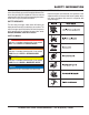
SAFETY INFORMATION Do not operate or service the equipment before reading the entire manual. Safety precautions should be followed at all times when operating this equipment. Failure to read and understand the safety messages and operating instructions could result in injury to yourself and others. SAFETY SYMBOLS Potential hazards associated with the operation of this equipment will be referenced with hazard symbols which may appear throughout this manual in conjunction with safety messages.
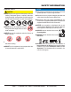
SAFETY INFORMATION GENERAL SAFETY CAUTION NEVER operate this equipment without proper protective clothing, shatterproof glasses, respiratory protection, hearing protection, steel-toed boots and other protective devices required by the job or city and state regulations. NEVER operate this equipment when not feeling well due to fatigue, illness or when under medication. NEVER operate this equipment under the influence of drugs or alcohol.
SAFETY INFORMATION LIGHT TOWER SAFETY DANGER NEVER use light tower in rain, snow, or areas of high humidity that could generate electrical storms. NEVER operate the equipment in an explosive atmosphere or near combustible materials. An explosion or fire could result causing severe bodily harm or even death. WARNING NEVER disconnect any emergency or safety devices. These devices are intended for operator safety. Disconnection of these devices can cause severe injury, bodily harm or even death.
SAFETY INFORMATION ENGINE SAFETY NOTICE DANGER The engine fuel exhaust gases contain poisonous carbon monoxide. This gas is colorless and odorless, and can cause death if inhaled. The engine of this equipment requires an adequate free flow of cooling air. NEVER operate this equipment in any enclosed or narrow area where free flow of the air is restricted. If the air flow is restricted it will cause injury to people and property and serious damage to the equipment or engine.
SAFETY INFORMATION FUEL SAFETY DANGER DO NOT start the engine near spilled fuel or combustible fluids. Diesel fuel is extremely flammable and its vapors can cause an explosion if ignited. ALWAYS refuel in a well-ventilated area, away from sparks and open flames. ALWAYS use extreme caution when working with flammable liquids. DO NOT fill the fuel tank while the engine is running or hot.
SAFETY INFORMATION If lifting through pockets, make sure forks of forklift are inserted in pockets as far as possible before lifting. TRANSPORTING SAFETY CAUTION Before lifting, make sure that light tower parts are not damaged and screws are not loosened or lost. ALWAYS make sure crane or lifting device has been properly secured to lifting hook of the equipment. NEVER lift the equipment while engine is running. Make sure the tower is in the stowed position before lifting.
SAFETY INFORMATION ELECTRICAL SAFETY DANGER The electrical voltage required to operate the generator can cause severe injury or even death through physical contact with live circuits. Turn generator and all circuit breakers OFF before performing maintenance on the generator. NEVER insert any objects into the output receptacles during operation. This is extremely dangerous. The possibility exists of electrical shock, electrocution or death.
SAFETY INFORMATION BATTERY SAFETY DANGER DO NOT drop the battery. There is a possibility that the battery will explode. DO NOT expose the battery to open flames, sparks, cigarettes, etc. The battery contains combustible gases and liquids. If these gases and liquids come into contact with a flame or spark, an explosion could occur. ENVIRONMENTAL SAFETY NOTICE Dispose of hazardous waste properly. Examples of potentially hazardous waste are used motor oil, fuel and fuel filters.
LAMP FOOTCANDLE PLOT Figure 1. Lamp Footcandle Plot LT12D50SA LIGHT TOWER • OPERATION MANUAL — REV.
SPECIFICATIONS Table 1. LT12D50SA Specifications Light Tower Model LT12D50SA Engine Model Lombardini LDW 1003 Diesel Engine Weight (Dry) 1,550 lbs. (700 kg.) Support Points Wind Stability with Genset 5 65 mph (80.46 kph) Lamps Four 1,000-Watt Metal Halide Lumens 440,000 Light Coverage Light Termination 5 to 7 acres 4 x 3-pin QD plug Generator Specifications Twist-Lock Circuit Breaker (Amps) 30 A Continuous Output (Watts) 6,000 W Noise Level @ 23 ft.
SPECIFICATIONS Table 2. Engine Specifications Engine Type 3-cylinder, Diesel Engine Displacement 62.73 cu. in. (1028 cc) Max Output Standby 11 H.P. at 1,500 R.P.M. Fuel Tank Capacity Approx. 30 U.S. Gallons (113 Liters) Run Time With 4 Lights Standard Idle Speed Lombardini LDW 1003 Diesel Engine Fuel Type Oil Sump Capacity 64 Hours 1,500 R.P.M. N0. 2 Diesel Fuel 2.64 U.S. Quarts (2.5 Liters) Cooling System Liquid-cooled Coolant Capacity 5.18 U.S. Quarts (4.
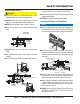
DIMENSIONS DEPLOYED POSITION C STOWED POSITION D E F B A RIGHT SIDE G REAR Figure 2. Dimensions Table 3. Dimensions Reference Letter Description Dimension A Length (Mast Stowed Position) 170 in. (431 cm.) B Length (Mast Deployed Position) 101 in. (256 cm.) C Max. Height (Mast Deployed Position) 31.5 ft. (9.6 m) D Height (Mast Stowed Position) 74 in. (187 cm.) E Ground Clearance (From Axle) 8 in. (20 cm.) F Width (Tow Ready) 51 in. (129 cm.
GENERAL INFORMATION The Multiquip LT12D50SA Light Tower is a dedicated general purpose light tower engineered to provide dependable lighting for a wide range of applications. This includes lighting for construction sites, industrial locations, special events, and emergency conditions. PANEL LIGHT METAL HALIDE LAMPS CONVENIENCE RECEPTACLE PLATES The lighting system of the LT12D50SA Light Tower is comprised of 4 metal halide, 1000-watt lamps.
COMPONENTS 1 4 2 5 7 9 3 6 17 15 14 13 16 10 18 12 8 18 11 Figure 3. Major Components (Control Panel Side) Figures 3 and 4 show the location of the controls and components for the LT12D50SA light tower. The function of each control is described below. 1. Mast Rotation Locking Knob — Unscrew this knob to release mast for rotation. Tighten this knob to lock mast after it is set to the desired position. 2. Mast Extension Winch — Use this winch to extend the mast to the desired height.
COMPONENTS 19 24 23 25 20 21 22 REAR VIEW FRONT VIEW Figure 4. Major Components (Front/Rear) 14. Safety Chain — Always attach safety chain to the towing vehicle. Never tow the light tower with the safety chain unattached. 15. Ball Hitch Coupler — Attach this coupler to the towing vehicle. Use only the specified ball diameter as indicated on your coupler. Use of any other ball diameter will create an extremely dangerous condition which can result in separation of the coupler and ball or ball failure.
CONTROL PANEL 1 2 5 4 240 VAC/30A MAIN BREAKER 120 VAC/15A GFCI BREAKER 12 6 LIGHT CONTROL/BREAKER 8 10 LOMBARDINI 9 13 7 3 11 = NOT USED Figure 5. Controls and Indicators PAGE 18 — LT12D50SA LIGHT TOWER • OPERATION MANUAL — REV.
CONTROL PANEL Figure 5 shows the location of the controls and indicators on the control panel for the different engines used with the LT12 light tower. Service the equipment as needed depending on the alarm indicated. Below is a brief explanation of each control or indicator. 1. Internal Cabinet Light Switch — This switch controls the internal cabinet light for the light tower control panel. When the cabinet door is raised, the light will automatically come on.
INSPECTION BEFORE STARTING 1. Read all safety instructions at the beginning of manual. on the dipstick. Verify that the oil level is maintained between the two notches as shown in Figure 6. Always fill with recommended type oil as listed in Table 4. See Table 2 for engine oil capacity. 2. Clean the light tower, removing dirt and dust, particularly the engine cooling air inlet and air cleaner. 3. Check the air filter for dirt and dust. If air filter is dirty, replace air filter with a new one as required.
INSPECTION 1. To check the engine fuel level, make sure the light tower is placed on secure level ground with the engine stopped. The 12-volt DC battery (Figure 8) is shipped dry and will require a proper electrolyte level for operation. 2. Lift the light tower access door (Figure 7) opposite the control panel. Set the door support latch in place to keep the door open (up). Figure 8.
INSPECTION COOLANT CLEANING THE RADIATOR It is recommended that antifreeze/summer coolant be used with the engine. This can be purchased pre-diluted or in concentrate and mixed with 50% demineralized water. See engine owner's manual for more details. The engine may overheat if the radiator fins become overloaded with dust or debris. Periodically clean the radiator fins with compressed air.
INSPECTION b. Locate the slot or key (A) on each female connector as shown in Figure 11. CAUTION NEVER start the engine with any circuit breakers in the ON position. Light tower is placed on secure level ground with chock blocks underneath each wheel to prevent the light tower from rolling. Outriggers have been fully extended to prevent the trailer from tipping. Light tower trailer support stands have been positioned properly and the trailer is level. Lamps have been adjusted to desired position.
OPERATION STARTING THE ENGINE MAST OPERATION 1. Open the access panel door on the right side of the light tower (opposite the fuel tank). Set the door latch in place to hold the door open (up). DANGER ALWAYS make sure the area above light tower is open and clear of overhead power lines and other obstructions. The tower extends in excess of 30 feet (9 meters). Contact with overhead power lines or other obstructions could result in equipment damage, serious injury or death! 2. Ensure all breakers are off.
OPERATION 2. As soon as the pin clears the travel position hole, release it and continue sliding out the outrigger. The pin must snap into the outrigger locking hole in the extended position. Lowering the Mast 3. After extending all outriggers, rotate all trailer jack stands into the foot down position, then turn the crank handle on the jackstands clockwise to lower it and level the light tower. 2. Continue turning the winch counterclockwise until the mast has been fully retracted (slack in the cable).
OPERATION RETAINING PIN MAST CRADLE SUPPORT CRADLE LOCK/ RELEASE PIN MAST EXTENSION WINCH VERTICAL MAST WINCH MAST LOCK/ RELEASE PIN MAST LOCK HANDLE MAST ROTATION HANDLES MAST ROTATION LOCKING KNOB ROTATING THE MAST Figure 16. Mast Operation PAGE 26 — LT12D50SA LIGHT TOWER • OPERATION MANUAL — REV.
OPERATION TURNING ON THE LAMPS AUXILIARY OUTPUT RECEPTACLES The main circuit breaker (30 amps), and 4 lamp circuit breakers (15 amps each) are located on the upper control panel (Figure17). The light tower is equipped with auxiliary output receptacle plates with wiring ready to install auxiliary receptacles (Figure 18). 1. Place the main circuit breaker (Figure 17) on the control panel to the ON position.
OPERATION NORMAL SHUTDOWN 1. If a load is attached to the generator of the light tower, remove the load. 2. Set the four lamp circuit breakers on the control panel to the OFF position. 3. Place the MAIN circuit breaker on the control panel to the OFF position. NOTICE Failure to turn the breakers off may damage the generator. 4. Wait a few seconds and observe that all four lamps are OFF. 5. Let the engine idle for a few minutes with no load. 6. Turn the ignition key to the OFF position.
MAINTENANCE BASIC INSPECTION AND MAINTENANCE See Table 7 below for a general inspection and maintenance checklist. For more detailed maintenance, refer to the engine service manual. Table 7.
MAINTENANCE GENERAL INSPECTION Service Daily Prior to each use, the light tower should be cleaned and inspected for deficiencies. Check for loose, missing or damaged nuts, bolts or other fasteners. Also check for fuel or oil leaks. If engine is operating in very dusty and dry grass conditions, a clogged air cleaner will result in high fuel consumption, loss of power and excessive carbon buildup in the combustion chamber.
MAINTENANCE 6. Adjust the flow of the water flowing in and draining out to ensure that the radiator is always full during the flushing operation. While flushing water through the system, make sure the water inlet hose does not come out of the radiator filler port. 7. After flushing, stop the engine, open drain plug and drain the water, then close drain plugs. 8. After draining the water, flush the system with a flushing agent. See instructions on flushing agent label. 9.
MAINTENANCE CHECK CABLE WEAR The wire rope (cable) that raises and extends the mast is a very important part of the light tower. There is one cable/ hand winch system, located on the tongue of the trailer, that raises and extends the light tower mast. There is a second cable/hand winch system located on the mast that serves to raise and lower the two extendable sections of the mast. DANGER Wire rope (cable) will fail if it is worn, frayed, misused, crushed, kinked or damaged in any way.
MAINTENANCE 6. Route the upper mast cable through the center mast pulley and connect the free end of the cable to the lower mast ankle shackle. Route the center mast cable through the lower mast pulley and connect the free end of the cable to the hand winch at the bottom of the lower mast. 7. Raise, extend, retract and lower the mast several times to verify correct operation. STORAGE For storage for over 30 days, the following is required: Fill the fuel tank completely.
MAINTENANCE — TRAILERS The following trailer maintenance guidelines are intended to assist the operator in preventive maintenance. ADJUSTABLE CHANNEL frequently, at least every six months and prior to use. Follow the steps below to disassemble the wheel hub and service the wheel bearings. See Figure 22. BEARING Your trailer may be equipped with an adjustable channel (Figure 21) that allows the coupler to be raised or lowered to a desired height.
MAINTENANCE — TRAILERS DANGER NEVER crawl under the trailer unless it is on firm and level ground and resting on properly placed and secured jackstands. The possibility exists of the trailer falling thus causing equipment damage and severe bodily harm even death! LEAF SUSPENSION The leaf suspension springs and associated components (Figure 23) should be visually inspected every 6,000 miles for signs of excessive wear, elongation of bolt holes, and loosening of fasteners.
TROUBLESHOOTING Practically all breakdowns can be prevented by proper handling and maintenance inspections, but in the event of a breakdown, please take remedial action following the diagnosis based on the troubleshooting tables. If the problem cannot be remedied, please leave the unit as is and consult Multiquip's technical support department or your local dealer.
TROUBLESHOOTING Table 9. Engine Troubleshooting Symptom Engine does not start. Starter does not run. Possible Cause Solution No fuel? Replenish fuel. Air in the fuel system? Bleed system. Water in the fuel system? Remove water from fuel tank. Fuel pipe clogged? Clean fuel pipe. Fuel filter clogged? Clean or change fuel filter. Excessively high viscosity of fuel or engine oil at low temperature? Use the specified fuel or engine oil. Fuel with low cetane number? Use the specified fuel.
TROUBLESHOOTING Table 9. Engine Troubleshooting (continued) Symptom Engine revolution is not smooth. Either white or blue exhaust gas is observed. Either black or dark gray exhaust gas is observed. Deficient output. Possible Cause Solution Fuel filter clogged or dirty? Clean or change. Air cleaner clogged? Clean or change. Fuel leak due to loose injection pipe retaining nut? Tighten nut. Injection pump malfunctioning? Repair or replace. Incorrect nozzle opening pressure? Adjust.
TROUBLESHOOTING Table 10. Lamp Troubleshooting Symptom Possible Cause Lamp Burned Out? Test the lamp in a fixture which is operating properly. Replace if necessary. Lamp Loose in Socket? Inspect lamp base to see if there is arcing at center contact button. Tighten lamp snugly. Check socket for damage. Replace if defective. Floodling Plugs Not Tight? Check plug and receptacle. Tighten if loose. Defective Ballast? Interchange ballast plugs in generator enclosure. If lamp starts, replace ballast.
TROUBLESHOOTING Table 10. Lamp Troubleshooting (continued) Symptom Possible Cause Solution Lamp starts slowly (ARC does not strike when switch is first turned on) Defective Lamp? Lamp may glow for extended period of time. Replace after checking voltage and ballast. Circuit breaker trips on lamp start-up Short Circuit or Ground? Check wiring against diagram. Check for shorts or ground. Normal Lamp Depreciation? Replace Lamp. Dirty Lamp or Fixture? Clean lamp and fixture.
TROUBLESHOOTING LAMP TROUBLESHOOTING GUIDE Starting Use the following procedure and wiring diagram on the next page to determine which of the four lamps is not functioning: 1. Start the generator and verify that there are no abnormal sounds. Connections 2. Turn CB1 thru CB4 circuit breakers to the ON position. 1. Make sure that lamp #1 power cable is plugged into the J1 connector on the T-Bar assembly. 3. Wait a few minutes and determine which lamp is not igniting. 2.
LT12D50SA WIRING DIAGRAM — S/N 902625 AND BELOW ROTOR STATOR BLACK 4 BLACK 3 ROTOR WINDINGS 230 VAC 50 HZ FIXED FLOW CURRENT DIODE STATOR WINDING BLACK 2 BLACK 1 EXCITATION WINDING WHT 50 HZ GRN 60 HZ BLK 1 RED 111111 22222 TB1 33333 C1 35µF@425V EXCITATION CAPACITOR 44444 RED 4 3 BLK BLK BLK BLK A B RED RED C1 5V 42 F@ N 35µ ITATIO R EXC ACITO P CA NOTES A USE ONLY 50 Hz GENERATOR, P/N 49126. B USE ONLY 35µF@425 EXCITATION CAPACITOR, P/N GECAP35MF.
LT12D50SA WIRING DIAGRAM — S/N 902625 AND BELOW NOTES: C WIRE SIZE IS 12 AWG UNLESS OTHERWISE SPECIFIED. J1 J2 BLK BLK WHT BLK WHT D J4 J3 BLK WHT WHT SOME UNITS MAY HAVE A 47KW ½ WATT RESISTOR INSTALLED ACROSS THE CAPACITOR TERMINALS. OTHER UNITS MAY HAVE THIS RESISTOR INTERNALLY INSTALLED WITHIN THE CAPACITOR. E CONNECT AUX. POWER RECEPTACLE TO THESE CONNECTION POINTS.
LT12D50SA WIRING DIAGRAM — S/N 902626 AND ABOVE ROTOR STATOR BLACK 4 BLACK 3 ROTOR WINDINGS 230 VAC 50 HZ FIXED FLOW CURRENT DIODE STATOR WINDING BLACK 2 BLACK 1 EXCITATION WINDING WHT 50 HZ GRN 60 HZ BLK 1 RED 111111 22222 TB1 33333 C1 35µF@425V EXCITATION CAPACITOR 44444 RED 4 3 BLK BLK BLK BLK A B RED RED C1 5V 42 F@ N 35µ ITATIO R EXC ACITO P CA NOTES A USE ONLY 50 Hz GENERATOR, P/N 49126. B USE ONLY 35µF@425 EXCITATION CAPACITOR, P/N GECAP35MF.
LT12D50SA WIRING DIAGRAM — S/N 902626 AND ABOVE NOTES: C WIRE SIZE IS 12 AWG UNLESS OTHERWISE SPECIFIED. J1 J2 BLK BLUE BRN RED BRN D J4 J3 YEL WHT WHT SOME UNITS MAY HAVE A 47KW ½ WATT RESISTOR INSTALLED ACROSS THE CAPACITOR TERMINALS. OTHER UNITS MAY HAVE THIS RESISTOR INTERNALLY INSTALLED WITHIN THE CAPACITOR. E CONNECT AUX. POWER RECEPTACLE TO THESE CONNECTION POINTS. GRN F 7-WIRE COIL CORD P/N 29433 REPLACES 6-WIRE COIL CORD P/N 19955 S/N 905513 AND ABOVE.
LOMBARDINI ENGINE WIRING DIAGRAM Operating voltage: 10 to 16 VDC (30VDC max 10 sec.) A B A B PAGE 46 — LT12D50SA LIGHT TOWER • OPERATION MANUAL — REV.
TRAILER GUIDELINES The following guidelines are intended to assist the operator in the operation and handling of a trailer. Shift your automatic transmission into a lower gear for city driving. Safety precautions should be followed at all times when operating a trailer. Failure to read, understand and follow the safety guidelines could result in injury to yourself and others. Loss of control of the trailer or tow vehicle can result in death or serious injury.
TRAILER GUIDELINES DRIVING CONDITIONS When towing a trailer, you will have decreased acceleration, increased stopping distance, and increased turning radius (which means you must make wider turns to keep from hitting curbs, vehicles, and anything else that is on the inside corner). In addition, you will need a longer distance to pass, due to slower acceleration and increased length. Be alert for slippery conditions.
TRAILER GUIDELINES INOPERABLE BRAKES, LIGHTS OR MIRRORS Be sure that the brakes and all of the lights on your trailer are functioning properly before towing your trailer. Check the trailer taillights by turning on your tow vehicle headlights. Check the trailer brake lights by having someone step on the tow vehicle brake pedal while you look at trailer lights. Do the same thing to check the turn signal lights. See Trailer Wiring Diagram section in this manual.
TRAILER GUIDELINES To determine the “empty” or “net” weight of your trailer, weigh it on an axle scale. To find the weight of the trailer using an axle scale, you must know the axle weights of your tow vehicle without the trailer coupled. Some of the trailer weight will be transferred from the trailer to the tow vehicle axles, and an axle scale weighs all axles, including the tow vehicle axles. VIN TAG VIN TAG Figure B.
TRAILER GUIDELINES SAFETY CHAINS If the coupler connection comes loose, the safety chains can keep the trailer attached to the tow vehicle. With properly rigged safety chains, it is possible to keep the tongue of the trailer from digging into the road pavement, even if the coupler-to-hitch connection comes apart. JACKSTAND A device on the trailer that is used to raise and lower the coupler. The jack is sometimes called the “landing gear” or the “tongue jack”.
TRAILER GUIDELINES WARNING Lower the trailer (Figure D) until the coupler fully engages the hitch ball. A worn, cracked or corroded hitch ball can fail while towing and may result in death or serious injury. 2-INCH TRAILER COUPLER TOW VEHICLE Before coupling trailer, inspect the hitch ball for wear, corrosion and cracks. Replace worn or damaged hitch ball. 2-INCH BALL WARNING A loose hitchball nut can result in uncoupling, leading to death or serious injury.
TRAILER GUIDELINES Attaching Safety Chain Backup Lights (place tow vehicle gear shift in reverse). Visually inspect the safety chains and hooks for wear or damage. Replace worn or damaged safety chains and hooks before towing. Turn Signals (activate tow vehicle directional signal lever). Attach the safety chains so that they: • Cross underneath the coupler. See Figure E.
TRAILER GUIDELINES PINTLE HITCH COUPLER A pintle eye coupler (Figure F) connects to a pintle-hook hitch that is located on or under the rear bumper of the tow vehicle. This system of coupling a trailer to a tow vehicle is sometimes referred to as a “lunette eye, tow ring or G.I. hitch.
TRAILER GUIDELINES Raise the bottom surface of the coupler to be above the top of the pintle hitch hook. Use the tongue jackstand to support the trailer tongue. Wood or concrete blocks may also be used. WARNING Lower the trailer so that its entire tongue weight is held by the hitch. Raise the jackstand to a height where it will not interfere with the road. TIRE SAFETY A defective pintle hitch not properly fastened can result in uncoupling, leading to death or serious injury.
TRAILER GUIDELINES wrench, use a lug wrench (from your tow vehicle) and tighten the nuts as much as you can. Then have a service garage or trailer dealer tighten the lug nuts to the proper torque. WARNING Metal creep between the wheel rim and lug nuts will cause rim to loosen and could result in a wheel coming off, leading to death or serious injury. Tighten lug nuts before each tow. Lug nuts are also prone to loosen after first being assembled.
TRAILER GUIDELINES Step 2. Determine the weight of the equipment being loaded on the tow vehicle. That weight may not safely exceed the available equipment load capacity. The trailer’s Tire Information Placard is attached adjacent to or near the trailer’s VIN (Certification) label at the left front of the trailer (See Figure I). along with other care and maintenance activities, can also: Locate the statement, “The combined weight of occupants and cargo should never exceed XXX lbs.
TRAILER GUIDELINES Next number: This two-digit number is the wheel or rim diameter in inches. If you change your wheel size, you will have to purchase new tires to match the new wheel diameter. in the tire. In general, the greater the number of plies, the more weight a tire can support. Tire manufacturers also must indicate the materials in the tire, which include steel, nylon, polyester, and others. Next number: This two- or three-digit number is the tire’s load index.
TRAILER GUIDELINES Tires for light trucks have other markings besides those found on the sidewalls of passenger tires. LT: The “LT” indicates the tire is for light trucks or trailers. ST: An “ST” is an indication the tire is for trailer use only. Max. Load Dual kg (lbs) at kPa (psi) Cold: This information indicates the maximum load and tire pressure when the tire is used as a dual, that is, when four tires are put on each rear axle (a total of six or more tires on the vehicle). Max.
TRAILER GUIDELINES Wheel Rims If the trailer has been struck, or impacted, on or near the wheels, or if the trailer has struck a curb, inspect the rims for damage (i.e. being out of round); and replace any damaged wheel. Inspect the wheels for damage every year, even if no obvious impact has occurred. 3.
TRAILER GUIDELINES Figure L. Trailer to Tow Vehicle Wiring Diagram LT12D50SA LIGHT TOWER • OPERATION MANUAL — REV.
OPERATION MANUAL HERE’S HOW TO GET HELP PLEASE HAVE THE MODEL AND SERIAL NUMBER ON-HAND WHEN CALLING UNITED STATES Multiquip Corporate Office 18910 Wilmington Ave. Carson, CA 90746 Contact: mq@multiquip.com MQ Parts Department Tel. (800) 421-1244 Fax (800) 537-3927 Mayco Parts 800-427-1244 310-537-3700 Fax: 800-672-7877 Fax: 310-637-3284 Warranty Department 800-306-2926 310-537-3700 Fax: 800-672-7877 Fax: 310-637-3284 Service Department 800-421-1244, Ext. 279 310-537-3700, Ext.