OPERATION AND PARTS MANUAL MODEL MQ-D306HA DIAPHRAGM PUMP (Honda Gasoline Engine) Revision #3 (01/09/07) THIS MANUAL MUST ACCOMPANY THE EQUIPMENT AT ALL TIMES.
MQ-D306HA — PROPOSITION 65 WARNING PAGE 2 — MQ-D306HA DIAPHRAGM PUMP — OPERATION AND PARTS MANUAL — REV.
NOTE PAGE MQ-D306HA DIAPHRAGM PUMP — OPERATION AND PARTS MANUAL— REV.
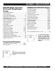
MQ-D306HA — TABLE OF CONTENTS MQ-D306HA Gasoline Powered Diaphragm Pump HONDA GX120K1QX2 Engine Air Cleaner Assembly......................................... 36-37 Camshaft Assembly ........................................... 38-39 Carburetor Assembly ......................................... 40-41 Control Assembly ............................................... 42-43 Crankcase Cover Assembly ............................... 44-45 Crankshaft Assembly .........................................
www.multiquip.com Effective: June 1st, 2005 PARTS ORDERING PROCEDURES Ordering parts has never been easier! Choose from three easy options: Best Deal! Order via Internet (Dealers Only): If you have an MQ Account, to obtain a Username and Password, E-mail us at: parts@multiquip.com. Order parts on-line using Multiquip’s SmartEquip website! ■ View Parts Diagrams ■ Order Parts ■ Print Specification Information To obtain an MQ Account, contact your District Sales Manager for more information.
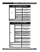
MQ-D306HA— SPECIFICATIONS (PUMP/ENGINE) Table 1. Specifications (Pump) Pump Type MQ-306H Diaphragm Pump Suction & Discharge Size 3.00 in. (76 mm.) Maximum Pumping Capacity 5,100 gallons/hour (19,305 liters/hour) Max. Soilds Diameter 1.5 in. (38 mm) Max Lift 25 ft. (7.62 meters) Max. Head 50 ft. (15.24 meters) 160 lbs. (72 Kg.) Dry Net Weight Table 2.
MQ-D306HA— DIMENSIONS (PUMP) Figure 1. MQ-D306HA Pump Dimensions Table 3. Dimensions MODEL A LENGTH B WIDTH C HEIGHT MQ-306HA 36.0 in. (91 cm.) 19.0 in. (48 cm.) 2 7 .0 in . (69 cm.) MQ-D306HA DIAPHRAGM PUMP — OPERATION AND PARTS MANUAL— REV.
MQ-D306HA— SAFETY MESSAGE ALERT SYMBOLS FOR YOUR SAFETY AND THE SAFETY OF OTHERS! HAZARD SYMBOLS Safety precautions should be followed at all times when operating this equipment. Failure to read and understand the Safety Messages and Operating Instructions could result in injury to yourself and others. This Owner's Manual has been developed to provide complete instructions for the safe and efficient operation of the MQ Model NOTE D306HA Diaphragm Pump.
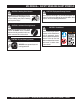
MQ-D306HA— SAFETY MESSAGE ALERT SYMBOLS CAUTION - Rotating Parts Hazards NEVER operate equipment with covers, or guards removed. Keep fingers, hands, hair and clothing away from all moving parts to prevent injury. CAUTION - Equipment Damage Hazards Other important messages are provided throughout this manual to help prevent damage to your light tower, other property, or the surrounding environment.
MQ-D306HA — RULES FOR SAFE OPERATION DANGER Read this manual! Failure to follow instructions in this manual may lead to serious injury or even death! This equipment is to be operated by trained and qualified personnel only! This equipment is for industrial use only. The following safety guidelines should always be used when operating the MQ Model D-306H Diaphragm Pump. GENERAL SAFETY ■ DO NOT operate or service this equipment before reading this entire manual.
MQ-D306HA — RULES FOR SAFE OPERATION ■ ALWAYS be sure the operator is familiar with proper safety precautions and operation techniques before using pump. ■ NEVER leave the pump unattended, turn off engine when unattended. ■ ■ ■ ■ ■ ■ ■ ■ ■ TRANSPORTING ■ ALWAYS shutdown engine before transporting. ■ Tighten fuel tank cap securely and close fuel cock to prevent fuel from spilling. NEVER pump volatile, explosive, flammable or low flash point ■ Drain fuel when transporting pump over long distances fluids.
MQ-D306HA — GENERAL INFORMATION APPLICATION The MQ Model D305HA diaphragm pump is designed to be used for de-watering applications. The suction and discharge ports on this pump use a 3-inch diameter opening, which allows the pump to pump at rate of approximately 5,100 gallons/hour (gph) or 19,305 liters/hour (lph). Elevation Higher elevations will effect the performance of the pump. Due to less atmospheric pressure at higher altitudes, pumps DO NOT have the priming ability that they have at sea level.
MQ-D306HA — PUMP COMPONENTS Figure 2 shows a typical application using the MQ D306HA series diaphragm pump. Please note that this pump is intended for the removal of clean water and water containing some debris and solids. Maximum size of solids should not exceed 1.5 inch (38 mm) in diameter. DO NOT set strainer on bottom of water bed. Placing the strainer above the water bed will prevent the pump from drawing in excessive amounts of sand and foreign debris.
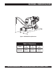
MQ-D306HA — BASIC ENGINE Figure 3. Engine Controls and Components INITIAL SERVICING The engine (Figure 3) must be checked for proper lubrication and filled with fuel prior to operation. Refer to the Honda manufacturers engine manual for instructions and details for operation and servicing. 1. 6. Choke Lever – Used in the starting of a cold engine, or in cold weather conditions. The choke enriches the fuel mixture. 7. Air Cleaner – Prevents dirt and other debris from entering the fuel system.
MQ-D306HA — PRE-INSPECTION (ENGINE) CAUTION - Read Manual Please read the entire maintenance section in this manual before servicing the pump. In addition for operator safety, please read all safey messages at the begining of the manual Inspection 1. Clean the pump, removing dirt and dust, particularly the engine cooling air inlet, carburetor and air cleaner. 2. Check the air filter for dirt and dust. If air filter is dirty, replace air filter with a new one as required. 3.
MQ-D306HA — PRE-SETUP (PUMP) 3. Remember suction hoses must be rigid enough not to collapse when the pump is in operation. Before Starting: CAUTION - General Safety Precautions NEVER operate the pump in a confined area or enclosed area structure that does not provide ample free flow of air. ALWAYS wear approved eye and hearing protection before operating the compactor. 4. Check that the discharge hose (Figure 2) is not restricted. Place hose so that it lays as straight as it is possible on the ground.
MQ-D306HA — PRE-SETUP (PUMP) Gear Reduction Oil (Transmission) 1. Remove the transmission oil level plug (Figure 6). If oil begins to seep out as the plug is being removed, then it can be assumed that the transmission oil is at the proper operating level. 2. If oil does not seep out as the oil level plug is being removed, then remove the transmission oil fill plug and fill with SAE 80/90 EP gear oil to the proper operating level. Transmission oil capacity is capacity is 1-1/4 pints (590 ml.). Figure 6.
MQ-D306HA— INITIAL START-UP (ENGINE) CAUTION - Read Manual 4. Place the choke lever (Figure 9) in the "CLOSED " position if starting a warm engine or the temperature is warm. DO NOT attempt to operate the pump until the Safety, General Information and Inspection sections of this manual have been read and thoroughly understood. This section is intended to assist the operator with the initial start-up of the diaphragm pump.
MQ-D306HA— INITIAL START-UP (ENGINE) 7. If the engine has started, slowly return the choke lever (Figure 14 ) to the “CLOSED” position. If the engine has not started repeat steps 1 through 6. Stopping The Engine Normal Shutdown 1. Move the throttle lever to the IDLE position (Figure 16) and run the engine for three minutes at low speed. Figure 16. Throttle Lever (Idle) Figure 14. Choke Lever (Closed) 2. After the engine cools, turn the engine ON/OFF switch to the “OFF” position (Figure 17). 8.
MQ-D306HA — MAINTENANCE (PUMP) Pump Vacuum Test Pump Cleaning CAUTION - Priming Pump DO NOT attempt to start the engine unless the pump has previously been primed with water. Severe pump damage will occur if pump has not been primed. To perform the pump vacuum test do the following: 1. Remove the pump fill cap (Figure 2), and fill the pump with water. 2. Start the engine as outlined in the initial start-up section, and wait for the pump to begin pumping. 3.
MQ-D306HA — MAINTENANCE (PUMP) Figure 19. Pump Vacuum Tester NOTE Pressure reading may vary depending on altitude. See Tables 3 and 4. MQ-D306HA DIAPHRAGM PUMP — OPERATION AND PARTS MANUAL— REV.
MQ-D306HA — MAINTENANCE (ENGINE) Engine Maintenance Perform engine maintenance procedures as referenced by Table 6 below: Table 6. Engine Maintenance Schedule DESCRIPTION (3) OPERATION BEFORE CHECK X FIRST EVERY MONTH 3 MONTHS OR OR 10 HRS. 25 HRS. EVERY 6 MONTHS OR 50 HRS. EVERY YEAR OR 100 HRS. EVERY 2 YEARS OR 200 HRS.
MQ-D306HA — MAINTENANCE (ENGINE) Maintenance DANGER - Combustion (Fire , Explosion) Perform the engine maintenance procedures as indicated below: DAILY ■ Thoroughly remove dirt and oil from the engine and control area. Clean or replace the air cleaner elements as necessary. Check and retighten all fasteners as necessary. Check the spring box and bellows for oil leaks. Repair or replace as needed. WEEKLY ■ Remove the fuel filter cap and clean the inside of the fuel tank.
MQ-D306HA — PREPARATION FOR LONG -TERM STORAGE Pump Storage For storage of the pump for over 30 days, the following is required: z Drain the fuel tank completely. z Run the engine until the fuel is completely consumed. z Completely drain used oil from the engine crankcase and fill with fresh clean oil, then follow the procedures described in the engine manual for engine storage. z Remove the pump cover and clean inside of pump housing.
MQ-D306HA — TROUBLESHOOTING (ENGINE) TABLE 7. ENGINE TROUBLESHOOTING SYMPTOM POSSIBLE PROBLEM SOLUTION Difficult to start Fuel is available but spark plug will not ignite. (Power available at high tension cable). Fuel is available but spark plug will not ignite. (Power NOT available at high tension cable). Fuel is available and spark plug ignites (compression normal). Fuel is available and spark plug ignites (compression low ). Ignition plug being bridge? Check ignition system.
MQ-D306HA — TROUBLESHOOTING (ENGINE/PUMP) TABLE 7. ENGINE TROUBLESHOOTING (Continued) SYMPTOM POSSIBLE PROBLEM SOLUTION Operation not satisfactory Rotational speed fluctuates. Recoil star ter not working properly. Governor adjustment improper? Adjust governor to correct lever. Governor spring defective? Clean or replace ignition. Fuel flow erratic? Check fuel line. Air taken in through suction line? Check suction line. Dust in rotating par t? Clean recoil star ter assembly.
NOTE PAGE MQ-D306HA DIAPHRAGM PUMP — OPERATION AND PARTS MANUAL— REV.
MQ-D306HA — EXPLANATION OF CODE IN REMARKS COLUMN How to read the marks and remarks used in this parts book. NOTE Items Found In the “Remarks” Column The contents of this catalog are subject to change without notice. Serial Numbers-Where indicated, this indicates a serial number range (inclusive) where a particular part is used. Model Number-Where indicated, this shows that the corresponding part is utilized only with this specific model number or model number variant.
MQ-D306HA— SUGGESTED SPARE PARTS MQ-D306HA DIAPHRAGM PUMP 1 TO 3 UNITS WITH HONDA GX120K1QX2 ENGINE Qty. P/N Description 3 ......... 17210ZE0505 .. ELEMENT AIR CLEANER DUAL 3 ......... 9807955846 ..... SPARK PLUG 1 ......... 17620ZH7023 .. CAP, FUEL WITH GASKET 1 ......... 28462ZH8003 .. ROPE STARTER 1 ......... 3052726 ........... DIAPHRAGM 2 ......... 3054937 ........... FLAP VALVE 1 ......... 1506060 ........... PLUG, FILL PLASTIC 1 ......... 1506064 ........... O-RING 1 ......... 0742304080 .....
MQ-D306HA — WATERBOX AND GROOVE ASSY. WATERBOX AND GROOVE ASSY. PAGE 30 — MQ-D306HA DIAPHRAGM PUMP — OPERATION AND PARTS MANUAL — REV.
MQ-D306HA — WATERBOX AND GROOVE ASSY. WATERBOX AND GROOVE ASSY. NO. PART NO. PART NAME 1 3053041 NIPPLE, SUCTION AND DISCHARGE 2 3054932 SUCTION CONNECTION 3 3065985 STUD 3/8”-16 X 2-1/8”, H.N., L.W.
MQ-D306HA — PUMP ASSY. PUMP ASSY. PAGE 32 — MQ-D306HA DIAPHRAGM PUMP — OPERATION AND PARTS MANUAL — REV.
MQ-D306HA — PUMP ASSY. PUMP NO. 23 24 25 26 27 28 29 30 31 32 33 34 35 36 37 38 39 40 41 42 43 44 45 46 47 48 49 50 51 52 53 54 55 56 57 58 59 60 ASSY. PART NO. 3064771 3051213 3051200 3054850 2024540 3054858 2063070 2024853 2020807 2025058 2063040 2024852 2023417 2023020 2021434 2064851 2021827 2061880 3051421 2021421 2024945 3051420 2021402 2024854 2029106 2025100 2024859 2024856 2025160 2025165 2025601 2025162 2025167 GX120K1QX2 3054953A 2024964 3051012 3053317 PART NAME QTY.
MQ-D306HA— PUMP ASSY. (CONT.) PUMP ASSY. (CONT.) PAGE 34 — MQ-D306HA DIAPHRAGM PUMP — OPERATION AND PARTS MANUAL — REV.
MQ-D306HA — PUMP ASSY. (CONT.) PUMP ASSY. (CONT.) NO. PART NO.
HONDA GX120K1QX2 ENGINE — AIR CLEANER ASSY. AIR CLEANER ASSY. PAGE 36 — MQ-D306HA DIAPHRAGM PUMP — OPERATION AND PARTS MANUAL — REV.
HONDA GX120K1QX2 ENGINE — AIR CLEANER ASSY. AIR CLEANER ASSY. NO. 1 2 3 * 4 5 * 7# 8# 9 12 13 14 PART NO. 16271ZE1000 17210ZE0505 17218ZE0505 17230ZE0820 17232891000 17238ZE0010 17239ZE1000 17410ZE0030 90325044000 957010602000 9405006000 PART NAME QTY. REMARKS GASKET, ELBOW 1 ELEMENT, AIR CLEANER (DUAL) ................... 1............. INCLUDES ITEMS W/ * FILTER, OUTER 1 COVER, AIR CLEANER (DUAL) 1 GROMMET, AIR CLEANER 1 COLLAR, AIR CLEANER 2 COLLAR B, AIR CLEANER 1 ELBOW, AIR CLEANER ..................
HONDA GX120K1QX2 ENGINE — CAMSHAFT ASSY. CAMSHAFT ASSY. PAGE 38 — MQ-D306HA DIAPHRAGM PUMP — OPERATION AND PARTS MANUAL — REV.
HONDA GX120K1QX2 ENGINE — CAMSHAFT ASSY. CAMSHAFT ASSY. NO. 1 2 3 4 5 6 * 7 8 9 10 11 12 13 14 15 PART NO. 14100ZE0812 14410ZE0010 14431ZE1000 14441ZE1010 14451ZE1013 14568ZE1000 14711ZF0010 14721ZF0000 14751ZF1000 14771ZE1000 14773ZE1000 14781ZE1000 14791ZE0010 90012ZE0010 90206ZE1000 PART NAME QTY. REMARKS CAMSHAFT ASSEMBLY .................................. 1............. INCLUDES ITEMS W/ * ROD, PUSH 2 ARM, VALVE ROCKER 2 LIFTER, VALVE 2 PIVOT, ROCKER ARM 2 SPRING, WEIGHT RETURN 1 VALVE, IN.
HONDA GX120K1QX2 ENGINE — CARBURETOR ASSY. CARBURETOR ASSY. PAGE 40 — MQ-D306HA DIAPHRAGM PUMP — OPERATION AND PARTS MANUAL — REV.
HONDA GX120K1QX2 ENGINE — CARBURETOR ASSY. CARBURETOR ASSY. NO. 1 * 2 * 3 * 4 * 5 * 6 * 7 * 8 * 9 10 * 11 * 12 * 13 14 15 16 17 18 * 19 * 20 * 21 * 22 * 23 * 24# 25 25 25 * 26 * PART NO.
HONDA GX120K1QX2 ENGINE — CONTROL ASSY. CONTROL ASSY. PAGE 42 — MQ-D306HA DIAPHRAGM PUMP — OPERATION AND PARTS MANUAL — REV.
HONDA GX120K1QX2 ENGINE — CONTROL ASSY. CONTROL ASSY. NO. 3 4 5 6 7 8# 9# 10# 11# 12# 14# 15# 16# 18 19 20 21# 24# 25# 26 PART NO. 16500ZH7820 16551ZE0010 16555ZE0000 16561ZE0020 16562ZE0020 16571ZH7000 16574ZE1000 16575ZH8000 16576891000 16578ZE1000 16580ZH7810 16584883300 16592ZE1810 90013883000 90015ZE5010 90022888010 90114SA0000 93500050250H 93500050160A 9405006000 PART NAME QTY. REMARKS CONTROL ASSEMBLY (REMOTE) ........... 1 ............
HONDA GX120K1QX2 ENGINE — CRANKCASE COVER ASSY. CRANKCASE COVER ASSY. PAGE 44 — MQ-D306HA DIAPHRAGM PUMP — OPERATION AND PARTS MANUAL — REV.
HONDA GX120K1QX2 ENGINE — CRANKCASE COVER ASSY. CRANKCASE COVER ASSY. NO. 1 2 3 4 7# 8+ 9 10 * 11 * 12 PART NO. 11300ZE0640 11381ZH7800 15600ZE1003 15600ZG4003 15625ZE1003 15625ZE1003 90015883000 91001878003 91203ZE0003 9430108140 PART NAME QTY. REMARKS COVER ASSEMBLY, CRANKCASE (W- TYPE) ....... 1 .............. INCLUDES ITEMS W/ * GASKET, CASE COVER 1 CAP ASSEMBLY, OIL FILLER ................................ 1 .............. INCLUDES ITEMS W/# CAP ASSEMBLY, OIL FILLER ................................
HONDA GX120K1QX2 ENGINE — CRANKSHAFT ASSY. CRANKSHAFT ASSY. PAGE 46 — MQ-D306HA DIAPHRAGM PUMP — OPERATION AND PARTS MANUAL — REV.
HONDA GX120K1QX2 ENGINE — CRANKSHAFT ASSY. CRANKSHAFT ASSY. NO. 1 2 PART NO. 13310ZE0601 90745ZE1600 PART NAME CRANKSHAFT, H-TYPE KEY 4.78 X4.78X38 QTY. 1 1 REMARKS MQ-D306HA DIAPHRAGM PUMP — OPERATION AND PARTS MANUAL— REV.
HONDA GX120K1QX2 ENGINE — CYLINDER BARREL ASSY. CYLINDER BARREL ASSY. PAGE 48 — MQ-D306HA DIAPHRAGM PUMP — OPERATION AND PARTS MANUAL — REV.
HONDA GX120K1QX2 ENGINE — CYLINDER BARREL ASSY. CYLINDER BARREL ASSY. NO. 2 3 4 5# 6# 7# 8 9 10 11 12 13 14 * 15 * 16 17 18 19 20 PART NO. 120A0ZH7810 15510ZE1033 16510ZE1000 16511ZE1000 16512ZE1000 16513ZE1000 16531ZE1000 16541ZE1000 90131ZE1000 90451ZE1000 90601ZE1000 90602ZE1000 91001878003 91202ZE6003 91353671003 9405010000 9410106800 9425108000 957010601200 PART NAME QTY. REMARKS CYLINDER ASSEMBLY (OIL ALERT) ........1 ............ INCLUDES ITEMS W/ * SWITCH ASSEMBLY, OIL LEVEL 1 GOVERNOR ASSEMBLLY .
HONDA GX120K1QX2 ENGINE — CYLINDER HEAD ASSY. CYLINDER HEAD ASSY. PAGE 50 — MQ-D306HA DIAPHRAGM PUMP — OPERATION AND PARTS MANUAL — REV.
HONDA GX120K1QX2 ENGINE — CYLINDER HEAD ASSY. CYLINDER HEAD ASSY. NO. 1 2 * 3 * 4 + * 5 6 6 7 8 9 10 11 12 14 15 PART NO. 12210ZH7000 12204ZE1306 12205ZE1315 12216ZE5300 12251ZH7800 12310ZE1000 12310ZE1010 12391ZE1000 15721ZH8000 90013883000 90043ZE1020 90047ZE1000 9430110160 957230805500 9807955846 PART NAME QTY. REMARKS CYLINDER HEAD .................................................. 1 .............. INCLUDES ITEMS W/ * GUIDE, VALVE (OS) OPTIONAL 1 GUIDE, EX. VALVE (OS) OPTIONAL ................... 1 ..
HONDA GX120K1QX2 ENGINE — FAN COVER ASSY. FAN COVER ASSY. PAGE 52 — MQ-D306HA DIAPHRAGM PUMP — OPERATION AND PARTS MANUAL — REV.
HONDA GX120K1QX2 ENGINE — FAN COVER ASSY. FAN COVER ASSY. NO. 1 2 3 4 5 6 7 7 8 9 10 11 13 PART NO.
HONDA GX120K1QX2 ENGINE — FLYWHEEL ASSY. FLYWHEEL ASSY. PAGE 54 — MQ-D306HA DIAPHRAGM PUMP — OPERATION AND PARTS MANUAL — REV.
HONDA GX120K1QX2 ENGINE — FLYWHEEL ASSY. FLYWHEEL ASSY. NO. 1 2 4 5 7 PART NO. 13331357000 19511ZE0000 28451ZH8003 31100ZE0010 90201878003 PART NAME KEY, SPECIAL WOODRUFF 25X18 FAN, COOLING PULLEY, STARTER FLYWHEEL NUT, SPECIAL 14MM QTY. 1 1 1 1 1 REMARKS MQ-D306HA DIAPHRAGM PUMP — OPERATION AND PARTS MANUAL— REV.
HONDA GX120K1QX2 ENGINE — FUEL TANK ASSY. FUEL TANK ASSY. PAGE 56 — MQ-D306HA DIAPHRAGM PUMP — OPERATION AND PARTS MANUAL — REV.
HONDA GX120K1QX2 ENGINE — FUEL TANK ASSY. FUEL TANK ASSY. NO. 1 2 3 5 6 * 11 12 13 14 15 PART NO. 16854ZH8000 16955ZE1000 17510ZE0020ZD 17620ZH7023 17631ZH7003 91353671003 9405006000 950014500360M 9500202080 90004ZH7003 PART NAME QTY. REMARKS RUBBER, SUPPORTER 107MM 1 JOINT, FUEL TANK 1 TANK, FUEL *NH1* (BLACK) 1 CAP, FUEL FILLER ..................................... 1 .......... INCLUDES ITEMS W/ * GASKET, FUEL FILLER CAP 1 O- RING 13.5X1.5 (ARAI) 1 NUT, FLANGE 6MM 2 BULK HOSE, FUEL (4.5X3000) (4.
HONDA GX120K1QX2 ENGINE — IGNITION COIL ASSY. IGNITION COIL ASSY. PAGE 58 — MQ-D306HA DIAPHRAGM PUMP — OPERATION AND PARTS MANUAL — REV.
HONDA GX120K1QX2 ENGINE — IGNITION COIL ASSY. IGNITION COIL ASSY. NO. 1 2 8 PART NO. 30500ZE1033 30700ZE1013 90121952000 PART NAME COIL ASSEMBLY, IGNITION CAP ASSEMBLY, NOISE SUPPRESSOR BOLT, FLANGE 6X25 QTY. 1 1 2 REMARKS MQ-D306HA DIAPHRAGM PUMP — OPERATION AND PARTS MANUAL— REV.
HONDA GX120K1QX2 ENGINE — MUFFLER ASSY. MUFFLER ASSY. PAGE 60 — MQ-D306HA DIAPHRAGM PUMP — OPERATION AND PARTS MANUAL — REV.
HONDA GX120K1QX2 ENGINE — MUFFLER ASSY. MUFFLER ASSY. NO. 1 3 7 10 13 PART NO. 18310ZF1000 18320ZF1H01 18381ZH8800 90050ZE1000 94001080000S PART NAME MUFFLER PROTECTOR, MUFFLER GASKET, MUFFLER SCREW, TAPPING 5X8 NUT, HEX. 8MM QTY. 1 1 1 4 2 REMARKS MQ-D306HA DIAPHRAGM PUMP — OPERATION AND PARTS MANUAL— REV.
HONDA GX120K1QX2 ENGINE — PISTON ASSY. PISTON ASSY. PAGE 62 — MQ-D306HA DIAPHRAGM PUMP — OPERATION AND PARTS MANUAL — REV.
HONDA GX120K1QX2 ENGINE — PISTON ASSY. PISTON ASSY. NO. 1 1 1 1 2 2 2 2 3 4 4 5 * 6 PART NO. 13010ZK7V01 13011ZE6013 13012ZK7V01 13013ZK7V01 13101ZH7000 13102ZH7000 13103ZH7000 13104ZH7000 13111ZE0000 132A0ZE0000 13200ZE0000 90001ZE1000 90551ZE0000 PART NAME QTY. REMARKS RING SET, PISTON (STANDARD) 1 RING SET, PISTON (OS 0.25), OPTIONAL 1 RING SET, PISTON (OS 0.50) , OPTIONAL 1 RING SET, PISTON (OS 0.75), OPTIONAL 1 PISTON, STANDARD 1 PISTON, OS 0.25 1 PISTON, OS 0.50 1 PISTON, 0.
HONDA GX120K1QX2 ENGINE — RECOIL STARTER ASSY. RECOIL STARTER ASSY. PAGE 64 — MQ-D306HA DIAPHRAGM PUMP — OPERATION AND PARTS MANUAL — REV.
HONDA GX120K1QX2 ENGINE — RECOIL STARTER ASSY. RECOIL STARTER ASSY. NO. 1 2 * 3 * 4 * 5 * 6 * 7 * 8 * 9 * 10 * 11 * 12 PART NO. 28400ZH8013ZB 28410ZH8003ZB 28420ZH8013 28422ZH8013 28433ZH8003 28441ZH8003 28442ZH8003 28443ZH8003 28461ZH8003 28462ZH8003 90003ZH8003 9008ZE2003 PART NAME QTY. REMARKS STARTER ASSY., RECOIL *NH1* (BLACK) .......... 1 ..............
HONDA GX120K1QX2 ENGINE — GASKET KIT ASSY. NO ARTWORK AVALIBLE PAGE 66 — MQ-D306HA DIAPHRAGM PUMP — OPERATION AND PARTS MANUAL — REV.
HONDA GX120K1QX2 ENGINE — GASKET KIT ASSY. GASKET KIT ASSY. NO. 2 3 * 4 * 5 * 6 * 7 * 8 * PART NO. 06111ZH7405 11381ZH7800 12251ZH7800 12391ZE1000 16212ZH7800 16221ZH8801 18381ZH8800 PART NAME QTY. REMARKS GASKET KIT ......................................................... 1 .............. INCLUDES ITEMS W/ * GASKET, CASE COVER 1 GASKET, CYLINDER HEAD 1 GASKET, CYLINDER HEAD COVER 1 GASKET, INSULATOR 1 GASKET, CARBURETOR 1 GASKET, MUFFLER 1 MQ-D306HA DIAPHRAGM PUMP — OPERATION AND PARTS MANUAL— REV.
Effective: February 22, 2006 PAYMENT TERMS TERMS AND CONDITIONS OF SALE — PARTS 5. Parts must be in new and resalable condition, in the original Multiquip package (if any), and with Multiquip part numbers clearly marked. 6. The following items are not returnable: Terms of payment for parts are net 30 days. FREIGHT POLICY All parts orders will be shipped collect or prepaid with the charges added to the invoice. All shipments are F.O.B. point of origin.
NOTE PAGE MQ-D306HA DIAPHRAGM PUMP — OPERATION AND PARTS MANUAL— REV.
OPERATION AND PARTS MANUAL HERE'S HOW TO GET HELP PLEASE HAVE THE MODEL AND SERIAL NUMBER ON-HAND WHEN CALLING UNITED STATES Multiquip Corporate Office 18910 Wilmington Ave. Tel. (800) 421-1244 Carson, CA 90746 Fax (800) 537-3927 Contact: mq@multiquip.com Mayco Parts 800-306-2926 Fax: 800-672-7877 310-537-3700 Fax: 310-637-3284 Service Department 800-421-1244 Fax: 310-537-4259 310-537-3700 MQ Parts Department 800-427-1244 310-537-3700 MEXICO UNITED KINGDOM MQ Cipsa Carr. Fed. Mexico-Puebla KM 126.