OPERATION AND PARTS MANUAL SERIES MODEL MRH800DS2 VIBRATORY ROLLER (YANMAR L100V1AJ1R1AAMK DIESEL ENGINE) Revision #1 (4/12/11) To find the latest revision of this publication, visit our website at: www.multiquip.com THIS MANUAL MUST ACCOMPANY THE EQUIPMENT AT ALL TIMES.
PROPOSITION 65 WARNING Diesel engine exhaust and some of PAGE 2 — MRH800DS2 VIBRATORY ROLLER • OPERATION AND PARTS MANUAL — REV.
NOTES MRH800DS2 VIBRATORY ROLLER • OPERATION AND PARTS MANUAL — REV.
TABLE OF CONTENTS MRH800DS2 Vibratory Roller Yanmar L100V1AJ1R1AAMK Engine Proposition 65 Warning ........................................... 2 Parts Ordering Procedures ...................................... 5 Safety Information .............................................. 6-10 Specifications ................................................... 12-13 Dimensions ............................................................ 14 General Information ...............................................
www.multiquip.com PARTS ORDERING PROCEDURES Ordering parts has never been easier! Choose from three easy options: Order via Internet (Dealers Only): Best Deal! Effective: January 1st, 2006 If you have an MQ Account, to obtain a Username and Password, E-mail us at: parts@multiquip. com. Order parts on-line using Multiquip’s SmartEquip website! ■ View Parts Diagrams ■ Order Parts ■ Print Specification Information To obtain an MQ Account, contact your District Sales Manager for more information.
SAFETY INFORMATION Do not operate or service the equipment before reading the entire manual. Safety precautions should be followed at all times when operating this equipment. Failure to read and understand the safety messages and operating instructions could result in injury to yourself and others. SAFETY MESSAGES The four safety messages shown below will inform you about potential hazards that could injure you or others.
SAFETY INFORMATION GENERAL SAFETY CAUTION NEVER operate this equipment without proper protective clothing, shatterproof glasses, respiratory protection, hearing protection, steel-toed boots and other protective devices required by the job or city and state regulations. NEVER operate this equipment when not feeling well due to fatigue, illness or when under medication. NEVER operate this equipment under the influence of drugs or alcohol.
SAFETY INFORMATION ROLLER SAFETY DANGER NEVER operate the equipment in an explosive atmosphere or near combustible materials. An explosion or fire could result causing severe bodily harm or even death. WARNING NEVER disconnect any emergency or safety devices. These devices are intended for operator safety. Disconnection of these devices can cause severe injury, bodily harm or even death. Disconnection of any of these devices will void all warranties.
SAFETY INFORMATION or hot. NOTICE NEVER run engine without an air filter or with a dirty air filter. Severe engine damage may occur. Service air filter frequently to prevent engine malfunction. DO NOT overfill tank, since spilled fuel could ignite if it comes into contact with hot engine parts or sparks from the ignition system. NEVER tamper with the factory settings of the engine or engine governor.
SAFETY INFORMATION rinse skin or clothing immediately with plenty of water. If the battery liquid (dilute sulfuric acid) comes into contact with eyes, rinse eyes immediately with plenty of water and contact the nearest doctor or hospital to seek medical attention. CAUTION ALWAYS disconnect the NEGATIVE battery terminal before performing service on the equipment. ALWAYS keep battery cables in good working condition. Repair or replace all worn cables. TRANSPORTING SAFETY transporting on a trailer.
NOTES MRH800DS2 VIBRATORY ROLLER • OPERATION AND PARTS MANUAL — REV.
SPECIFICATIONS Table 1. Specifications (Vibratory Roller) 105 x 27.2 x 41.7 in Dimensions (2670 x 692 x 1060 mm) Drum Diameter 16 in. (406 mm) Drum Width 25.6 in. (650 mm) Curb Clearance 9.6 in. (243 mm) Side Overhang .83 in.(21 mm) Operating Weight (with water) 1562 lbs. (710 kg) Vibration Frequency 3,300 vpm Centrifugal Force 23.5/2,400 kn/kgf Drive System Hydraulic Motor Vibration System Frame Vibration Method Belt Drive Vibrator Shaft Twin Gradeablility 35 degrees Working Speed 0 - 3 mph (0 - 4.
SPECIFICATIONS Engine Model Engine Type Cylinder Bore X Stroke Displacement Maximum Ouput Fuel Tank Capacity Oil Capacity Dry Net Weight Dimensions (L x W x H) Table 2. Specifications (Engine) YANMAR L100V1AJ1R1AAMK Air-cooled Diesel 3.4 x 2.95 in (86 x 75 mm) 14.7 fl oz (435 cc) 8.7 HP 5.6 quarts (5.4 liters) 1.7 quarts (1.6 liters) 117.9 lbs. (54 kg) 16.22 x 18.54 x 19.45 in (412 x 471 x 494 mm) MRH800DS2 VIBRATORY ROLLER • OPERATION AND PARTS MANUAL — REV.
DIMENSIONS Figure 1. MRH800DS2 Dimensions LENGTH WIDTH HEIGHT Table 3. Dimensions A 105 in. B 57 in. C 10 in. D 22.8 in. E 13.8 in. F 27.2 in. G 13.6 in. H 78.3 in. I 46.5 in. J 37.4 in. K 41.7 in. L 9.6 in. 2670 mm. 1445 mm. 255 mm. 580 mm. 350 mm. 692 mm. 346 mm. 1990 mm. 1180 mm. 950 mm. 1060 mm. 245 mm. PAGE 14 — MRH800DS2 VIBRATORY ROLLER • OPERATION AND PARTS MANUAL — REV.
GENERAL INFORMATION The Mikasa Model MRH800DS2 is a powerful compacting tool capable of applying tremendous force in consecutive impacts to a soil surface. Its applications include soil compacting for backfilling for gas pipelines, water pipelines and cable installation work. The impact force of the MRH800DS2 levels and uniformly compacts voids between soil particles to increase dry density. Features include: Hydraulic transmission to allow speed change without gear shifting.
COMPONENTS 1 2 4 3 8 9 5 6 10 11 7 Figure 2. MRH800DS2 Components PAGE 16 — MRH800DS2 VIBRATORY ROLLER • OPERATION AND PARTS MANUAL — REV.
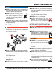
COMPONENTS Figure 2 illustrates the location of the major components for the MRH800DS2 Vibration Roller. The function of each component is described below: 1. Fuel Tank/Cap — Fill with diesel fuel. Fuel tank holds approximately 2 gallons (7.5 liters). DO NOT top off fuel. Wipe up any spilled fuel immediately. 2. Center Cover — When opened and supported by strut, provides access to oil pump and filter, battery, V-belt, and clutch box. 3.
COMPONENTS 1 3 2 4 6 5 Figure 3. Handle Bar/Lever Components PAGE 18 — MRH800DS2 VIBRATORY ROLLER • OPERATION AND PARTS MANUAL — REV.
COMPONENTS HANDLE BAR/LEVER COMPONENTS Figure 3 illustrates the location of the major lever components on the handle bar of the machine. Each component is described below: 1. Travel Lever — Controls the direction of travel of the machine (forward and reverse). 2. Horn Button — When pressed, gives a warning sound of the machine approaching. 3. Vibration Lever — Turns vibration on and off. 4. Throttle Lever — Controls the start up of the machine. 5.
BASIC ENGINE Figure 4. Yanmar Engine Components ENGINE COMPONENTS Figure 4 illustrates the location of the major engine components. Each component is described below: 1. Fuel Filler Cap — Remove this cap to add unleaded gasoline to the fuel tank. Make sure cap is tightened securely. DO NOT over fill. 2. Fuel Tank — Diesel engine holds 5.7 quarts of diesel fuel. 3. Air Cleaner — Prevents dirt and other debris from entering the fuel system.
NOTES MRH800DS2 VIBRATORY ROLLER • OPERATION AND PARTS MANUAL — REV.
INSPECTION BEFORE STARTING CHECKING THE HYDRAULIC SYSTEM 1. Read safety information at the beginning of manual. 1. Check the oil tank level gauge (Figure 6). Oil level should be at the middle indication of the gauge or higher. Fill as required. 2. Remove dirt and dust, particularly in the engine cooling air inlet, carburetor and air cleaner. 3. Check the air filter for dirt and dust. If air filter is dirty, replace air filter with a new one. 4. Check carburetor for external dirt and dust.
INSPECTION CHECKING THE VIBRATOR OIL LEVEL CHECKING LEVERS AND HORN 1. Check vibrator casing for any oil leakage. 1. Check travel, vibration, and throttle levers to make sure they are functioning properly (Figure 3). 2. If any leakage is noticed, remove the level plug on the side of the plate (Figure 8). 2. With travel lever placed in reverse, push the deadman device and verify that the travel lever returns to neutral position.
OPERATION CAUTION DO NOT attempt to operate the roller until the Safety Information, General Information, and Inspection sections of this manual have been read and thoroughly understood. 4. Turn the starter key further to the right to the START position (Figure 14) to start the engine. Buzzer stops sounding when the engine speed increases. With safety switch equipped, motor runs only when the travel lever is in the neutral position.
OPERATION 4. Push down the decompression lever (Figure 16). 6. Push the travel lever backward to go in the reverse direction. CAUTION Do not reduce speed during work. When shifting travel lever from forward to reverse, be sure to stop the lever at the neutral position first before moving the lever to the opposite direction. Do not shift the lever from forward to reverse (or reverse to forward) in one motion. Figure 16. Decompression lever 5.
OPERATION WATERING UNLOADING 2. For watering work, turn the water cocks clockwise, at the rear of the machine, to start sprinkling. (Figure 19). 5. If you need to move the roller by pushing it manually once engine is stopped, loosen bolt of bypass valve on oil pump by one rotation counterclockwise. This will cause the hydraulic brake to disengage and allow the roller to be moved more easily (Figure 20). WATER COCK FOR FRONT DRUM WATER COCK FOR REAR DRUM Bypass Valve Bolt Figure 19.
OPERATION TRANSPORTING 1. Always make sure that the machine is shut off while being transported. 2. Check that the fuel cap is properly closed and tightened. 3. When traveling long distances or on rugged terrain, drain the fuel of the machine before transporting. 4. Tie down the machine securely on the transportation so that it will not move or topple over. CAUTION Inspection and other services should always be carried out on hard and level ground with the engine shutdown.
MAINTENANCE CAUTION Inspection and other services should always be carried out on hard and level ground with the engine shutdown. INSPECTION AND MAINTENANCE SERVICE TABLES To make sure your vibratory roller is always in good working condition before using, carry out the maintenance inspection procedures. Table 5.
MAINTENANCE AIR FILTER 1. The air filter element should be cleaned because a clogged air cleaner can cause poor engine starting, lack of power and shorten engine life substantially. 2. To clean or replace air filter loosen the wing nut on the air filter housing (Figure 21) remove the cover and take out air filter cartridge. If only cleaning of the air filter is desired blow through the air filter cartridge from the inside, moving a jet of dry compressed air up and down until all dust is removed.
MAINTENANCE MACHINE MAINTENANCE 1. At the end of each day’s operation, wash down dust and dirt off the machine. Clean area around drums ad scrapers making sure all mud is removed. 2. Drain water tank completely. 3. Cover the machine to prevent dust and store in dry place away from sun exposure. LONG TERM STORAGE 1. Conduct thorough lubrication and oil change. 2. Disconnect battery terminals and dismount battery from machine. Store battery. • completely charged: 1.270 - 1.290 • needs charging: 1.
MAINTENANCE Table 8. Lubrication Chart ITEM MAINTENANCE NEEDED FREQUENCY TYPE LOCATION Vibrator Oil Replace Oil Every 300 Hours of Operation SAE10W30 (1.
MAINTENANCE VIBRATOR OIL LEVEL PLUG HANDLE BAR RELEASE PIN GREASE FITTING VIBRATOR OIL DRAIN PLUG Figure 27. Handle Bar Maintenance Figure 25. Vibrator Oil Maintenance BEARING COVER GREASE FITTING BEARING COVER GREASE FITTING CLUTCH BOX GREASE FITTING Figure 28. Clutch Box Maintenance HYDRAULIC OIL FILTER Figure 29. Hydraulic Oil Filter Location Figure 26. Bearing Cover Maintenance PAGE 32 — MRH800DS2 VIBRATORY ROLLER • OPERATION AND PARTS MANUAL — REV.
TROUBLESHOOTING SYMPTOM Unit does not travel. Unit does not travel or travel is not smooth. Unit does not vibrate or has weak vibration. Troubleshooting - Roller POSSIBLE PROBLEM SOLUTION Parking brake still engaged? Release parking brake lever. Defective centrifugal clutch? Repair or replace clutch. Damaged rubber coupling and flange? Defective travel cable and link? Damaged scraper or too much mud in scraper? Damaged or clogged oil filter? Replace rubber coupling and flange.
TROUBLESHOOTING Troubleshooting (Engine) Symptom Engine will not start or start is delayed, although engine can be turned over. At low temperatures engine will not start. Engine fires but stops soon as starter is switched off. Engine stops by itself during normal operation. Low engine power, output and speed. Possible Problem Solution No Fuel reaching injection pump? Add fuel. Check entire fuel system. Defective fuel pump? Replace fuel pump.
TROUBLESHOOTING Troubleshooting (Engine) - continued Symptom Low engine power output and low speed, black exhaust smoke. Engine overheats. Possible Problem Solution Air filter blocked? Clean or replace air filter. Incorrect valve clearances? Adjust valves per engine specification. Malfunction at injector? See engine manual. Too much oil in engine crankcase? Drain off engine oil down to uppermark on dipstick.
EXPLANATION OF CODE IN REMARKS COLUMN The following section explains the different symbols and remarks used in the Parts section of this manual. Use the help numbers found on the back page of the manual if there are any questions. NOTICE The contents and part numbers listed in the parts section are subject to change without notice. Multiquip does not guarantee the availability of the parts listed. SAMPLE PARTS LIST NO. 1 2% 2% 3 4 PART NO. PART NAME QTY. REMARKS 12345 BOLT .....................1 .....
SUGGESTED SPARE PARTS MRH800DS2 VIBRATORY ROLLER WITH YANMAR L100V1AJ1R1AAMK DIESEL ENGINE 1 to 3 units Qty. P/N Description 1............954407840............FILTER, WATER TANK 2............954001380............FILTER, HYDRAULIC OIL 2............070503000............V-BELT, ENGINE 1............956100022............THROTTLE WIRE 1............954300342............CAP, WATER TANK 2............070100381............V-BELT, VIBRATOR ASSY. 1............71421053100........VALVE ASSY., FUEL INJECTOR 1............
NAMEPLATES AND DECALS 28 13 16 CARSON, CALIF. MRH800DS 14 35 3 23 8 4 NPA-333 J 12 18 L J TO OPERATE WITHOUT VIBRATION KEEP THE LEVER AT OFF POSITION. G 17 22 CAUTION NPA-249 E CAUTION READ OWNER’S MANUAL NPA-629 6 WARNING Should the machine be necessary to be parked on an incline, place travel lever in stop position first and block front and rear drums. Then stop the engine.
NAMEPLATES AND DECALS NO. 1 2 3 4 5 6 7 8 9 10 11 12 13 14 15 16 17 18 19 20 21 22 23 24 25 26 27 28 29 30 31 32 33 34 35 PART NO. 920205690 920209660 920206280 920102490 920101480 DCL210 920108070 920100120 920208070 920206160 920206200 920203330 920201910 920101510 920200320 920207620 920206290 920202810 920104280 920213000 920207870 920205640 920105170 920207860 920201450 920202920 920207880 920106760 920106790 920106780 515010080 920205080 920214100 920206080 920202910 PART NAME QTY.
AXLE ASSY. 32 45 38 16 39 33 REAR 38 19 39 45 31 32 35 34 36 B 45 34 38 16 39 40 36 37 32B 40 A 45 D 39 16 15 38 16 35 36 39 33 30 41 36 C 32B 37 27 SEE ITEM 31, HYDRAULIC SYSTEM ASSY. 25 B 42 28 29 FRONT 26 20 44 43 2 3 8 18 4 17 D 16 A 23 14 7 17 16 15 15 10 9 13 11 12 5 6 22 7 10 12 11 24 19 21 C 1 PAGE 40 — MRH800DS2 VIBRATORY ROLLER • OPERATION AND PARTS MANUAL — REV.
AXLE ASSY. NO. 1 2 3 4 5 6 7 8 9 10 11 12 13 14 15 16 17 18 19 20 21 22 23 24 25 26 27 28 29 30 31 32 33 34 35 36 37 38 39 40 41 42 43 44 45 PART NO.
BASE ASSY. PAGE 42 — MRH800DS2 VIBRATORY ROLLER • OPERATION AND PARTS MANUAL — REV.
BASE ASSY. NO. 1 2 3 4 5 6 7 8 10 11 12 13 14 15 16 17 18 30 32 33 34 35 36 56 57 58 59 60 61 63 64 66 67 68A* 68-1+ 68-2+ 69 72 73 91 92 93 94 95 96 PART NO.
FRONT GUARD ASSY. PAGE 44 — MRH800DS2 VIBRATORY ROLLER • OPERATION AND PARTS MANUAL — REV.
FRONT GUARD ASSY. NO. 75 76 77 78 79 80 81 82 84 PART NO. 031110160 030210250 001221035 515336200 515336210 515449720 001221040 031110160 953405940 PART NAME FLAT WASHER, M10 LOCK WASHER, M10 BOLT 10X35 MM FRONT GUARD BUMPER SPACER, BUMPER BOLT 10X40 T WASHER, FLAT M10 PIPE INSERT PZ-7 QTY. 2 2 2 1 2 4 4 4 2 REMARKS MRH800DS2 VIBRATORY ROLLER • OPERATION AND PARTS MANUAL — REV.
SIDE COVER ASSY. PAGE 46 — MRH800DS2 VIBRATORY ROLLER • OPERATION AND PARTS MANUAL — REV.
SIDE COVER ASSY. NO. 3 20 21 24 25 26 27 29 31 32 33 34 35 36 38 39 40 97 98 99 170 171 172 173 174 175 176 177 178 179 PART NO. 030210250 515336250 515449890 515334600 515010090 515010100 092004008 515113080 515447030 012210020 031110160 0105050616 030206150 952404470 0105091025 515447380 025910060 091004016 031104080 020304030 515910100 515214241 515450780 515450790 091004015 031104080 030204100 001220815 031108160 030208200 PART NAME QTY.
WATER TANK ASSY. PAGE 48 — MRH800DS2 VIBRATORY ROLLER • OPERATION AND PARTS MANUAL — REV.
WATER TANK ASSY. NO. 41 42 43 44 45 46 47 48 49 50 51 52 53 54 55 62 65 70 71 74 75 76 86 87 PART NO. 515119400 954300342 001241030 033910010 022910180 954404910 954404840 953404900 959404880 506403990 953404000 506434680 506434690 001221253 030212300 954405680 516454950 515449870 517338540 001220610 031106100 030206150 515449880 952405950 PART NAME WATER TANK CAP, WATER TANK /MR BOLT 10X30 U WASHER 10.
HYDRAULIC SYSTEM ASSY. PAGE 50 — MRH800DS2 VIBRATORY ROLLER • OPERATION AND PARTS MANUAL — REV.
HYDRAULIC SYSTEM ASSY. NO. 7 7-1* 7-2* 8 9 10 11 12 14 14 15 16 17 18 19 20 21 22 23 24 25 26 27 27 28 29 29 30 31 32 33 34 35 36 37 38 39 40 41 PART NO.
HYDRAULIC SYSTEM ASSY. PAGE 52 — MRH800DS2 VIBRATORY ROLLER • OPERATION AND PARTS MANUAL — REV.
HYDRAULIC SYSTEM ASSY. CONTINUED NO. PART NO. 42 515447160 43 515447170 44 001520820 45 515447140 46 012221020 47 031110160 48 954002630 53 507010110 55 014208020 56 030208200 57 954001520 59 515335300 60 954001090 61 954002660 62 954001620 64 954090004 65 954090005 66 954001100 67 454010020 68 959021810 69 959021810 70 954001040 81 515335451 82 0109051045 83 012010030 84 954405550 PART NAME QTY.
HYDRAULIC OIL TANK ASSY. PAGE 54 — MRH800DS2 VIBRATORY ROLLER • OPERATION AND PARTS MANUAL — REV.
HYDRAULIC OIL TANK ASSY. NO. 1 2 3 4 5 13 18 34 47 54 PART NO. 515118050 953405840 953402930 953400270 953405260 955407500 030210250 012210035 031110160 0105091025 PART NAME QTY. REMARKS OIL TANK , (N) 1 DRAIN PLUG M18 1 COPPER PACKING 19X30X1 1 PLUG 1/4X14 10L 1 PACKING 1/4 (CU) 1 OIL GAUGE/KLA-60-A-B 1 WASHER, LOCK M10 22 BOLT 10X35 T...................................................14...............REPLACES 001221035 WASHER, FLAT M10 IN SYSTEM 8 BOLT 10X25 T............................................
ENGINE ASSY. PAGE 56 — MRH800DS2 VIBRATORY ROLLER • OPERATION AND PARTS MANUAL — REV.
ENGINE ASSY. NO. PART NO. PART NAME QTY.
ELECTRIC DEVICE ASSY. 28 3738 33 70 35 34 SWITCH(CA104) 27 36 31 32 48 47 46 STARTER(CB104) 1-A 1 49 15 16 3 13 80 16 16 2 17 11 12 17 9 8 54 55 17 7 14 10 4 17 16 5 18 6 53 52 PAGE 58 — MRH800DS2 VIBRATORY ROLLER • OPERATION AND PARTS MANUAL — REV.
ELECTRIC DEVICE ASSY. NO. 1 1A* 2 3 4 5 6 7 8 9 10 11 12 13 14 15 16 17 18 27 28 31 32 33 34 35 36 37 38 46 47 48 49 52 53 54 55 70 80 PART NO.
CLUTCH (VIBRATION) ASSY. PAGE 60 — MRH800DS2 VIBRATORY ROLLER • OPERATION AND PARTS MANUAL — REV.
CLUTCH (VIBRATION) ASSY. NO. A 1* 2* 3* 4* 5* 6* 7* 8* 9* 10* 11* 12* 13* 14 * 15* 16* 17* 18* 19* 20* 21* 22* 23* 24* 25* 26* 27* 28* 29* 30* 31* PART NO. 515910010 515447070 515212980 951403020 043006206 080100620 952402470 012010030 030210250 509434770 509434780 044006008 080100680 080200400 515447080 515447090 515447100 044006305 012210020 509324690 509434850 509434860 952401690 010505506 030206150 509434870 509434880 515334200 515334210 509434840 012010030 505015060 PART NAME QTY.
VIBRATOR ASSY. PAGE 62 — MRH800DS2 VIBRATORY ROLLER • OPERATION AND PARTS MANUAL — REV.
VIBRATOR ASSY. NO. 1 2 3 6 7 8 8-1 9 10 11 12 13 14 15 16 17 18 19 20 21 22 23 24 25 27 PART NO. 515113090 515334111 515334121 040406308 501011020 501011001 501011002 951400080 952400900 001221225 030212300 953405570 060206020 080100900 515447040 951400090 952401590 070100381 515334140 515334150 014208020 030208200 894230 001221425 031108160 PART NAME QTY. REMARKS VIBRATING CASE 1 ROTARY SHAFT, DRIVE 1 ROTARY SHAFT, DRIVEN 1 BEARING 6308C4 4 GEAR SPACER 2 GEAR 38-2P 1 GEAR 38-1P 1 KEY 10X8X17 ............
UPPER CONTROL ARM ASSY. PAGE 64 — MRH800DS2 VIBRATORY ROLLER • OPERATION AND PARTS MANUAL — REV.
UPPER CONTROL ARM ASSY. NO. 8 9 10 11 12 13 14 15 16 17 18 19 20 21 22 38 40 41 42 43 44 45 46 47 49 PART NO. 959403840 953402930 509010130 952405700 032118300 020418110 515447410 011208030 030208200 02108060 501011162 011206020 952404470 030206150 515342360 031108160 509326970 080200180 509436911 011208035 515334240 959404760 959404370 025910080 0105050616 PART NAME QTY. REMARKS BAR GRIP, I.D. 12MM 2 COPPER PACKING 19X30X1 3 BUSHING MB1825DU 3 WASHER 19X49X0.
UPPER CONTROL ARM ASSY. PAGE 66 — MRH800DS2 VIBRATORY ROLLER • OPERATION AND PARTS MANUAL — REV.
UPPER CONTROL ARM ASSY. CONTINUED NO. PART NO. 53 951401431 55 952404790 56 032212250 57 0039312000 59 515334820 60 509010140 61 515447720 62 030212300 63 509436980 64 509436990 65 507010110 66 509436960 67 014206010 70 959405920 92 515336490 93 515212950 94 515334460 95 515336500 96 509326320 97 509436950 100 011006010 101 030206150 180 517338590 201 956100024 PART NAME QTY. REMARKS KEY 5X5X8 1 WASHER 13306 1 CONICAL SPRING WASHER M12 2 NUT M12............................................................3.
LOWER CONTROL ARM ASSY. PAGE 68 — MRH800DS2 VIBRATORY ROLLER • OPERATION AND PARTS MANUAL — REV.
LOWER CONTROL ARM ASSY. NO. 3 6 16 18 20 21 22 23 24 26 27 28 29 30 31 32 33 34 35 36 37 38 44 49 50 68 71 72 91 102 103 104 PART NO. 031120320 022522017 030208200 501011162 952404470 030206150 515342360 515335780 025406032 030210250 001220635 515450560 022710607 505015150 020116130 509321160 012210020 515448170 515448180 014206015 011008015 031108160 515334240 001220615 515447180 506010070 959021911 501910010 515119120 515454970 515454980 351010050 PART NAME QTY.
YANMAR L100V1 — CYLINDER BLOCK ASSY PAGE 70 — MRH800DS2 VIBRATORY ROLLER • OPERATION AND PARTS MANUAL — REV.
YANMAR L100V1 — CYLINDER BLOCK ASSY NO. 1 5 6 7 8% 9 10 11 12% 13 14 15 17# 18 19 20 21 22 23 24 25 26 27 33 44 45 48% 50 51 52 54 55 60 61 PART NO.
YANMAR L100V1— CYLINDER HEAD AND COVER ASSY PAGE 72 — MRH800DS2 VIBRATORY ROLLER • OPERATION AND PARTS MANUAL — REV.
YANMAR L100V1— CYLINDER HEAD AND COVER ASSY NO. 1 2 3 7 8 9 10 11 13 14 15% 16% 17% 19> 20> 21% 23* 24* 25 26 27 28 29 30 31 32 33 34 35 36 38# 41# 43# PART NO.
YANMAR L100V1 — AIR CLEANER AND MUFFLER ASSY PAGE 74 — MRH800DS2 VIBRATORY ROLLER • OPERATION AND PARTS MANUAL — REV.
YANMAR L100V1 — AIR CLEANER AND MUFFLER ASSY NO. 1 2* 3* 4* 6* 7* 10* 11 12 13 14 15 16# 17# 18# 19# 20 21 22 24 37 40+ 41 42% 43% PART NO. 11431012510 11431012020 11421012520 11421012560 11421012580 11421012590 11421012600 11429912300 26106060402 26226060352 11431013200 11469913551 11469913720 11469913561 11469913700 11469913710 26106080202 26216080182 26366080002 11431012210 10519813622 10509813990 11498513701 10509813990 26113060082 PART NAME QTY. REMARKS AIR CLEANER ASSY. .............................
YANMAR L100V1 — CRANKSHAFT, PISTON, CAMSHAFT ASSY PAGE 76 — MRH800DS2 VIBRATORY ROLLER • OPERATION AND PARTS MANUAL — REV.
YANMAR L100V1 — CRANKSHAFT, PISTON, CAMSHAFT ASSY NO. 1 6 7 12 13 21 22 23 24 24 24 26# 26% 26+ 32 33 34 37$ 38$ 39$ 39 39 41 46 63 66> 67 68 69 PART NO.
YANMAR L100V1 — LUB. OIL PUMP AND GOVERNOR ASSY. PAGE 78 — MRH800DS2 VIBRATORY ROLLER • OPERATION AND PARTS MANUAL — REV.
YANMAR L100V1 — LUB. OIL PUMP AND GOVERNOR ASSY. NO. 1 7 8 9 10 11 13# 14 15* 16 17% 22 31* 33* 34 35 36 38 39 40 41 42 43 44 45 46 48 55 56 57 58 59 60 61 62 PART NO.
YANMAR L100V1 — COOLING AND STARTING DEVICE ASSY. PAGE 80 — MRH800DS2 VIBRATORY ROLLER • OPERATION AND PARTS MANUAL — REV.
YANMAR L100V1 — COOLING AND STARTING DEVICE ASSY. NO. 1 2 3 4 5 6 7 8 9 10 11 12 13 14 15 16 18 19* 20* 21* 22* 23* 24* 25* 26* 27* 28* 29* 30* 31 32 33 34 PART NO.
YANMAR L100V1 — FUEL INJECTION PUMP AND VALVE ASSY. PAGE 82 — MRH800DS2 VIBRATORY ROLLER • OPERATION AND PARTS MANUAL — REV.
YANMAR L100V1 — FUEL INJECTION PUMP AND VALVE ASSY. NO. 1 18 19# 20% 21# 23# 24# 25# 26# 27# 28 29 30 31 32 33 34 35 36 37 38 39 40 41 42 43 44 45 46 47 PART NO.
YANMAR L100V1 — FUEL TANK ASSY. PAGE 84 — MRH800DS2 VIBRATORY ROLLER • OPERATION AND PARTS MANUAL — REV.
YANMAR L100V1 — FUEL TANK ASSY. NO. 1 3* 4* 5* 7*# 8* 9* 10* 11*+ 12 13* 14 15$ 16 17 18 19 20 * 22 23 24* 25*% 26*% 27*% 28*% 29 35 PART NO. 71431055700 23414080000 10530055080 11428855041 11428855081 11429955100 11425055201 11425055121 11425055130 11431055230 11421055210 11425055300 24341000150 11456055810 22117080000 26106080452 26366060002 26106060162 23080014000 11478059060 11431059300 12472259050 11431059060 11431059310 12175059890 11431059800 11465059850 PART NAME QTY. REMARKS TANK ASSY.
YANMAR L100V1 — STARTING MOTOR AND DYNAMO ASSY. PAGE 86 — MRH800DS2 VIBRATORY ROLLER • OPERATION AND PARTS MANUAL — REV.
YANMAR L100V1 — STARTING MOTOR AND DYNAMO ASSY. NO. 1 2* 3* 4* 5* 6* 7* 8*+ 9*+ 10*+ 11* 12* 13* 14* 15 * 16* 17* 18* 19 20 21 22# 23# 24 25 26 27 30 31 32 33> 34 35 36 37 PART NO.
YANMAR L100V1 — TOOL, LABEL AND GASKET SET 3 5 7 6 4 8 11 12 13 14 16 15 17 18 24 26 37 27 28 25 29 30 31 32 33 34 35 38 36 PAGE 88 — MRH800DS2 VIBRATORY ROLLER • OPERATION AND PARTS MANUAL — REV.
YANMAR L100V1 — TOOL, LABEL AND GASKET SET NO. 3 4 5 6 7 8 11 12# 13# 14# 15# 16# 17 18* 24 * 25* 26* 27* 28* 29* 30* 31* 32* 33* 34* 35* 36* 37* 38* PART NO.
TERMS AND CONDITIONS OF SALE — PARTS PAYMENT TERMS 5. Parts must be in new and resalable condition, in the original Multiquip package (if any), and with Multiquip part numbers clearly marked. 6. The following items are not returnable: Multiquip reserves the right to quote and sell direct to Government agencies, and to Original Equipment Manufacturer accounts who use our products as integral parts of their own products. a. SPECIAL EXPEDITING SERVICE Terms of payment for parts are net 30 days.
NOTES MRH800DS2 VIBRATORY ROLLER • OPERATION AND PARTS MANUAL — REV.
OPERATION AND PARTS MANUAL HERE’S HOW TO GET HELP PLEASE HAVE THE MODEL AND SERIAL NUMBER ON-HAND WHEN CALLING UNITED STATES Multiquip Corporate Office 18910 Wilmington Ave. Carson, CA 90746 Contact: mq@multiquip.com MQ Parts Department Tel.