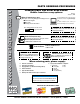
Operation and Parts Manual SERIES MODEL MTX70HF Tamping Rammer (HONDA GX100UKRB5 GASOLINE ENGINE) Revision #0 (03/08/12) To find the latest revision of this publication, visit our website at: www.multiquip.com THIS MANUAL MUST ACCOMPANY THE EQUIPMENT AT ALL TIMES.
proposition 65 warning page 2 — MTX70HF RAMMER • operation and parts manual — rev.
notes MTX70HF RAMMER • operation and parts manual — rev.
Table of Contents MTX70HF Rammer Proposition 65 Warning............................................ 2 Parts Ordering Procedures....................................... 5 Safety Information................................................. 6-9 Specifications......................................................... 10 General Information................................................ 11 Components........................................................... 12 Basic Engine......................................
www.multiquip.com Parts Ordering Procedures Ordering parts has never been easier! Choose from three easy options: order via internet (dealers only): best deal! Effective: January 1st, 2006 If you have an MQ Account, to obtain a Username and Password, E-mail us at: parts@multiquip. com. Order parts on-line using Multiquip’s SmartEquip website! ■ View Parts Diagrams ■ Order Parts ■ Print Specification Information To obtain an MQ Account, contact your District Sales Manager for more information.
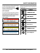
Safety Information Do not operate or service the equipment before reading the entire manual. Safety precautions should be followed at all times when operating this equipment. Failure to read and understand the safety messages and operating instructions could result in injury to yourself and others. Potential hazards associated with the operation of this equipment will be referenced with hazard symbols which may appear throughout this manual in conjunction with safety messages.
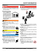
Safety Information geneRal saFeTy CauTion neveR operate this equipment without proper protective clothing, shatterproof glasses, respiratory protection, hearing protection, steel-toed boots and other protective devices required by the job or city and state regulations. alWays know the location of the nearest phone or keep a phone on the job site. Also, know the phone numbers of the nearest ambulance, doctor and fire department. This information will be invaluable in the case of an emergency.
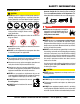
Safety Information engine saFeTy dangeR The engine fuel exhaust gases contain poisonous carbon monoxide. This gas is colorless and odorless, and can cause death if inhaled. Fuel saFeTy dangeR DO NOT add fuel to equipment if it is placed inside truck bed with plastic liner. Possibility exists of explosion or fire due to static electricity. The engine of this equipment requires an adequate free flow of cooling air.
Safety Information TRanspoRTing saFeTy CauTion NEVER allow any person or animal to stand underneath the equipment while lifting. NOTICE Before lifting, make sure that the equipment parts (hook and vibration insulator) are not damaged and screws are not loose or missing. Always make sure crane or lifting device has been properly secured to the lifting bail (hook) of the equipment. alWays shutdown engine before transporting. neveR lift the equipment while the engine is running.
specifications Overall Height Overall Width Over Length Shoe Size (W x L) Fuel Tank Capacity Lubrication Oil Capacity No. of Impacts Per Second Impact Force Impact Plate Stroke Operating Weight Table 1. Rammer Specifications 40.04 in. (1017 mm) 13.78 in. (350 mm) 28.1 in. (713 mm) 13.4 x 11.2 in. (340 x 285 mm) 2.1 qt. (2 liters) 0.86 qt. (0.82 liter) 10.7 - 11.5 2,855 lbf (12.7 kN) 2 - 3.2 in. (50 - 80 mm) 163.13 lbs. (74 kg) Measured Sound Power Level Guaranteed Sound Power Level Max.
general Information Definition of Tamping Rammer The Multiquip MTX70HF tamping rammer is a powerful compacting tool capable of applying a tremendous force in consecutive impacts to a soil surface. Its applications include soil compacting for road, embankments and reservoirs as well as backfilling for gas pipelines, water pipelines and cable installation work. The impact force of the MTX70HF levels and uniformly compacts voids between soil particles to increase dry density.
components 3 2 10 4 1 5 9 6 11 7 12 13 8 Figure 1. MTX70HF Rammer Figure 1 shows the location of the controls and components for the MTX70HF Tamping Rammer. The functions of each control is described below: 1. Combination (Throttle) Lever — Used to adjust engine speed (rpm). Move lever forward (SLOW) to reduce engine speed, move lever back toward operator (FAST) to increase speed. Always operate the rammer at full speed (rpm). 8.
basic engine Figure 2. Honda GX100 Engine The engine (Figure 2) must be checked for proper lubrication and filled with fuel prior to operation. Refer to the engine manufacturer's manual for detailed operation and service information. 1. Choke Lever — Normally used in starting the engine in cold weather conditions. In cold weather, turn the choke lever to the fully closed position. In warm weather, set the choke lever halfway or completely open. 2. Spark Plug — Provides spark to the ignition system.
inspection It is extremely important that this section be read carefully before attempting to operate the rammer. DO NOT use your rammer until this section is thoroughly understood. OIL LEVEL DIPSTICK Crankcase and Spring Cylinder Oil Bath This unit uses an oil bath lubrication system. Perform the following: 1. Check the oil level through the oil level sight glass (Figure 3) at the rear of the tamper foot. OIL FILL PLUG SIGHT GLASS OIL DRAIN PLUG Figure 5. Engine Oil Dipstick 2.
operation CAUTION Failure to understand the operation of the Tamping Rammer could result in severe damage to the unit or personal injury. 3. Grip the starter rope handle (Figure 8) and pull it until you feel a slight resistance. Then pull sharply and quickly. Return the handle to the starter case before releasing. Initial Startup When starting the MTX70HF Tamping Rammer perform the following: 1. Slide the throttle lever from the stop to the idle position ( ) (Figure 6).
operation operation Stopping The Engine 1. To start the rammer tamping action, move the throttle lever (Figure 9) quickly from IDLE to the START ( ) position. DO NOT move the throttle lever slowly as this may cause damage to the clutch or spring. 1. Move throttle lever quickly from the START to IDLE position (Figure 6) and run the engine for three minutes at low speed. After the engine cools, move the throttle lever to the STOP position (Figure 10).
maintenance Perform the scheduled maintenance procedures as indicated: DAILY Thoroughly remove dirt and oil from the engine and control area. Clean or replace the air cleaner elements as necessary. Check and retighten all fasteners as necessary. Check the spring box and bellows for oil leaks. Repair or replace as needed. EVERY 50 HOURS PRIMARY ELEMENT Figure 12. Air Cleaner Primary Element EVERY 200 HOURS Remove the fuel filter cap and clean the inside of the fuel tank (Figure 11).
troubleshooting Troubleshooting (engine) symptom possible problem solution Spark plug bridging? Check gap, insulation or replace spark plug. Carbon deposit on spark plug? Clean or replace spark plug. Short circuit due to deficient spark plug insulation? Check spark plug insulation, replace if worn. Improper spark plug gap? Set to proper gap. Fuel reaching carburetor? Check fuel line. Water in fuel tank? Flush or replace fuel tank. Fuel filter clogged? Replace fuel filter.
troubleshooting Troubleshooting (engine) - continued symptom Weak in power, compression is proper and does not misfire. Weak in power, compression is proper but misfires. Engine overheats. Rotational speed fluctuates. Recoil starter malfunctions. (if applicable) Starter malfunctions. possible problem Air cleaner dirty? Clean or replace air cleaner. Improper level in carburetor? Check float adjustment, rebuild carburetor. Defective spark plug? Clean or replace spark plug.
troubleshooting symptom Engine runs but rammer jumps erratically or not at all. Troubleshooting (Rammer) possible problem Operating speed of throttle lever is incorrectly set? Oil in excess? Clutch slips? Spring Failure? Speed of engine improper? Soil over-compacted? solution Set throttle lever to correct position. Drain excess oil. Bring to correct level. Replace or adjust clutch. Replace spiral spring. Adjust engine speed to correct operating RPM setting. Shut down machine and test soil.
notes MTX70HF RAMMER • operation and parts manual — rev.
Explanation of Code in Remarks Column The following section explains the different symbols and remarks used in the Parts section of this manual. Use the help numbers found on the back page of the manual if there are any questions. NOTICE The contents and part numbers listed in the parts section are subject to change without notice. Multiquip does not guarantee the availability of the parts listed. saMple paRTs lisT no. 1 2% 2% 3 4 paRT no. paRT naMe QTy. ReMaRks 12345 BOLT .....................1 .....
Suggested Spare Parts MTX70HF RAMMER WITH HONDA GX100UKRB5 ENGINE 1 TO 3 UNITS Qty. P/N Description 1............956100062.............THROTTLE WIRE 3............366010070.............PRIMARY ELEMENT, AIR CLEANER 3............366010080.............SECONDARY ELEMENT, AIR CLEANER1 1............366350010.............CAP ASSY., FUEL TANK 3............9805655777...........SPARK PLUG 1............954406010.............STRAINER, FUEL TANK 1............28462Z0DV03........
nameplates and decals 4 1 7 13$ 2 3 5 13$ 6723 13$ 6 11 02'(/ 6(5,$/ 12 A (DECAL SET) 8 series quick manual (QJLQH 2LO 8VH 6$( : 6( RU KLJKHU JUDGH PRWRU RLO 5$00,1* &
nameplates and decals NO. PART NO. PART NAME QTY. REMARKS A 920900040 DECAL SET . .....................................................1................INCLUDES ITEMS W/# 1 920212910 DECAL: OPERATION 1 2# DECAL: AIR CLEANER 1 3# DECAL: LEVER OPERATION 1 4# DECAL: MAX SPEED 1 5# DECAL: MACHINE STOP 1 6# DECAL: EC NOISE REQ 1 7# DECAL: ANTI-VIB HANDLE 1 8 920212540 QUICK MANUAL 1 11 DECAL: NAMEPLATE . ......................................1................
crankcase and engine assy 48 45 46 49 46 49 36-4 36-3 36-2 70-1 70-2 70-3 36-1 36 36-7 65 69 36-9 36-8 41 42-1 42-2 42-3 36-5 54-1 54-2 32-1 32-1 50 54 57-2 57-1 73 39 37 40 43-2 38 23 43-1 51 35 72 51 31 50 24 25-2 25-1 33 47 2 5 4 28 26 14 A 101 6 15 13 20 19 59 1 58 61 55 56 53 17 916 7 60 29 2 A 106 111 34 56 11 10 12 75 74 61 55 71 62 58 63 57-2 57-1 3 76 21 page 26 — MTX70HF RAMMER • operation and parts manual — rev.
crankcase and engine assy NO. 1 2$ 3 4 5 6 7 9 10 11 12 13 14 15 16 17 19 20 21 23 24 25-1 25-2 26 28 29 31 32-1 32-2 33 34 35 36 36-1# 36·2# 36-3# 36-4# 36-5# 36-7# 36-8# 36-9# 37 38 39 40 41 PART NO.
crankcase and engine assy 48 45 46 49 46 49 36-4 36-3 36-2 70-1 70-2 70-3 36-1 36 36-7 65 69 36-9 36-8 41 42-1 42-2 42-3 36-5 54-1 54-2 32-1 32-1 50 54 57-2 57-1 73 39 37 40 43-2 38 23 43-1 51 35 72 51 31 50 24 25-2 25-1 33 47 2 5 4 28 26 14 A 101 6 15 13 20 19 59 1 58 61 55 56 53 17 916 7 60 29 2 A 106 111 34 56 11 10 12 75 74 61 55 71 62 58 63 57-2 57-1 3 76 21 page 28 — MTX70HF RAMMER • operation and parts manual — rev.
crankcase and engine assy NO. 42-1 42-2 42-3 43-1 43-2 45 46 47 48 49 50 51 53 54 55 56 57-1 57-2 58 59 60 61 62 63 64 65 69@ 70-1 70-2 70-3 71 72 73 74 75 76 79 101 106 111 PART NO.
guide cylinder assy 2 32 1 20 3 9 22 21 24 12 8 27 18 17 14 28 25 29 26 13 15 16 23 29 9 27 28 25 26 7 4 6 5-2 5-1 24 31 51 30 52 53 page 30 — MTX70HF RAMMER • operation and parts manual — rev.
guide cylinder assy NO. 1 2 3 4 5-1 5-2 6 7 8 9 12 13 14 15 16 17 18 20 21 22 23 24 25 26 27 28 29 30 31 32 51 52 53 PART NO.
foot assy 2 3 6 2 3 1 4 5 page 32 — MTX70HF RAMMER • operation and parts manual — rev.
foot assy NO. 1 2 3 4 5 6 PART NO. 8511S 0211121409 030212300 009110034 009110035 363343390 PART NAME FOOT ASSY 285 NYLON NUT M12 WASHER, LOCK M12 BOLT, SQUARE NECK 12X65 BOLT, SQUARE NECK 12X95 GRIP HANDLEBAR QTY. 1 4 4 2 2 1 REMARKS MTX70HF RAMMER • operation and parts manual — rev.
fuel tank and handle assy 9 8 202 201 54 51 53 10 56 14 22 55 15 16 A 18 17 3 12 11-2 11-1 4-1 4-2 6 40 12 11-2 11-1 43 7 13 11-2 11-1 5 41 A 43 42 20 101 19 103 4-2 4-1 20 41 42 102 1 2-2 2-1 page 34 — MTX70HF RAMMER • operation and parts manual — rev.
fuel tank and handle assy NO. 1 2-1 2-2 3 4-1 4-2 5 6 7 8* 9 10 11-1 11-2 12 13 14 15 16 17 18 19 20 22 40 41# 42# 43# 51 53 54 55 56 101 102 103 201 202 PART NO.
COMBINATION LEVER assy page 36 — MTX70HF RAMMER • operation and parts manual — rev.
COMBINATION LEVER assy NO. A 1@ 2@ 3@ 4@ 5@ 6@ 7@ 8@ 9@ 10 11@ 12@ 13@ 14@ PART NO. 956200110 366349430 366010310 366010190 366010200 366010210 366010220 020408050 959407650 366010320 956100062 094010051 094010052 050200150 050200110 PART NAME QTY. REMARKS COMB. LEVER....................................................1................INCLUDES ITEMS W/@ FUEL COCK 1 LEVER 1 SLlDER 1 END CAP 1 WIRE CAP 1 BOLT AND WASHER SET 1 NUT M8, H=5 2 SOCKET HEAD SCREW W/ TH.
tools assy page 38 — MTX70HF RAMMER • operation and parts manual — rev.
tools assy NO. PART NO. 1 981010400 2 983010060 3 983910030 4 009110044 5 983910021 6 983010042 7 983910010 PART NAME QTY. CLUTCH PULLER A 1 CLUTCH MOUNTER 1 PISTON ROD HOLDER 1 SOCKET HEAD BOLT 8X50 (FULL THREAD) CRANK GEAR REMOVER 2 CLUTCH PULLER B 1 SPRING CYLINDER REMOVER 1 PISTON END REMOVER 1 REMARKS MTX70HF RAMMER • operation and parts manual — rev.
honda Gx100krb5 engine — cylinder barrel assy. page 40 — MTX70HF RAMMER • operation and parts manual — rev.
honda Gx100krb5 engine — cylinder barrel assy. NO. 1 2@ 3@ 5 6 7 8 9 10 11 12@ 13 14 15 16 PART NO. 12000Z0D405 12201Z0D305 12204Z0D305 12311Z0D000 12355Z0D000 12365Z0D000 15571Z0DV71 15572ZM7000 15721Z0DV70 90014952000 91202KJ9003 93500030050A 9805655777 15171Z0DV00 90008ZM7000 PART NAME QTY. REMARKS BARREL ASSY., CYLINDER .............................1................INCLUDES ITEMS W/@ GUIDE ASSY., EX VALVE (O.S.) 1 GUIDE, INLET VALVE (O.
honda Gx100krb5 engine — CRANKCASE COVER assy. page 42 — MTX70HF RAMMER • operation and parts manual — rev.
honda Gx100krb5 engine — CRANKCASE COVER assy. NO. 1 3 4# 5@ 9@ 10 11 12 13@ 14 15@ 16@ 17@ 18 19 21@ 24 PART NO. 11300Z0D409 15600ZM7003 15625ZE1003 16510ZL8000 16531ZE1000 16541Z0D000 957010602500 90131ZE1000 90451ZE1000 90601ZE1000 90602ZE1000 91202KJ9003 58176 9425108000 9430108200 91001Z0DV01 91231891003 PART NAME QTY. REMARKS COVER ASSY., CRANK CASE . ........................1................INCLUDES ITEMS W/@ OIL FILLER CAP ASSY . ...................................2................
honda Gx100krb5 engine — CRANKSHAFT assy. page 44 — MTX70HF RAMMER • operation and parts manual — rev.
honda Gx100krb5 engine — CRANKSHAFT assy. NO. 3 6@ PART NO. 13310Z0DV70 91001Z0DV01 PART NAME QTY. REMARKS CRANK SHAFT COMP . ....................................1................INCLUDES ITEM W/@ BEARING, RADIAL BALL 1 MTX70HF RAMMER • operation and parts manual — rev.
honda Gx100krb5 engine — PISTON/CONN. ROD assy. page 46 — MTX70HF RAMMER • operation and parts manual — rev.
honda Gx100krb5 engine — PISTON/CONN. ROD assy. NO. PART NO. PART NAME QTY. REMARKS 1 13010Z0D003 RING SET, PISTON 1 2 13101Z0D000 PISTON 1 3 13111ZE0000 PISTON PIN 1 4 13200Z0D000 CONNECTING ROD ASSY. . .............................1................INCLUDES ITEM W/@ 4 13200Z0D305 CONNECTING ROD ASSY. . .............................1................UNDERSIZE INCLUDES ITEM W/@ 5@ 90001ZM7000 CONNECTING ROD BOLT 2 6 90551ZE0000 CLIP, PISTON PIN 13MM 2 MTX70HF RAMMER • operation and parts manual — rev.
honda Gx100krb5 engine — camshaft assy. page 48 — MTX70HF RAMMER • operation and parts manual — rev.
honda Gx100krb5 engine — camshaft assy. NO. 1 2 3 4 5 6 7 8 9 10 11 12 13 14 PART NO. 14320Z0D010 14324Z0D000 14400Z0D003 14431Z0D000 14441Z0D000 14461ZL8000 14711Z0D000 14721Z0D000 14751Z0D000 14771ZM3010 90012333000 90206001000 91301ZM0V31 12209KT7013 PART NAME PULLEY, COMP.
honda Gx100krb5 engine — recoil starter assy. page 50 — MTX70HF RAMMER • operation and parts manual — rev.
honda Gx100krb5 engine — recoil starter assy. NO. 1 2@ 3@ 4@ 5@ 6@ 7@ 8@ 9@ 10@ 11@ 12@ 13 PART NO. 28400Z0DV04ZA 28410Z0DV02ZA 28421Z0DV02 28422ZG0W02 28433ZG0W02 28441ZW9003 28442ZH8003 28461ZH8013 28462Z0DV03 28467Z0DV02 28468Z0DV02 90003ZH8003 957010600800 PART NAME QTY. REMARKS RECOIL STARTER ASSY . ................................1................
honda Gx100krb5 engine — fan cover assy. page 52 — MTX70HF RAMMER • operation and parts manual — rev.
honda Gx100krb5 engine — fan cover assy. NO. 1 3 PART NO. PART NAME 19610Z4ES30ZA FAN COVER CP 90014952000 BOLT, FLANGE 6X14 (CT200) QTY. 1 4 REMARKS MTX70HF RAMMER • operation and parts manual — rev.
honda Gx100krb5 engine — carburetor assy. page 54 — MTX70HF RAMMER • operation and parts manual — rev.
honda Gx100krb5 engine — carburetor assy. NO. 1@ 2@ 3@ 4@ 5@ 6@ 7@ 8@ 9 10@ 11@ 12@ 13 14 15 16@ 19@ 20@ 21@ 22 PART NO. 16010Z0DV21 16011ZE0005 16013ZG0811 16015Z0DV21 16016Z0DV21 16024ZB9005 16028ZW6611 16044Z0DS01 16100Z4EW51 16124ZE0005 16166Z0D003 16199Z0DV21 16211Z0D000 16212Z0DV20 16221ZG0801 938920401208 950030502131 99101ZG00580 99204ZE00350 90602921000 PART NAME QTY.
honda Gx100krb5 engine — air cleaner assy. page 56 — MTX70HF RAMMER • operation and parts manual — rev.
honda Gx100krb5 engine — air cleaner assy. NO. 8 10 11 14 PART NO. 17228Z0DV21 90042Z4ES30 9405005000 17410Z0DS00 PART NAME PACKING, AIR CLEANER STUD BOLT 5X95 FLANGE NUT 5MM ELBOW, AIR CLEANER QTY. 1 2 2 1 REMARKS MTX70HF RAMMER • operation and parts manual — rev.
honda Gx100krb5 engine — muffler assy. page 58 — MTX70HF RAMMER • operation and parts manual — rev.
honda Gx100krb5 engine — muffler assy. NO. 1 2 3 4 5 6 PART NO. 18310Z0DV20 18321Z0DV22 18381Z0D000 90014952000 90048Z0DV00 90343ZE6000 PART NAME MUFFLER COMP. MUFFLER PROTECTOR GASKET, MUFFLER BOLT, FLANGE 6X14 (CT200) STUD BOLT 6X78 NUT, SELF-LOCK 6MM QTY. 1 1 1 3 2 2 REMARKS MTX70HF RAMMER • operation and parts manual — rev.
honda Gx100krb5 engine — flywheel ignition assy. page 60 — MTX70HF RAMMER • operation and parts manual — rev.
honda Gx100krb5 engine — flywheel ignition assy. NO. 1 3 4 7 9 10 11 12@ PART NO. 13331ZM7000 30564ZA5000 131110Z0D003 90022888010 9405012000 28451Z0DV03 30500Z0DV02 30700Z0DV01 PART NAME QTY. REMARKS WOODRUFF KEY 25X18 1 GROMMET, CORD 1 FLYWHEEL COMP 1 FLANGE BOLT 6X20 2 FLANGE NUT M12 1 STARTER PULLEY 1 IGNITION COIL ASSY . .....................................1................INCLUDES ITEM W/@ TERMINAL ASSY 1 MTX70HF RAMMER • operation and parts manual — rev.
honda Gx100krb5 engine — control assy. page 62 — MTX70HF RAMMER • operation and parts manual — rev.
honda Gx100krb5 engine — control assy. NO. 3 4 5 6@ 8 9 10@ 11@ 12@ 15 17 19 20@ PART NO. 16555Z0DV20 16561Z0DV20 16562Z0DV20 16594883010 90014952000 90015ZE5010 90605230000 92301050220A 0043504060 9405006000 16550Z0DV21 16500Z4ES30 940010500005 PART NAME QTY. REMARKS GOVERNOR ROD 1 GOVERNOR SPRING 1 SPRING, THROTTLE RETURN 1 HOLDER, WIRE 1 BOLT, FLANGE 6X14 (CT200) 2 BOLT, GOVERNOR ARM 1 CIR CLIP 1 BOLT 5X20 1 SCREW 4X6 1 FLANGE NUT 6MM 1 GOVERNOR ARM 1 CONTROL ASSY . ....................................
honda Gx100krb5 engine — labels assy. page 64 — MTX70HF RAMMER • operation and parts manual — rev.
honda Gx100krb5 engine — labels assy. NO. 2 4 6 9 14 PART NO. 87521ZODV02 87516Z0JOOO 87601Z4EW50 87539Z0JOOO 89216130690 PART NAME LABEL, TRADE MARK MARK, OPERATOR CAUTION MARK, TYPE (KRBF) MARK, EX. CAUTION WRENCH, SPARK PLUG QTY. 1 1 1 1 1 REMARKS MTX70HF RAMMER • operation and parts manual — rev.
Terms and Conditions of Sale — Parts payMenT TeRMs 5. Parts must be in new and resalable condition, in the original Multiquip package (if any), and with Multiquip part numbers clearly marked. 6. The following items are not returnable: Multiquip reserves the right to quote and sell direct to Government agencies, and to Original Equipment Manufacturer accounts who use our products as integral parts of their own products. a. speCial eXpediTing seRviCe Terms of payment for parts are net 30 days.
notes MTX70HF RAMMER • operation and parts manual — rev.
Operation and Parts Manual HERE’S HOW TO GET HELP PLEASE HAVE THE MODEL AND SERIAL NUMBER ON-HAND WHEN CALLING United StateS Multiquip Corporate Office 18910 Wilmington Ave. Carson, CA 90746 Contact: mq@multiquip.com MQ Parts Department Tel.