OPERATION MANUAL MODELS SP403016 SP403020 SP403026 SP403030 PAVEMENT SAW (DEUTZ F2L2011 DIESEL ENGINE) Revision #0 (01/22/09) To find the latest revision of this publication, visit our website at: www.multiquip.com THIS MANUAL MUST ACCOMPANY THE EQUIPMENT AT ALL TIMES.
PROPOSITION 65 WARNING Engine exhaust and some of its constituents, and some dust created by power sanding, sawing, grinding, drillingandotherconstructionactivities contains chemicals known to the State of California to cause cancer, birth defects and other reproductive harm. Some examples of these chemicals are: Leadfromlead-basedpaints. Crystallinesilicafrombricks. Cementandothermasonryproducts. Arsenicandchromiumfromchemically treatedlumber.
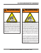
SILICOSIS/RESPIRATORY WARNINGS WARNING WARNING SILICOSIS WARNING RESPIRATORY HAZARDS Grinding/cutting/drilling of masonry, concrete, metal and other materials with silica in their composition may give off dust or mists containing crystalline silica. Silica is a basic component of sand, quartz, brick clay, granite and numerous other minerals and rocks. Repeated and/or substantial inhalation of airborne crystalline silica can cause serious or fatal respiratory diseases, including silicosis.
TABLE OF CONTENTS SP4030 Multiquip Saw Proposition 65 Warning ........................................... 2 Silicosis/Respiratory Warnings ................................ 3 Table of Contents .................................................... 4 Training Checklist .................................................... 6 Daily Pre-Operation Checklist ................................. 7 Safety ................................................................... 8-9 Rules and Regulations .......................
NOTES MQ SP4030 SAW • OPERATION MANUAL — REV.
TRAINING CHECKLIST TRAINING CHECKLIST This checklist lists the minimum requirements for machine maintenance and operation. Please feel free to detach it and make copies. Use this checklist when training a new operator or use as a review for more experienced operators. Training Checklist No. Description 1 Read operator’s manual completely. 2 Machine layout, location of components, checking of engine and hydraulic oil levels. 3 Fuel system, refueling procedure. 4 Operation of spray and lights.
DAILY PRE-OPERATION CHECKLIST DAILY PRE-OPERATION CHECKLIST Daily Pre-Operation Checklist 1 Hardware and damage check. 2 Engine oil level. 3 Hydraulic oil level. 4 Condition of blade. 5 Safety stop switch operation. 6 Braking control operation. COMMENTS: MQ SP4030 SAW • OPERATION MANUAL — REV.
SAFETY FOR YOUR SAFETY AND SAFETY OF OTHERS! HAZARD SYMBOLS Safety precautions should be followed at all times when operating this equipment. Failure to read and understand the safety messages and operating instructions could result in injury to yourself and others. Potential hazards associated with the operation of this equipment will be referenced with hazard symbols which appear throughout this manual, and will be referenced in conjunction with safety message alert symbols.
SAFETY CAUTION — Rotating Blade Rotating blade can cut and crush. Keep hands and feet clear. CAUTION — Overspeed Conditions NEVER tamper with the factory setting of the engine governor. Personal injury and equipment damage can result if operating in speed ranges above the maximum allowable. CAUTION — Accidental Starting Hazards Accidental starts can cause severe injury or death. ALWAYS place the equipment ON/OFF switch in the OFF position when the equipment is not in use.
RULES AND REGULATIONS WARNING — Read This Manual Failure to follow instructions in this manual may lead to serious injury or even DEATH! This equipment is to be operated by trained and qualified personnel only! This equipment is for industrial use only. GENERAL SAFETY DO NOT operate or service this equipment before reading this entire manual. This equipment should not be operated by persons under 18 years of age.
RULES AND REGULATIONS NEVER use fuel as a cleaning agent. ALWAYS store the equipment in a clean, dry location out of the reach of children. NEVER run engine without air cleaner or filter. Service air cleaner at recommended service intervals to prevent egine damage. Severe engine damage may occur. NEVER leave the equipment unattended with the engine running. Turn off engine when unattended. CAUTION must always be observed while servicing this equipment. Rotating parts can cause injury if contacted.
RULES AND REGULATIONS Always store equipment properly when not being used. Equipment should be stored in a clean, dry location out of the reach of children. When storing the saw in freezing weather, blow out the water lines to prevent damage to components in the water delivery system. DON'T POLLUTE! Waste oils and other chemicals must be disposed of in a manner consistent with local and state environmental protection regulations.
RULES AND REGULATIONS SAW LIFTING AND LOADING SAFETY CAUTION — Lifting Saw This saw is very heavy. Use proper heavy lifting procedures and DO NOT attempt to lift by the guards. TOWING SAFETY PRECAUTIONS (TRAILER USAGE) CAUTION — Transporting Saw Conform to Department of Transportation (DOT) Safety Towing Regulations before transporting saw on public roads. DANGER — Do Not Stand Upder Saw NEVER stand under or allow anyone else to stand under the saw while it is being lifted.
RULES AND REGULATIONS BATTERY The battery contains acids that can cause injury to the eyes and skin. To avoid eye irritation, ALWAYS wear safety glasses or face shielding. Use well insulated gloves when picking the battery up. Use the following guidelines when handling the battery. DO NOT drop the battery. Any impact to the battery may cause it to explode. DO NOT expose the battery to open flames, sparks, lit cigarettes, etc. The battery contains combustible gases and liquids.
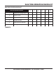
DIMENSIONS See Figures 1 and 2 and Table 1 for saw dimensions. H L G K F I J Figure 1. Chassis and Dimensions — Bottom View TABLE 1. CHASSIS & DIMENSIONS REFERENCE LETTER DIMENSIONS in. (mm) DESCRIPTION A Max Height (Raised/Front Pointer up) 71 in. (1803 mm) B Max Handle Bar Height 47 in. (119 mm) C Max Length (Handle Bars Installed & Front Pointer fully raised) 88 in. (2235 mm) D Length (Handle Bars not Installed & Front Pointer fully raised) 63 in.
SPECIFICATIONS E C D A B Figure 2. Chassis and Dimensions — Side View Blade Shaft Assembly Blade Shaft Bearings Blade Shaft Diameter Arbor Diameter Blade Flanges Blade Flange Sizes Drive Belt Max. Blade Raise Height Blade Mounting Max. Blade Diameter Max. Depth of Cut Blade Guard Capacity Blade Guard Blade Raise-Lower Water Control Water Distribution Table 2. Blade and Shaft Specifications Oil bath design, fully enclosed housing Oil bath lubricated 2-3/8 in. (60mm) 1 in. (25.
ENGINE SPECIFICATIONS Engine Manufacturer Model Max RPM Horsepower/Max kW Peak Torque Fuel Fuel Capacity Air Filter Oil Capacity Engine Coolant Transmission Pump Wheel Motors Travel Speed Brakes Wheels Rear Wheels Front Table 3. Engine/Motor Specifications Deutz F2L 2011 3000 31.3 HP/23.0 kW 66.3 lb./ft. (90 Nm) Diesel 6.0 gallons/22.7L Dual element radial seal with integral turbo pre-cleaner 7 Qts. (6.6L) Oil to Air Table 4.
INTENDED USE / FAMILIARIZATION INTENDED USE FEATURES Operate the SP4030 Multiquip Saw, tools and components in accordance with the manufacturer’s instructions. Use of any other tools for stated operation is considered contrary to designated use. The risk of such use lies entirely with the user. The manufacturer cannot be held liable for damages as a result of misuse. ■ Tri-position handlebars allow for 3-position adjustment for optimal maneuverability.
SERIAL TAG INFORMATION 1 2 MODEL SERIAL NO. Figure 3. Serial Tag/Locations SERIAL TAG The serial tag contains the model number and serial number of the saw. The information details all parts that were included with the saw when it was shipped from the factory, as well as the date of manufacture. Record these numbers, in case you need to contact the manufacturer for information or service in the future.
CONTROLS AND INDICATORS 14 5 16 7 3 6 17 4 13 12 8 2 9 11 1 10 18 15 Figure 4. Controls and Indicators Figures 4 and 5 show the location of the controls, indicators and general maintenance parts. The function of each control, indicator or maintenance part is explained below: 7. Light Switch – When activated, turns on light. Lights offer better visibility when working indoors. 8. FNR Handle – Use to engage the saw in a forward or backward direction.
COMPONENTS 1 15 2 14 16 17 13 4 21 3 18 6 12 11 10 9 8 5 20 22 19 7 Figure 5. Components 1. Front Pointer Assembly 12. Documentation Box 2. Blade Wrench 13. Rightside Water On/Off Control Valve 3. Blade shaft Pulley Guard 14. Light Assembly 4. Blade shaft Assembly 15. Engine Assembly 5. Blade Flange 16. Engine Fuel Filler Cap 6. Front Axle Assembly 17. Control and Indicator Panel 7. Left Wheel Motor 18. Handlebars 8. Brake Cylinder 19. Rear Access Panel 9.
BASIC ENGINE INFORMATION 13 6 16 12 8 18 11 15 9 2 3 10 4 14 7 1 17 5 Figure 6. Basic Engine Components BASIC ENGINE COMPONENTS 9. V-belt Tension Adjustment — This bolt provides means to adjust the V-belt tension at the alternator bracket. The following refer to basic engine components and their functions that an operator may need to reference. The manufacturer’s engine manual provides further instructions and details of operation and servicing.
CHOOSING PROPER BLADE SIZE CHOOSING PROPER BLADE SIZE Proper blade selection is a product of: ■ Understanding the capability of your saw ■ Understanding the specifications of the engine ■ Understanding the blade shaft speed of your saw ■ Understanding diamond blade operating limitations ■ The depth of cut required ■ Cutting conditions ■ Desired cutting performance requirements Engine (RPM) and Surface Feet per Minute (SFPM) Speeds This saw uses a belt drive system to propel the diamond blade.
CHOOSING PROPER BLADE SIZE Blade RPM vs. Surface Feet Per Minute (SFPM) CAUTION When choosing a blade for your cutting conditions, follow the blade manufacturer’s recommendations. Match the blade speed (blade shaft RPM) to the recommended blade surface feet per minute (SFPM). See Table 8. Verify the engine start switch is OFF before removing or installing a blade. Tighten the 5/8" blade-mounting bolt to 125-175 ft. lbs. of torque.
SPECIFIC TOOLS / SAW BLADES SPECIFIC TOOLS TO BE USED This saw is to use tools (blades) as follows: Steel core segmented or continuous diamond rim cutting wheel Any other type of tool is not to be used. SAW BLADES WARNING — Inspect Diamond Blade Failure to thoroughly inspect the diamond blade (Figure 8) for operational safety could result in damage to the blade or the saw and may cause injury to the user or others in the operating area. Discard damaged or worn blades and replace with fresh blade.
INSTALLING THE BLADE INSTALLING THE BLADE The blade can be mounted on either side of the saw to accomodate different cutting jobs. With the proper sized blade selected, reference the following procedure to install the new blade. Ensure the flange faces are kept clean and smooth as well as the inside diameter of the blade shaft. 1. Raise the saw so the blade will clear the ground when installed. 2. Remove the blade flange bolt.
INSTALLING THE BLADE CAUTION — Improper Torque An improperly torqued mounting bolt can cause the inside diameter of the blade, blade shaft, and flange bushing to quickly wear. This can result in poor cutting characteristics or premature failure of these parts requiring replacement and machine “downtime.” 2 Stacking Blades for Wide Cuts Combining, or stacking blades together to make wide cuts requires an optional bushing extension kit.
BLADE GUARDS BLADE GUARD The blade guards can be mounted on either side of the saw to accomodate different cutting jobs. The saw utilizes a tapered blade guard mounting clip that, during operation, settles in the taper by the weight of the guard locking itself into place providing a rigid, rattle-free fit. 2.
BLADE GUARDS Installing a Blade Guard: INSTALLING THE FLANGE GUARD 1. Slide the blade guard straight downward to engage the tapered mounting clip (Figure 16). The flange guard protects the blade flange when not in use. 1. Slide the flange guard onto the guard mounting tab on the frame (Figure 18). 2. Verify that the blade flange not in use is secured to the blade shaft by tightening the mounting bolt. Figure 16. Tapered Mounting Clip 2. Connect the water delivery hose to the blade guard (Figure 14).
WATER DELIVERY SYSTEMS WATER DELIVERY SYSTEM (OPTION) CAUTION When storing the saw where temperatures may drop below freezing, blow out the water lines to prevent damage to the water delivery system. 1. Connect the water supply hose to the water inlet (garden hose) fitting on the left side of the saw (Figure 5, Item 21). 2. Verify that the water hose on the saw is connected to the blade guard (Figure 14), and that the water hoses or tubes are pointed into both blade flanges. 3.
BATTERY BATTERY SETUP WARNING — Battery hazards Always recharge the battery in a wellventilated area to avoid risk of a dangerous concentration of combustible gases. Battery electrolyte contains corrosive, toxic chemical (dilute sulfuric acid). Avoid contact with eyes and skin. Figure 19. Battery and Battery Box WARNING — Shock hazards Disconnect battery cables before inspecting electrical system and never “spark” battery terminals to test for charge.
FUELING THE SAW FUELING THE SAW Priming the Fuel System This saw features a 6 gallon, clear, molded plastic fuel tank for ease of checking the fuel level. It has a central drain and a shutoff valve. The fuel tank cap is located at the front of the control panel console and a fuel gauge tube is featured on the front of the console. The saw utilizes a fuel primer bulb (Figure 21, item A) or button (item B), when fueling the saw for the first time or refilling after running out of fuel.
COLD WEATHER OPERATION/POINTER ADJUSTMENT COLD WEATHER OPERATION Block Heaters CAUTION — Block Heaters DO NOT leave optional block heaters plugged in for extended periods when temperatures may rise above 20oF (-6.67oC). The oil could “cook” inside the crankcase and damage to the engine could result. 3. Adjust the pointer rod (Item 5), by loosening the lock knob (Item 4).
RAISE-LOWER CONTROLS RAISE - LOWER CONTROLS SETTING THE DEPTH STOP The MQ SP4030 saw uses a 24-volt motor and hydraulic cylinder to raise and lower the saw. The raise-lower function is controlled by the operator through a 3-position toggle switch on the raise-lower control handle located on the operator’s control panel. The SP4030 saw uses a controlled depth stop to position and set the blade at a desired cut depth (Figure 26). Figure 24. Raise-Lower Control Toggle Switch 1.
RAISE-LOWER CONTROLS/WHEEL DRIVE SYSTEM To control the depth of cut with saw running and blade mounted: 1. Set depth indicator as outlined on previous page. 2. Loosen pointer knob (Figure 27, item 1). 3. Rotate pointer to desired depth (Figure 27, item 2). 4. Re-tighten pointer knob to lock-in cutting depth. WHEEL DRIVE SYSTEM The 4030 Series features a cable-controlled hydraulic powered gear motor system with infinite Forward-NeutralReverse (F-N-R) speed adjustment.
OPERATION STARTING AND STOPPING THE ENGINE WARNING DO NOT leave the saw unattended while the engine is running. NEVER start, park, or leave the saw unattended on a slope. CAUTION Allow the engine to warm up before increasing engine speed. DO NOT stop the engine abruptly when hot. Reduce the throttle to idle and allow the engine to run one or two minutes before turning the ignition switch off. This allows the engine to cool down preventing damage to the Turbo charger. Starting the Engine 1. 2. 3. 4. 5. 6.
OPERATION Stopping the Engine In case of an EMERGENCY, push the RED EMERGENCY-STOP BUTTON to stop all functions (Figure 31). Engine will not crank when emergency stop button is depressed. OPERATING SYNOPSIS BEFORE STARTING — Check all fluid levels. Secure blade firmly to blade shaft. Make sure all protective guards are in place and properly mounted. Wear eye, ear protection and protective clothing. WATER SUPPLY — Connect water supply to water inlet. Move water ON/OFF CONTROL to ON position.
LOADING AND TRANSPORTING LOADING, UNLOADING AND TRANSPORTING THE SAW Loading and Unloading Lifting Point The convenient single point for lifting the saw with a hoist is located above the engine (Figure 33). WARNING When LOADING, UNLOADING, or when on a STEEP SLOPE, the engine MUST BE at 1800 RPM or above to prevent loss of control. Tie-Down Points The saw is provided with holes at each corner of the lower frame for easy tie-down during transportation. See Figure 32. CAUTION Figure 33.
MAINTENANCE MAINTENANCE Maintenance Schedule WARNING Certain maintenance operations or machine adjustments require specialized knowledge and skill. Attempting to perform maintenance operations or adjustments without the proper knowledge, skills or training could result in equipment damage or injury to personnel. If in doubt, consult your dealer.
MAINTENANCE Never blow dirt out with compressed air or try to clean with fluids. Damage can occur to the filter, and if reinstalled, can result in damage to the engine. CAUTION — Air Filters ENGINE This saw features a 30 HP DEUTZ Tier II diesel engine, F2L2011. Complete engine service details and recommendations can be found in the engine manufacturer’s manual included with the saw. See Figure 37. Safety air filters are NOT intended to be used for primary air filtration.
MAINTENANCE Checking Engine Oil Oil Filter (125 Hours) 1. Check engine oil level daily before starting the engine. 1. Replace the engine oil filter (Figure 38) every oil change or 125 hours. Refer to your engine manual for specific details to perform this operation. 2. When checking or adding oil, place the machine so the engine is level. 3. Pull the engine oil dipstick from its holder (Figure 37, Item 10). 4. Determine if engine oil is low.
MAINTENANCE Fuel Filter (200 Hours) LUBRICATION ■ Replace the engine fuel filter (Figure 39) every 500 hours. Refer to your engine manual for specific details to perform this operation. This saw has many service-saving features, including fully enclosed oil bath lubricated blade shaft bearings that require no daily lubrication. This saw has 5 grease fittings. See Figure 40. Grease these fittings every 125 hours of operation with a premium grade waterproof E.P. (extreme pressure) grease.
MAINTENANCE COOLING SYSTEM BATTERY/CHARGING SYSTEM The Deutz 2011 Series engine uses a robust, heavy duty oil cooler system to cool the engine. The cooling system will benefit from periodic inspection and cleaning. 1. Disconnect the air intake hose. Remove the three nuts and torx screws (Figure 41, Item 1). 2. Remove 3 bolts that mount the air filter bracket to the engine (item 2) and the two bolts holding the lifting bale (Item 3). 3.
MAINTENANCE Replacing the Battery Removable Guards and Access Panels For ease of service access, the guards and access panels shown in Figure 44 are removable. 3 4 Figure 42. Battery Location 1. Remove rear access panel. 2. Disconnect both negative battery cables first, then disconnect both positive battery cables to prevent arcing. 3. Remove top battery retainer clip (Figure 43, Item A). 4. Remove lower battery retainer (Figure 43, Item B). 5. Carefully slide battery out of tray.
MAINTENANCE Belts and Pulleys This saw uses a 6 groove 3V X 500 optibelt for its drive belt system and a hydrostatic pump belt (AX-35). 1 2 2 1 3 5 4 3 1. 2. 3. 4. 5. Engine Mount Adjustment Screw Engine Mount Adjustment Nut Turnbuckle Pivot Screw Engine Mount Pivot screw Turnbuckle 1. Blade Shaft Drive Belt 2. Hydraulic Pump 3. Belt Tensioner Pulley V-Belt Replacement/Tensioning Procedure Figure 45. Belt Locations 1. Remove the Engine (Drive) Pulley Fan Figure 46. 2.
MAINTENANCE Rotary Belt Tensioner BLADE SHAFT The rotary belt tensioner system uses a 9/16"-headed nut and a 15/16" or 1" nut to set belt tension by positioning an arm between the tensioner pulley and the tensioner base. Ridges on the base mark the amount of tension. The fully enclosed blade shaft eliminates most maintenance (Figures 48 and 49). Should the blade shaft need service or repair however, contact the manufacturer for details. Blade Shaft Assembly Adjust to 3-1/2 notches on the tensioner: 1.
MAINTENANCE Removal and Replacement DRIVE SYSTEM ALIGNMENT To ensure correct blade shaft/wheel alignment, this operation should be performed by and authorized service center. In addition to blade alignment, maintaining proper blade and drive system alignment will allow the saw to cut lines that are straight without much effort. Therefore the front wheels and blade shaft axles MUST be at right angles to the frame edge.
MAINTENANCE 3. Lock down the wheel mount assembly attachment bolts when the appropriate alignment distance is set. 1 2 1. 2. 3. 4. 5. 6. Blade Flange Horseshoe Puller Plate Puller Plate Perimeter Bolt Center Puller Bolt Blade Mounting Bolt Figure 53. Blade Flange Puller Removing the Inner Blade Flange 3 1. Pivot Attachment Bolt 2. Adjustment Attachment Bolts 3. Adjustment Screw Figure 52. Drive Wheel Alignment Bolt Locations 1.
MAINTENANCE Installing the Inner Blade Flange 1. Ensure that the tapered portion of the blade shaft and the inner blade flange are clean and free of burrs or indentations. Clean and repair as necessary. See Figure 54. 2. Ensure the drive key is in place (Figure 54, item 6). 6. Loosen the mounting bolt and remove the outer flange and bushing. 7. Inspect the inner flange to ensure the proper seating of the tapered fit. The inner flange should be seated between .030" and 0.
MAINTENANCE CIRCUIT BREAKERS Thermal circuit breakers are located behind the console access cover at the top of the console. See Figure 56. 2 1 3 Figure 56. Circuit Breakers Under normal circumstances the circuit breakers do not require service. They automatically reset when an overload condition is corrected. If a breaker is cycling on and off, locate the cause of the electrical overload and repair as required.
MAINTENANCE PTO DRIVE MAINTENANCE RAISE-LOWER SYSTEM Disassembly of the PTO drive and replacement of the PTO drive sheave/bearing assembly requires the PTO bearing puller, p/n 18610. The sheave/bearing assembly is not serviceable and must be replaced as a complete unit. Reference Figure 58 for components. The saw uses a 12-volt hydraulic pump and hydraulic cylinder to power the raise-lower system. 3 1 1. Check hydraulic oil level daily. 2.
MAINTENANCE 2 8 4 5 7 3 6 1 1. 2. 3. 4. 5. 6. 7. Pump Motor Lift Pump Reservoir Raise-Lower Valve (Solenoid) Raise-Lower Toggle Raise-Lower Wire Harness Lift Cylinder Lift Pump Solenoid Figure 60. Raise-Lower System RAISE-LOWER SYSTEM TROUBLESHOOTING Refer to the following table to assist in troubleshooting the raise-lower system. Table 11.
MAINTENANCE Many hydraulic problems are a result of low fluid levels. Before checking any other possibilities, make sure the hydraulic fluid level is correct. Hydraulic problems could be a result of the following: F-N-R CONTROL ADJUSTMENT 1. Incorrect hydraulic fluid level. 2. Plugged hydraulic oil filter 3. Loose or leaking fittings. 4. Ruptured/damaged hydraulic lines. 5. Faulty hydraulic pump. Hydraulic Oil System 2 1. Check hydraulic oil level daily. 1 3 4 3.
MAINTENANCE 1 3 2 1. 2. 3. 4. 5. 6. 7. 8. Hydraulic Reservoir Filter Pump Lift Cylinder Wheel Motor Lift Cylinder Assembly Motor Pump Body 7 6 5 5 8 4 Figure 63. Hydraulic System DRAINING THE HYDRAULIC SYSTEM 3. Collect and dispose the used oil (and filter) in accordance with ordinances and regulations of your area. 4. Remove used oil filter. 5. After oil is drained, reinstall drain plug. 6. Pre-fill and install a new oil filter. 1 2 CAUTION — Pre-fill filter 3 Figure 64.
MAINTENANCE Tips When Draining and Filling the Hydraulic Oil System 1. It will take 3-4 quarts to fill the hydraulic system when new and somewhat less when changing the oil. 2. Remove the oil reservoir cap to speed oil draining. 3. When refilling the system, raise the saw halfway up, then lift the rear of the saw until the blade flanges touch the ground. This will help to speed the filling process. 4. After filling the system, jack the saw up so the drive wheels are off the ground.
TROUBLESHOOTING (ENGINE) TABLE 12. TROUBLESHOOTING (ENGINE) SYMPTOM Will not star t, no power with key “ON.” Will not star t. No fuel present. Difficult to star t, “fuel is available and compression is normal.” Difficult to star t, “fuel is available and compression is low.” POSSIBLE CAUSE SOLUTION Emergency stop button pushed in? Pull out e-stop button. Battery disconnected or discharged? Check cable connections, charge or replace battery.
TROUBLESHOOTING (ENGINE) TABLE 12. TROUBLESHOOTING (ENGINE, CONTINUED) SYMPTOM POSSIBLE CAUSE Intake air restricted? “Weak in power” compression is proper Improper fuel or contaminated fuel? and does not misfire. Flush fuel system if contaminated. Refill with clean fuel of prescribed quality. Repair or replace lines. Charge air line leaking? Repair or replace line. Water in fuel system? Flush fuel system and replace with correct type fuel. Replace ignition.
TROUBLESHOOTING (BLADE) TABLE 13. BLADE TROUBLESHOOTING SYMPTOM POSSIBLE PROBLEM Blade slows or stops cutting. Blade does not cut straight and/or true. Blade discoloring, crackling and/or wearing excessively. SOLUTION Blade too hard for the material being cut? Consult dealer or Multiquip for correct blade. Try cutting very soft material (sandstone, silica brick, cinder block) to “redress” the blade. Engine torque diminished because of loose or worn drive-belts? Re-tension belts or replace.
WIRING DIAGRAM MQ SP4030 SAW • OPERATION MANUAL — REV.
OPERATION MANUAL HERE’S HOW TO GET HELP PLEASE HAVE THE MODEL AND SERIAL NUMBER ON-HAND WHEN CALLING UNITED STATES Multiquip Corporate Office 18910 Wilmington Ave. Carson, CA 90746 Contact: mq@multiquip.com MQ Parts Department Tel. (800) 421-1244 Fax (800) 537-3927 Mayco Parts 800-427-1244 310-537-3700 Fax: 800-672-7877 Fax: 310-637-3284 Warranty Department 800-306-2926 310-537-3700 Fax: 800-672-7877 Fax: 310-637-3284 Service Department 800-421-1244, Ext. 279 310-537-3700, Ext.