Operation and Parts Manual SERIES MODEL MVC88VTH MODEL MVC88VTHW ONE-WAY plate compactor (HONDA GX160UT2QMX2 GASOLINE ENGINE) Revision #2 (12/09/13) To find the latest revision of this publication, visit our website at: www.multiquip.com THIS MANUAL MUST ACCOMPANY THE EQUIPMENT AT ALL TIMES.
proposition 65 warning page 2 — MVC88VTH/VTHW PLATE COMPACTOR • operation and parts manual — rev.
notes MVC88VTH/VTHW PLATE COMPACTOR • operation and parts manual — rev.
Table of Contents MVC88VTH/MVC88VTHW Forward Plate Compactor Proposition 65 Warning............................................ 2 Table Of Contents..................................................... 4 Parts Ordering Procedures....................................... 5 Safety Information............................................... 6-10 Specifications......................................................... 11 Dimensions.............................................................
www.multiquip.com Parts Ordering Procedures Ordering parts has never been easier! Choose from three easy options: Order via internet (dealers Only): best deal! Effective: January 1st, 2006 If you have an MQ Account, to obtain a Username and Password, E-mail us at: parts@multiquip. com. Order parts on-line using Multiquip’s SmartEquip website! ■ View Parts Diagrams ■ Order Parts ■ Print Specification Information To obtain an MQ Account, contact your District Sales Manager for more information.
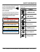
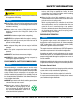
Safety Information Do not operate or service the equipment before reading the entire manual. Safety precautions should be followed at all times when operating this equipment. Failure to read and understand the safety messages and operating instructions could result in injury to yourself and others. Potential hazards associated with the operation of this equipment will be referenced with hazard symbols which may appear throughout this manual in conjunction with safety messages.
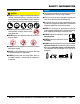
Safety Information geneRaL saFeTy CauTiOn neVeR operate this equipment without proper protective clothing, shatterproof glasses, respiratory protection, hearing protection, steel-toed boots and other protective devices required by the job or city and state regulations. neVeR operate this equipment when not feeling well due to fatigue, illness or when under medication. neVeR operate this equipment under the influence of drugs or alcohol.
Safety Information COMpaCTOR saFeTy dangeR neVeR operate the equipment in an explosive atmosphere or near combustible materials. An explosion or fire could result causing severe bodily harm or even death. WaRning neVeR disconnect any emergency or safety devices. These devices are intended for operator safety. Disconnection of these devices can cause severe injury, bodily harm or even death. Disconnection of any of these devices will void all warranties.
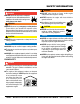
Safety Information FueL saFeTy baTTeRy saFeTy (eLeCTRiC sTaRT OnLy) dangeR dangeR dO nOT add fuel to equipment if it is placed inside truck bed with plastic liner. Possibility exists of explosion or fire due to static electricity. FUEL dO nOT drop the battery. There is a possibility that the battery will explode. dO nOT expose the battery to open flames, sparks, cigarettes, etc. The battery contains combustible gases and liquids.
Safety Information TRanspORTing saFeTy CauTiOn NEVER allow any person or animal to stand underneath the equipment while lifting. NOTICE When the life cycle of this equipment is over, remove battery and bring to appropriate facility for lead reclamation. Use safety precautions when handling batteries that contain sulfuric acid. When the life cycle of this equipment is over, it is recommended that the trowel frame and all other metal parts be sent to a recycling center.
Specifications Table 1. MVC88VTH/VTHW One-Way Plate Compactor Specifications Centrifugal Force 3,372 lbs. (1,530 kg) Vibration Frequency 6,000 vpm (60 Hz) Traveling Speed 82 ft/min (25 m/min) Plate Size (L x W) 19.7 x 20.7 in (.500 x .525 mm) Max. Area of Compaction (no extensions) 8,100 sq. ft./hr (752 sq. m/hr) Operating Weight MVC88VTGH 207 lbs. (95 kg.) Operating Weight MVC88VTHW 229 lbs. (104 kg.) Water Tank Capacity 13.7 qt (13.0 liters) Anti-Vibration Handle Yes Lubricating Oil in Vibration Case 6.
dimensions A D B C E Figure 1. Dimensions Table 3. Dimensions REF. DES IN. (MM) A 24.5 (622) B 22.5 (571) C 43.5 (1,105) D 36.0 (914) E 19.7 (500) page 12 — MVC88VTH/VTHW PLATE COMPACTOR • operation and parts manual — rev.
general information Definition of Plate Compactor Frequency/Speed The Mikasa MVC88VTH/VTHW is a walk behind, plate compactor designed for the compaction of sand, mixed soils and asphalt. This plate compactor is a powerful compacting tool capable of applying a tremendous force in consecutive high frequency vibrations to a soil surface. Its applications include compacting for road, embankments and reservoirs as well as backfilling for gas pipelines, water pipelines and cable installation work.
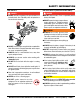
compactor components 1 MVC88VTHW MVC88VTH 2 9 3 4 8 10 5 OFF 6 ON 7 11 Figure 2. Plate Compactor Components Figure 2 shows the location of the basic controls and components of the MVC88VTH/VTHW Plate Compactor. The function of each control is described below: 1. Handle Bar – When operating the compactor use this handle bar to manuever the compactor. 2. Lifting Bale – When lifting of the compactor is required either by forklift, crane etc., tie rope or chain around this lifting point. 3.
compactor components 1 9 8 2 7 12 6 5 11 4 10 3 Figure 3. Engine Controls and Components INITIAL SERVICING The engine (Figure 3) must be checked for proper lubrication and filled with fuel prior to operation. Refer to the manufacturer's engine manual for instructions and details of operation and servicing. 1. Fuel Filler Cap – Remove this cap to add unleaded gasoline to the fuel tank. Make sure cap is tightened securely. DO NOT over fill.
inspection Before Starting DANGER 1. Read all safety instructions at the beginning of manual. EXPLOSIVE FUEL! 2. Clean the compactor, removing dirt and dust, particularly the engine cooling air inlet, carburetor and air cleaner. Motor fuels are highly flammable and can be dangerous if mishandled. DO NOT smoke while refueling. DO NOT attempt to refuel the compactor if the engine is hot! or running. 3. Check the air filter for dirt and dust.
inspection V-belt V-Belt Tension V-Belt Cover Removal The V-belt tension is proper if the V-belt bends 10 to 15 mm (Figure 10) when depressed with finger at midway between the clutch and vibrator pulleys. To inspect the V-belt, remove the three bolts that secure the belt cover to the frame as shown in Figure 8. REMOVE VIBRATOR CORRECT V-BELT TENSION 10-15 MM WHEN DEPRESSED AS SHOWN. CLUTCH PULLEY REMOVE V-BELT V-BELT asa ik M VIBRATOR PULLEY V-BELT COVER Figure 8.
startup CAUTION DO NOT attempt to operate the compactor until the Safety, General Information and Inspection sections of this manual have been read and thoroughly understood. 3. Place the choke lever (Figure 14) in the “CLOSED” position if starting a cold engine. CHOKE LEVER This section is intended to assist the operator with the initial start-up of the compactor. It is extremely important that this section be read carefully before attempting to use the compactor in the field. Starting the Engine 1.
startup 9. If the sprinkling of water is required, place water valve in the ON position. OFF ON Figure 16. Starter Grip NOTICE Figure 18. Water Valve (ON) 10. To begin compacting, place the throttle lever (Figure 19) in the “RUN” position. DO NOT pull the starter rope all the way to the end DO NOT release the starter rope after pulling. Allow it to rewind as soon as possible. 6. When engine starts, release the starter grip and allow the rope to recoil. 7.
operation Operation CAUTION ALWAYS follow all safety rules referenced in the safety section of this manual before operating compactor. Keep work area clear of debris and other objects that could cause damage to the compactor or bodily injury. Stopping the Engine Normal Shutdown 1. Move the throttle lever to the idle position (Figure 20) and run the engine for three minutes at low speed. 1. Once the engine has started, move the engine throttle lever quickly to the run position. 2.
operation/maintenance maintenance General Cleanliness General maintenance practices are crucial to the performance and longevity of your compactor. This equipment requires routine cleaning, inspection and lubrication. Reference Table 5 and Table 6 for scheduled engine and compactor maintenance. Clean the compactor daily. Remove all dust and debris buildup (mud, clay etc.). If the compactor is steam-cleaned, ensure that lubrication is accomplished AFTER steam cleaning.
maintenance Inspection and Maintenance Service Tables To make sure your plate compactor is always in good working condition before using, carry out the maintenance inspection in accordance with Table 5 and Table 6. Engine Maintenance Perform engine maintance as listed in Table 5. Description (3) Engine Oil Air Cleaner All Nuts and Bolts Spark Plug Cooling Fins Spark Arrester Fuel Tank Fuel Filter Idle Speed Valve Clearance Fuel lines Operation Table 5.
maintenance Machine Inspection Engine Air Cleaner DANGER Perfom machine inspection as listed in Table 6. Table 6. Machine Inspection Interval Check Solution Machine Clean if necessary. Fuel Tank For Leaks Repair fuel leaks. Fuel System for Leaks Repair fuel leaks. Engine Oil Add oil if necessary. Vibrator Oil Add oil if necessary. Air Cleaner Element Clean/Replace Daily Before Starting Guard Frame Inspect/deformations Shock Absorber Replace if damaged.
maintenance 3. Clean foam element in warm, soapy water or nonflammable solvent. Rinse and dry thoroughly. Dip the element in clean engine oil and completely squeeze out the excess oil from the element before installing. 3. Thread spark plug into cylinder hole by hand to prevent cross-threading, then tighten securely. GAP .028 - .031 IN. (0.7- 0.8 MM.) NOTICE Operating the engine with loose or damaged air cleaner components could allow unfiltered air into the engine causing premature wear and failure.
maintenance spark arrester cleaning Clean the spark arrester every 6 months or 100 hours. 1. Remove the 4 mm screw (3) from the exhaust deflector, then remove the deflector. See (Figure 27). 4. Carefully remove carbon deposits from the spark arrester screen (Figure 28) with a wire brush. WIRE BRUSH 2. Remove the 5 mm screw (4) from the muffler protector, then remove the muffler protector. 3.
EXPLANATION OF CODE IN REMARKS COLUMN The following section explains the different symbols and remarks used in the Parts section of this manual. Use the help numbers found on the back page of the manual if there are any questions. NOTICE The contents and part numbers listed in the parts section are subject to change without notice. Multiquip does not guarantee the availability of the parts listed. saMpLe paRTs LisT nO. 1 2% 2% 3 4 paRT nO. paRT naMe qTy. ReMaRks 12345 BOLT .....................1 .....
Suggested Spare Parts mvc88vth/mvc88vtwh PLATE COMPACTOR with HONDA GX160UT2QMX2 GASOLINE engine 1 to 5 units Qty. P/N Description 3 ...........070100332.............V-BELT 5............0650140480...........SPARK PLUG 1............28462ZH8003........ROPE, RECOIL STARTER 5............17210ZE1517........ELEMENT, AIR CLEANER 1............17620Z4H020........CAP, FUEL TANK 1............17672Z4H000........FUEL FILTER, FUEL TANK 4............939010230.............
body assy. 45 53 51 52 43 A 57 42 60 44 63 54 62 45 43 59 61 41 37 38 39 35 36 38 39 34 32 31 33 56 55 31 32 (EG) 57 9 34 58 35 10 11 12 19 7 6 18-4 15 16 29 26 6 27 28 5 7 13 2 64 65 36 4 8 18-5 18-1 18-2 24 18-3 23 20 18 21 22 26 27 28 17 14 26 27 28 3 25 3 4 2 1 page 28 — MVC88VTH/VTHW PLATE COMPACTOR • operation and parts manual — rev.
body assy. NO. A 1 2 3 4 5 6 7 8 9 10 11 12 13 14 15 16 17 18 18-1 18-2 18-3 18-4 18-5 19 20 21 22 23 24 25 26 27 28 29 31 32 33 34 35 36 37 38 39 41% PART NO.
body assy. (CONTINUED) 45 53 51 52 43 A 57 42 60 44 63 54 62 45 43 59 61 41 37 38 39 35 36 38 39 34 32 31 33 56 55 31 32 (EG) 57 9 34 58 35 10 11 12 19 7 6 18-4 15 16 29 26 6 27 28 5 7 13 2 64 65 36 4 8 18-5 18-1 18-2 24 18-3 23 20 18 21 22 26 27 28 17 14 26 27 28 3 25 3 4 2 1 page 30 — MVC88VTH/VTHW PLATE COMPACTOR • operation and parts manual — rev.
body assy. (CONTINUED) NO. 42% 43% 44% 45% 51 52 53 54 55 56 57 58 59 60 61 62 63 64 65 PART NO.
vibrator assy. 9 6 11 10 7 3 13 8 12 14 16 15 10 11 9 4 5 1 2 4 page 32 — MVC88VTH/VTHW PLATE COMPACTOR • operation and parts manual — rev.
vibrator assy. NO. 1 2 3 4 5 6 7 8 9 10 11 12 13 14 15 16 PART NO. 953405270 953405260 416218390 040406211 416338909 416338919 416349930 060203030 050101000 014208020 030208200 416464470 951405240 952404250 0105091025 030210250 PART NAME PLUG 1/4X14 X13L PACKING 1/4" ECCENTRIC ROTATOR BEARING 6211 CASE COVER (R) CASE COVER (L) BELT COVER GUARD OIL SEAL O-RING BOLT 8X20 WASHER, LOCK M8 PULLEY, VIBRATOR ASSY. KEY 7X7X19 WASHER 11X40X4 BOLT 10X25 WASHER, LOCK M10 QTY.
transport wheel assy. 59 58 61 62 61 70 55 20 63 57 72 71 56 22 31 21 51 31 50 32 32 41 33 42 48 47 45 52 53 39 34 43 44 37 38 36 36 36 35 page 34 — MVC88VTH/VTHW PLATE COMPACTOR • operation and parts manual — rev.
transport wheel assy. NO. 20 21 22 31 32 33 34 35 36 37 38 39 41 42 43 44 45 47 48 50 51 52 53 55 56 57 58 59 61 62 63 70 71 72 PART NO.
sprinkler assy. 11 12 10 A 12 13 1 2 3 8 5 7 9 4 6 7 page 36 — MVC88VTH/VTHW PLATE COMPACTOR • operation and parts manual — rev.
sprinkler assy. NO. A 1 2 3 4 5 6 7 8 9 10% 11% 12% 13% PART NO. 416910110 033910050 953406390 954403241 416338930 416338940 416452750 001220825 0401450080 416452790 954300342 001241030 033910160 022910270 PART NAME QTY. REMARKS WATER TANK W/CAP.........................................1 ...............INCLUDES ITEMS W/% WASHER 14.5X30X1.
URETHANE plate assy. 1 2 3 6 4 7 5 page 38 — MVC88VTH/VTHW PLATE COMPACTOR • operation and parts manual — rev.
URETHANE plate assy. NO. 1 2 3 4 5 6 7 PART NO. 416352080 001221230 012012030 416352090 011208035 022710809 PADUPA88 PART NAME QTY. REMARKS HANGER, URETHANE PLATE 1 BOLT 12X30 2 WASHER, LOCK M12 2 PLATE, URETHANE PLATE 1 BOLT 8X35 4 NYLON NUT M8 4 PAD, URETHANE...............................................1................REPLACES 416342390 MVC88VTH/VTHW PLATE COMPACTOR • operation and parts manual — rev.
nameplate and Decals assy. B 1 19 18 3 14 4 16 11 20 A 21 15 C 2 17 A C B page 40 — MVC88VTH/VTHW PLATE COMPACTOR • operation and parts manual — rev.
nameplate and Decals assy. NO. 1 2 3 4 11 11 14 15 16 17 18 19 20 21 PART NO. 920218170 920900090 920101410 920105070 920217430 920217440 920210330 920208350 920203290 920203060 920206290 920201580 920214100 920212320 PART NAME QTY. REMARKS DECAL, POSITION 1 DECAL, SET/MVC/EXP, EU ..............................1................ SET ONLY DECAL, MIKASA MARK 120X60 1 DECAL, MIKASA MARK 125MM 1 PLATE, SERIAL NO./88VTH 1 PLATE, SERIAL NO./88VTHW 1 DECAL, EC NOISE REQ.
honda GX160UT2QMX2 engine — CYLINDER HEAD ASSY. 15 12 12 5 14 10 6 7 3 2 14 4 1 13 13 14 14 11 10 10 11 8 page 42 — MVC88VTH/VTHW PLATE COMPACTOR • operation and parts manual — rev.
honda GX160UT2QMX2 engine — CYLINDER HEAD ASSY. NO. 1% 2% 3 4$% 5 6 7 8 10 11 12 13 14 15 PART NO. 12204ZE1306 12205ZE1315 12210Z4M405 12216ZE5300 12251ZL0003 12310Z4M000 12391ZE1000 15721ZH8000 90013883000 90043ZE1020 90047ZE1000 9430110160 957010806000 0650140480 PART NAME QTY. REMARKS GUIDE, INLET VALVE (O.S.) 1 GUIDE, EXHAUST VALVE (O. S.).......................1................INCLUDES ITEMS W/$ HEAD COMP, CYLINDER...................................1................
honda GX160UT2QMX2 engine — CYL. barrel ASSY. 4 7 6 12 17 4 5 15 3 6 19 19 16 21 17 18 13 11 9 8 14 11 9 1 page 44 — MVC88VTH/VTHW PLATE COMPACTOR • operation and parts manual — rev.
honda GX160UT2QMX2 engine — CYL. barrel ASSY. NO. 1 3 4% 5% 6% 7 8 9 11 12 13$ 14$ 15 16 17 18 19 21 PART NO. 12000Z4M406 16510Z4M000 16511Z4M000 16512Z4M000 16513ZE1000 16531Z4M000 16541Z4M000 90131ZE1000 90601ZE1000 90602ZE1000 91001ZF1003 91201Z0T801 91353671004 9405010000 9410106800 9425108000 957010601200 35480Z0T003 PART NAME QTY. REMARKS BARREL, ASSY CYLINDER (OIL ALERT).........1................INCLUDES ITEMS W/$ GOVERNOR ASSY.............................................1................
honda GX160UT2QMX2 engine — Crankcase cover ASSY. 9 9 9 9 4 6 9 8 8 7 10 11 5 3 2 page 46 — MVC88VTH/VTHW PLATE COMPACTOR • operation and parts manual — rev.
honda GX160UT2QMX2 engine — Crankcase cover ASSY. NO. 2 3 4 5 6$ 7# 8 9 10# 11% PART NO. 11300Z4M640 11381ZH8801 15600Z0T810 15600Z0T820 15625Z0T800 91201Z0T801 9430108140 957010803200 961006205000 15625Z0T800 PART NAME QTY. REMARKS COVER, ASSY. CRANKCASE............................1................INCLUDES ITEMS W/# GASKET CRANKCASE 1 CAP ASSY. OIL FILLER .....................................1................INCLUDES ITEMS W/$ CAP ASSY. OIL FILLER......................................1................
honda GX160UT2QMX2 engine — Crankshaft ASSY. 8 1 page 48 — MVC88VTH/VTHW PLATE COMPACTOR • operation and parts manual — rev.
honda GX160UT2QMX2 engine — Crankshaft ASSY. NO. 1 8 PART NO. 13310Z4M800 90745ZE1600 PART NAME CRANK SHAFT COMPLETE KEY 4.78X4.78X38 QTY. 1 1 REMARKS MVC88VTH/VTHW PLATE COMPACTOR • operation and parts manual — rev.
honda GX160UT2QMX2 engine — PISTON ASSY. 4 5 1 6 2 5 3 6 page 50 — MVC88VTH/VTHW PLATE COMPACTOR • operation and parts manual — rev.
honda GX160UT2QMX2 engine — PISTON ASSY. NO. 1 2 3 4 5$ 6 PART NO. 13010Z4M801 13101Z4M800 13111Z4M000 13200Z4M000 90001Z4M000 90551ZE1000 PART NAME QTY. REMARKS RING SET, PISTON (STD) 1 PISTON (STD) 1 PIN, PISTON 1 ROD AY, CONNECTING.....................................2................INCLUDES ITEMS W$ BOLT, CONNECTING ROD 6X34.5 2 CLIP, PISTON PIN 18MM 2 MVC88VTH/VTHW PLATE COMPACTOR • operation and parts manual — rev.
honda GX160UT2QMX2 engine — CAMSHAFT ASSY. 12 2 9 10 7 8 4 4 11 15 10 3 1 5 16 6 3 15 16 6 5 14 page 52 — MVC88VTH/VTHW PLATE COMPACTOR • operation and parts manual — rev.
honda GX160UT2QMX2 engine — CAMSHAFT ASSY. NO. 1 2 3 4 5 6 7$ 8 9 10 11 12 14 15 16 PART NO. 12209Z4M801 14100Z4M000 14410Z4M000 14431ZE1000 14441ZE1010 14451ZE1013 14568ZE1000 14711Z4M000 14721Z4M000 14751ZF1000 14771ZE1000 14773ZE1000 14791Z4M000 90012ZE0010 90206ZE1000 PART NAME QTY. REMARKS SEAL, VALVE STEM 1 CAMSHAFT ASSY..............................................1................
honda GX160UT2QMX2 engine — RECOIL STARTER ASSY. 1 12 5 9 7 4 3 8 6 2 16 15 9 4 11 13 page 54 — MVC88VTH/VTHW PLATE COMPACTOR • operation and parts manual — rev.
honda GX160UT2QMX2 engine — RECOIL STARTER ASSY. NO. 1 2$ 3$ 4$ 5$ 6$ 7$ 8$ 9$ 11$ 12$ 13 15$ 16$ PART NO. 28400Z4M305ZD 28410Z4M003ZD 28421Z0T003 28422ZH8801 28431ZH8801 28433ZH8801 28441ZH8801 28442ZH8003 28443ZH8801 28462ZH8003 90003ZH8801 90008ZE2003 28461Z4M305 28463Z4M003 PART NAME QTY. REMARKS STARTER ASSY., RECOIL.................................1................
honda GX160UT2QMX2 engine — FAN COVER ASSY. 10 18 17 4 12 16 8 15 15 15 15 1 page 56 — MVC88VTH/VTHW PLATE COMPACTOR • operation and parts manual — rev.
honda GX160UT2QMX2 engine — FAN COVER ASSY. NO. 1 4 8 10 12 15 16 17 18 PART NO. 19610Z4M000ZB 19611Z4M810 19630Z4M000 34150ZH7013 35120Z0T851 90013883000 90022888010 90601ZH7013 957010600800 PART NAME COVER COMPLETE PLATE CP, SIDE (OIL ALERT) SHROUD COMPLETE ALERT, UNIT, OIL SWITCH AY, E/G STOP FLANGE BOLT 6X12 FLANGE BOLT 6X20 CLIP, HARNESS FLANGE BOLT 6X8 QTY. 1 1 1 1 1 6 1 1 1 REMARKS MVC88VTH/VTHW PLATE COMPACTOR • operation and parts manual — rev.
honda GX160UT2QMX2 engine — CARBURETOR ASSY. 15 18 25 30 1 21 22 20 14 26 1 23 11 43 17 10 6 1 13 24 12 29 9 2 16 3 1 4 8 1 1 7 page 58 — MVC88VTH/VTHW PLATE COMPACTOR • operation and parts manual — rev.
honda GX160UT2QMX2 engine — CARBURETOR ASSY. NO. 1#@+&^ 2# 3# 4# 6# 7#+ 8# 9# 10 11# 12# 13# 14 15 16# 17 18 20# 21# 22# 23# 24# 25# 26% 29# 30# 43# PART NO. 16010ZE1812 16011ZE0005 16013Z0SB01 16015Z4M911 16016ZH7W01 16024Z5T901 16028Z5T901 16044Z4M911 16100Z4M911 16124ZE0005 16166Z4M911 16173001004 16211Z4M000 16212ZH8800 16220ZE1020 16221ZH8801 16610ZE1000 16953ZE1812 16954ZE1812 16956ZE1811 16957ZE1812 16967ZE0811 93500030060H 9430520122 99101ZH80700 99204ZE00350 16959Z5T901 PART NAME QTY.
honda GX160UT2QMX2 engine — AIR CLEANER ASSY. 13 4 2 1 12 10 5 3 8 9 6 7 7 11 11 page 60 — MVC88VTH/VTHW PLATE COMPACTOR • operation and parts manual — rev.
honda GX160UT2QMX2 engine — AIR CLEANER ASSY. NO. 1 2 3# 4 5# 6 7% 8% 9 10 11 12 13 PART NO. 16271ZE1000 17210ZE1517 17218ZE1507 17231Z4M010 17232891000 17235Z4M830 17238ZE7010 17239ZE1000 17410Z4M000 90325044000 9405006000 957010602000 90300Z1V000 PART NAME QTY. REMARKS PACKING, ELBOW 1 CLEANER ELEMENT.........................................1................
honda GX160UT2QMX2 engine — MUFFLER ASSY. 14 14 3 6 12 11 14 12 14 15 21 7 13 19 9 page 62 — MVC88VTH/VTHW PLATE COMPACTOR • operation and parts manual — rev.
honda GX160UT2QMX2 engine — MUFFLER ASSY. NO. 3 6 7 9 11 12 13 14 15 19 21 PART NO. 18320Z4M000 18340ZE1010 18355ZE1000 18381Z0T801 18522ZE1000 90002Z0T800 90016ZE1000 90050ZE1000 90055ZE1000 94001080000S 18310Z4M810 PART NAME PROTECTOR CP, MUFFLER (STD) DEFLECTOR CP ARRESTER, SPARK GASKET, MUFFLER GUIDE, MUFFLER SCREW, TAPPING, 4X8 FLANGE BOLT 6X13 TAPPING SCREW 5X8 TAPPING SCREW 4X6 NUT 8MM MUFFLER COMPLETE QTY.
honda GX160UT2QMX2 engine — FUEL tANK ASSY. 15 16 17 16 17 13 5 14 7 12 8 2 10 9 12 1 page 64 — MVC88VTH/VTHW PLATE COMPACTOR • operation and parts manual — rev.
honda GX160UT2QMX2 engine — FUEL tANK ASSY. NO. 1 2 5% 7 8 9 10 12 13 14 15 16 17 PART NO. 16854ZH8000 16955ZE1010 17631Z0T801 90004ZH7003 91353671004 9405006000 91424Z4M003 950024080008 17620Z4H020 17672Z4H000 17510Z4M000ZB 90503898000 91302Z4M003 PART NAME QTY. REMARKS RUBBER, SUPPORT (107MM) 1 JOINT, FUEL TANK 1 PACKING, FUEL FILLER CAP 1 FLANGE BOLT 6X29 1 O-RING 14MM 1 FLANGE NUT 6MM 2 TUBE, FUEL 4.5X145 1 CLAMP, TUBE (D8) 2 CAP COMP. , FUEL FILLER ..............................1................
honda GX160UT2QMX2 engine — FLYWHEEL ASSY. 5 2 1 9 4 page 66 — MVC88VTH/VTHW PLATE COMPACTOR • operation and parts manual — rev.
honda GX160UT2QMX2 engine — FLYWHEEL ASSY. NO. 1 2 4 5 9 PART NO. 13331357000 19511ZE1000 28451ZH8801 31110Z4M000 90201Z0T800 PART NAME WOODRUFF KEY 25X18 COOLING FAN STARTER PULLEY FLYWHEEL COMPLETE NUT, SPECIAL 14MM QTY. 1 1 1 1 1 REMARKS MVC88VTH/VTHW PLATE COMPACTOR • operation and parts manual — rev.
honda GX160UT2QMX2 engine — IGNITION COIL ASSY. 2 9 1 12 12 page 68 — MVC88VTH/VTHW PLATE COMPACTOR • operation and parts manual — rev.
honda GX160UT2QMX2 engine — IGNITION COIL ASSY. NO. 1 2 9 12 PART NO. 30500Z0T802 30700Z0T811 36101ZE1010 90121952000 PART NAME COIL ASSY, IGNITION CAP ASSY, NOISE SUPPRESSOR CORD, STOP SWITCH 370MM FLANGE BOLT 6X25 QTY. 1 1 1 2 REMARKS MVC88VTH/VTHW PLATE COMPACTOR • operation and parts manual — rev.
honda GX160UT2QMX2 engine — CONTROL ASSY. 30 22 3 5 8 9 24 18 13 26 12 19 25 11 21 15 27 21 7 14 28 17 16 page 70 — MVC88VTH/VTHW PLATE COMPACTOR • operation and parts manual — rev.
honda GX160UT2QMX2 engine — CONTROL ASSY. NO. PART NO. PART NAME QTY. REMARKS 3 16500Z4M306 CONTROL ASSY................................................1................
honda GX160UT2QMX2 engine — DECALS 13 12 4 5 3 14 15 16 17 18 19 page 72 — MVC88VTH/VTHW PLATE COMPACTOR • operation and parts manual — rev.
honda GX160UT2QMX2 engine — DECALS NO. PART NO. PART NAME 3 87521Z4M000 EMBLEM (GX160) 4 87528Z4M000 MARK, CHOKE 5 87532ZH7000 MARK, THROTTLE INDICATION 12 87516Z4H010 MARK, OP CAUTION (ENGLISH) 13 87539Z4M000 MARK, EX. CAUTION (ENGLISH) 14 87516Z4H801 MARK, OP CAUTION (FR) 15 87519Z4H000 MARK, OP CAUTION 16 87539Z4M800 MARK. EX. CAUTION (PICTOGRAP) 17 87539Z4M810 MARK, EX. CAUTION (FR) 18 89216Z0T800 WRENCH, SPARK PLUG 19 89219805000 HANDLE, BOX WRENCH QTY.
Terms and Conditions of Sale — Parts payMenT TeRMs 5. Parts must be in new and resalable condition, in the original Multiquip package (if any), and with Multiquip part numbers clearly marked. 6. The following items are not returnable: Multiquip reserves the right to quote and sell direct to Government agencies, and to Original Equipment Manufacturer accounts who use our products as integral parts of their own products. a. speCiaL eXpediTing seRViCe Terms of payment for parts are net 30 days.
notes MVC88VTH/VTHW PLATE COMPACTOR • operation and parts manual — rev.
Operation and Parts Manual HERE’S HOW TO GET HELP PLEASE HAVE THE MODEL AND SERIAL NUMBER ON-HAND WHEN CALLING United StateS Multiquip Corporate Office 18910 Wilmington Ave. Carson, CA 90746 Contact: mq@multiquip.com MQ Parts Department Tel.