
Owner manual


PAGE 14 —DM15A9C/CDM2CSA — OPERATION AND PARTS MANUAL — REV. #1 (11/09/05)
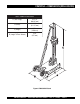
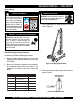
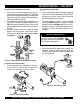
DM15A9C/CDM2CSA— DRILL RIG COMPONENTS
1. Leveling Screws – Use these screws (4) to level the
the drill rig.
2. Base – Supports the column rack and associated
components.
3. Wheels – 2 rear wheels have been provided for ease
of maneuverability. To move the drill rig grab hold of the
handle on the cradle assembly and tilt the unit slightly,
then pull or push.
4. Angle Rod – This is an adjustable rod. To shorten or
lengthen, squeeze and hold the rod release trigger. Set
angle rod to desired position, release trigger.
5. Adjustment Rod Cover Lock – This cover must be
secured to the column mast at all times when the unit
is in use. NEVER! use the drill rig with this cover
removed. The possibility exists of the column falling.
6. Cradle Assembly – This unit is responsible for the
raising and lowering of the core drill and is placed onto
the colum rack. There is a tensioner knob located on
the side of the cradle that determines the ease at which
the cradle will move up and down along the rack.
Adjust the tension so that the cradle moves smoothly
and freely. Before placing core drill onto cradle, always
make sure the tension knob is securely tightened. This
will prevent the core drill from falling.
7. Cradle Raise/Lower Handle – Use thishandle to raise
or lower the core drill.
8. Vacuum Hose Fitting – Connect the output end of the
vacuum pump hose to this fitting.
Figure 3. CDM2CSA Drill Rig Components
Figure 3 illustrates the basic componets of the MQ CDM2CSA
Drill Rig. Shown below is breif explanation of each componet.