OPERATION AND PARTS MANUAL SERIES MODEL MVC77 ONE-WAY PLATE COMPACTOR (HONDA GX160K1QX2 GASOLINE ENGINE) Revision #4 (01/14/11) To find the latest revision of this publication, visit our website at: www.multiquip.com THIS MANUAL MUST ACCOMPANY THE EQUIPMENT AT ALL TIMES.
PROPOSITION 65 WARNING l PAGE 2 — MVC77 PLATE COMPACTOR — OPERATION AND PARTS MANUAL — REV.
NOTES MVC77 PLATE COMPACTOR — OPERATION AND PARTS MANUAL — REV.
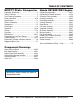
TABLE OF CONTENTS MVC77 Plate Compactor Honda GX160K1QX2 Engine Proposition 65 Warning ............................................. 2 Table Of Contents ..................................................... 4 Parts Ordering Procedures ....................................... 5 Safety Information ................................................ 6-10 Specifications .......................................................... 11 General Information ................................................
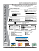
www.multiquip.com PARTS ORDERING PROCEDURES Ordering parts has never been easier! Choose from three easy options: Order via Internet (Dealers Only): Best Deal! Effective: January 1st, 2006 If you have an MQ Account, to obtain a Username and Password, E-mail us at: parts@multiquip. com. Order parts on-line using Multiquip’s SmartEquip website! ■ View Parts Diagrams ■ Order Parts ■ Print Specification Information To obtain an MQ Account, contact your District Sales Manager for more information.
SAFETY INFORMATION Do not operate or service the equipment before reading the entire manual. Safety precautions should be followed at all times when operating this equipment. Failure to read and understand the safety messages and operating instructions could result in injury to yourself and others. Potential hazards associated with the operation of this equipment will be referenced with hazard symbols which may appear throughout this manual in conjunction with safety messages.
SAFETY INFORMATION GENERAL SAFETY CAUTION NEVER operate this equipment without proper protective clothing, shatterproof glasses, respiratory protection, hearing protection, steel-toed boots and other protective devices required by the job or city and state regulations. NEVER operate this equipment when not feeling well due to fatigue, illness or when under medication. NEVER operate this equipment under the influence of drugs or alcohol.
SAFETY INFORMATION COMPACTOR SAFETY DANGER NEVER operate the equipment in an explosive atmosphere or near combustible materials. An explosion or fire could result causing severe bodily harm or even death. WARNING NEVER disconnect any emergency or safety devices. These devices are intended for operator safety. Disconnection of these devices can cause severe injury, bodily harm or even death. Disconnection of any of these devices will void all warranties.
SAFETY INFORMATION FUEL SAFETY BATTERY SAFETY (ELECTRIC START ONLY) DANGER DANGER DO NOT add fuel to equipment if it is placed inside truck bed with plastic liner. Possibility exists of explosion or fire due to static electricity. FUEL DO NOT drop the battery. There is a possibility that the battery will explode. DO NOT expose the battery to open flames, sparks, cigarettes, etc. The battery contains combustible gases and liquids.
SAFETY INFORMATION TRANSPORTING SAFETY CAUTION NEVER allow any person or animal to stand underneath the equipment while lifting. NOTICE Before lifting, make sure that the equipment parts (hook and vibration insulator) are not damaged and screws are not loose or missing. Always make sure crane or lifitng device has been properly secured to the lifting bail (hook) of the equipment. ALWAYS shutdown engine before transporting. NEVER lift the equipment while the engine is running.
SPECIFICATIONS TABLE 1. COMPACTOR SPECIFICATIONS Model MVC-77, S, H and SH Centrifugal Force 3,350 lbs. (1520 kg) Number of Vibrations 5,800 vibrations/min Traveling Speed 82 meters/min (82 ft./min) Plate Size (LxW) .49 x .57 cm (17 x 22 in.) 166 lbs. (75.0 kg.) 195 lbs. ( 88.4 kg.) Operating Weight Operating Weight (Water Tank) Water Tank Capacity 13.7 qt. 6970 sq. ft./hr. Max. Area Of Compaction TABLE 2.
GENERAL INFORMATION Definition of Plate Compactor Frequency/Speed The Mikasa MVC77 Series is a walk behind, plate compactor designed for the compaction of sand, mixed soils and asphalt. This plate compactor is a powerful compacting tool capable of applying a tremendous force in consecutive high frequency vibrations to a soil surface. Its applications include compacting for road, embankments and reservoirs as well as backfilling for gas pipelines, water pipelines and cable installation work.
COMPONENTS 4 3 2 1 5 11 WATER TA NK 9 10 6 sa ka Mi Mikas a 8 7 Figure 1. MVC77 Series Plate Compactor Components Figures 1 and 2 shows the location of the components and general maintenance parts. The function of each component is described below: 6. Belt Cover – Remove this cover to gain acess to the Vbelts. NEVER run the compactor without the V-belt cover.
BASIC ENGINE Figure 2. Engine Controls & Components INITIAL SERVICING The engine (Figure 2) must be checked for proper lubrication and filled with fuel prior to operation. Refer to the manufacturers Engine manual for instructions & details of operation and servicing. 1. 6. Choke Lever – Used in the starting of a cold engine, or in cold weather conditions. The choke enriches the fuel mixture. 7. Air Cleaner – Prevents dirt and other debris from entering the fuel system.
INSPECTION Before Starting NOTICE 1. Read safety instructions at the beginning of manual. 2. Clean the compactor, removing dirt and dust. Particularly, the bottom of the plate, engine cooling air inlet, carburetor and air cleaner. 3. Check the air filter for dirt and dust. If the air filter is dirty, blow through the air filter cartridge from the inside, moving a jet of dry compressed air up and down until all dust is removed. Otherwise replace air filter with a new one. 4.
INSPECTION V-Belt Check CAUTION NEVER attempt to check the V-belt with the engine running. Severe injury can occur of your hand (Figure 6) gets caught between the V-belt and the clutch. Always use safety gloves. 2. The V-belt tension is proper if the V-belt bends 10 to 15 mm (Figure 8) when depressed with finger at midway between the clutch and vibration pulley shafts. CLUTCH PULLEY Figure 8. V-Belt Tension 3.
STARTUP CAUTION DO NOT attempt to run the compactor until the Safety D Information and Startup sections have been read. NOTICE The CLOSED position of the choke lever enriches the fuel mixture for starting a COLD engine. The OPEN position provides the correct fuel mixture for normal operation after starting, and for restarting a warm engine. 1. Place the fuel valve lever (Figure 9) in the "ON" position. 4. Place the throttle lever (Figure 12) halfway between fast and slow. Figure 9. Fuel Valve Lever 2.
STARTUP 6. If the engine has started, slowly return the choke lever (Figure 11) to the CLOSED position. If the engine has not started repeat steps 1 through 5. 7. Before the compactor is put into operation run the engine for 3-5 minutes. 8. Check for abnormal engine noises or fuel leaks. Stopping the Engine CAUTION NEVER stop the engine suddenly while working at high speeds. 1. Place the throttle lever (Figure 12) in slow position, and listen for the engine speed to decrease. 2.
OPERATION Operation CAUTION Make sure to follow all safety rules referenced in the safety section of this manual before operating compactor. Keep work area clear of debris and other objects that could cause damage to the compactor or bodily injury. 1. Once the engine has started, move the engine throttle lever quickly to the fast position. 2. With the throttle lever in the fast position, the engine speed should be around 2,300 RPM, therefore engaging the centrifugal clutch.
MAINTENANCE CAUTION Inspection and other services should always be carried out on hard and level ground with the engine shutdown. Inspection and Maintenance Service Tables. CAUTION These inspection intervals are for operation under normal conditions. Adjust your inspection intervals based on the number hours plate compactor is in use, and particular working conditions. 1.
MAINTENANCE CAUTION NEVER attempt to check the V-belt with the engine running. Severe injury can occur if your hand (Figure 6) gets caught between the V-belt and the clutch. Always use safety gloves. Checking and Replacing the V-Belt and Clutch 1. After 200 hours of operation, remove the upper belt cover to check the V-belt tension. Tension is proper if the belt bends about 10 mm when depressed strongly with finger between shafts.
PREPARATION FOR LONG-TERM STORAGE Pump Storage For storage of the pump for over 30 days, the following is required: Drain the fuel tank completely. Run the engine until the fuel in the injection system is completely consumed. Completely drain the oil from the engine crankcase and follow procedures described in the HONDA engine Owner's Manual for engine storage. Completely drain the compactor's hydraulic oil from the vibrating case.
TROUBLESHOOTING TABLE 7. ENGINE TROUBLESHOOTING SYMPTON Difficult to star t, "fuel is available, but no SPARK at spark plug". POSSIBLE CAUSE Spark plug bridging? Check gap, insulation or replace spark plug. Carbon deposit on spark plug? Clean or replace spark plug. Shor t circuit due to deficient spark plug insulation? Check spark plug insulation, replace if worn. Improper spark plug gap? Set to proper gap. ON/OFF switch is shor ted? Check switch wiring, replace switch.
TROUBLESHOOTING TABLE 7. ENGINE TROUBLESHOOTING (CONTINUED) SYMPTON "Weak in power" compression is proper and does not misfire. POSSIBLE CAUSE SOLUTION Air cleaner not clean? Clean or replace air cleaner Improper level in carburetor? Check float adjustment, re-build carbureator. Defective Spark plug? Clean or replace spark plug. Defective Spark plug? "Weak in power" compression is proper but misfires. Engine overheats. Rotational speed fluctuates. Recoil star ter malfunction.
TROUBLESHOOTING TABLE 8. PLATE COMPACTOR TROUBLESHOOTING SYMPTON POSSIBLE CAUSE SOLUTION Engine speed too low? Set engine speed to correct RPM. Clutch slips? Check or replace clutch. Travel speed too low, and vibration is V-belt slips? weak. Excessive oil in vibrator? Adjust or replace V-belt. Drain excess oil and fill to proper level. Malfunction in vibrator housing? Check eccentric, gears and counter weights.
EXPLANATION OF CODES IN REMARKS COLUMN The following section explains the different symbols and remarks used in the Parts section of this manual. Use the help numbers found on the back page of the manual if there are any questions. NOTICE The contents and part numbers listed in the parts section are subject to change without notice. Multiquip does not guarantee the availability of the parts listed. SAMPLE PARTS LIST NO. 1 2% 2% 3 4 PART NO. PART NAME QTY. REMARKS 12345 BOLT......................1 .....
SUGGESTED SPARE PARTS MVC77 Series1 TO 5 UNITS WITH HONDA GX160K1QX2 ENGINE 1 to 3 Units Qty. P/N Description 3 ............ 070503350 ............ V-BELT 1 ............ 060403060 ............ OIL SEAL, VIBRATING 2 ............ 050101000 ............ O-RING (FOR HANDLE) 3 ............ 9807956841 .......... SPARK PLUG (HONDA) 1 ............ 28462ZH8003 ....... ROPE, RECOIL STARTER (HONDA) 1 ............ 36100ZE1015 ....... SWITCH ASSY, ENGINE STOP (HONDA) 3 ............ 17210ZE1505 .......
NAMEPLATE AND DECALS l PAGE 28 — MVC77 PLATE COMPACTOR — OPERATION AND PARTS MANUAL — REV.
NAMEPLATE AND DECALS NO PART NO PART NAME 1 2 3 4 5 6 7 8 920203290 920203060 920201580 920106460 920201950 DECAL: DECAL: DECAL: DECAL: DECAL: PLATE: DECAL: DECAL: 13118 920203330 CAUTION CAUTION (START ENG/VIBR) MQ LOGO MIKISA LOGO (NAME) MOTOR OIL SERIAL NO./MVC-MQ POWDER COATED EAR PROTECTION LABEL QTY. 1 1 2 1 1 1 1 1 REMARKS DSC01 NPA-306 NPA-158 NPA-507 NPA-195 CONTACT MQ SERVICE DEPT. W/MODEL & S/N NPA-333 MVC77 PLATE COMPACTOR — OPERATION AND PARTS MANUAL — REV.
MAIN BODY ASSY. l PAGE 30 — MVC77 PLATE COMPACTOR — OPERATION AND PARTS MANUAL — REV.
MAIN BODY ASSY.
ENGINE PULLEY/CLUTCH ASSY. ENGINE PULLEY/CLUTCH ASSY. l PAGE 32 — MVC77 PLATE COMPACTOR — OPERATION AND PARTS MANUAL — REV.
ENGINE PULLEY/CLUTCH ASSY. ENGINE PULLEY/CLUTCH ASSY. NO PART NO 10 10 10 19 19 20 21 22 23 23 24 25 29 30 50 51 52 53 54 55 56 57 58 59 76 78 79 80 81 82 EH172YD4020 ENGINE ASSY. (ROBIN) ............................ 1 ............. REPLACES 911202046 ENGINE ASSY. (HONDA) .......................... 1 ............. GX140Q1B5 NO LONGER AVAILABLE GX160K1QX2 ENGINE ASSY. (HONDA) .......................... 1 ............. REPLACES 912216002 408420830 CLUTCH SPACER ..................................... 1 .....
VIBRATOR/PLATE MOUNTING ASSY. l PAGE 34 — MVC77 PLATE COMPACTOR — OPERATION AND PARTS MANUAL — REV.
VIBRATOR/PLATE MOUNTING ASSY. NO PART NO PART NAME 1 46 47 48 30 408105330 012212035 030212300 031112230 408910010 VIBRATING PLATE 1 BOLT 12X35 T ......................................... 9 ................ REPLACES 001221235 SPRING WASHER M12 9 PLAIN WASHER M12 9 VIBRATOR ASSY. ................................... 1 ................ SEE PAGES 36 AND 37 QTY. REMARKS MVC77 PLATE COMPACTOR — OPERATION AND PARTS MANUAL — REV.
VIBRATOR ASSY. l PAGE 36 — MVC77 PLATE COMPACTOR — OPERATION AND PARTS MANUAL — REV.
VIBRATOR ASSY. NO PART NO PART NAME 1 2 3 4 5 6 7 8 9 10 11 12 13 14 15 16 17 18 20 30 408010057 401301260 401301270 401010190 040406309 011208025 030208200 953400270 953405260 408420840 401010220 001221235 030212300 951010090 401010200 401010240 014212030 060203030 920101190 408910010 VIBRATING CASE/77,90 .......................... 1 .............. REPLACES 408010050 CASE COVER/A 1 CASE COVER/B 1 PACKING 2 BEARING 2 BOLT 8 X 25 T ......................................... 12 ..............
WATER TANK ASSY. l PAGE 38 — MVC77 PLATE COMPACTOR — OPERATION AND PARTS MANUAL — REV.
WATER TANK ASSY. NO PART NO 39 40 41 42 43 44 408106380 408316691 408424691 954403240 959403790 402010060 PART NAME QTY. REMARKS WATER TANK 1 CAP, WATER TANK (W/PK) .................... 1 ........ REPLACES 408316690 PACKING, 115D-2T 1 COCK PT 1/4, BH-1211 1 NUT PS-1/4 1 VINYL PIPE 9.5X14X450L ...................... 1 ....... REPLACES 408424840 MVC77 PLATE COMPACTOR — OPERATION AND PARTS MANUAL — REV.
HONDA GX160K1QX2 — CYLINDER ASSY. l PAGE 40 — MVC77 PLATE COMPACTOR — OPERATION AND PARTS MANUAL — REV.
HONDA GX160K1QX2 — CYLINDER ASSY. NO PART NO PART NAME 1 2 4 6 7 8 9 10 11 12 13 14 16 17 17 12210ZH8000 12204ZE01306 12205ZE1315 12216ZE5300 12251ZF1800 12310ZE1010 12391ZE1000 15721ZH8000 90013883000 90043ZE1020 90047ZE1000 9430110160 957230806000 9807956841 9807956854 HEAD COMP., CYLINDER GUIDE, INLET VALVE GUIDE, EXHAUST VALVE CLIP, VLAVE GUIDE GASKET, CYLINDER HEAD COVER COMP.
HONDA GX160K1QX2 — CYLINDER BARREL ASSY. l PAGE 42 — MVC77 PLATE COMPACTOR — OPERATION AND PARTS MANUAL — REV.
HONDA GX160K1QX2 — CYLINDER BARREL ASSY. NO PART NO PART NAME 2 4 8 9 11 12 13 14 15 18 19 21 12000ZH8010 16510ZE1000 16531ZE1000 16541ZE1000 90131ZE1000 90451ZE1000 90601ZE1000 90602ZE1000 91202883005 9410106800 9425108000 91001ZF1003 BARREL ASSY. CYLINDER ................. 1 ............INCLUDES ITEMS W/ GOVERNOR ASSY.
HONDA GX160K1QX2 — CRANKCASE COVER ASSY. l PAGE 44 — MVC77 PLATE COMPACTOR — OPERATION AND PARTS MANUAL — REV.
HONDA GX160K1QX2 — CRANKCASE COVER ASSY. NO PART NO PART NAME 1 4 5 6 8# 9% 13 14 16 17 11300ZZE1633 11381ZH8801 15600ZE1003 15600ZG4003 15625ZE1003 15625ZE1003 91202883005 9430108140 957010803200 961006205000 COVER ASSY. CRANKCASE ...... 1 ............ INCLUDES ITEMS W/ GASKET CRANKCASE 1 OIL GAUGE ASSY. ...................... 1 ............ INCLUDES ITEMS W/% OIL PLUG ASSY. ......................... 1 ............
HONDA GX160K1QX2 — CRANKSHAFT ASSY. l PAGE 46 — MVC77 PLATE COMPACTOR — OPERATION AND PARTS MANUAL — REV.
HONDA GX160K1QX2 — CRANKSHAFT ASSY. NO PART NO PART NAME 2 13 14 15 13310ZE1000 92101080250A 90473842000 90741883810 CRANKSHAFT COMP. BOLT WASHER 8MM KEY 5X5X33 QTY. REMARKS 1 1 1 1 MVC77 PLATE COMPACTOR — OPERATION AND PARTS MANUAL — REV.
HONDA GX160K1QX2 — PISTON ASSY. PISTON ASSY. l PAGE 48 — MVC77 PLATE COMPACTOR — OPERATION AND PARTS MANUAL — REV.
HONDA GX160K1QX2 — PISTON ASSY. PISTON ASSY. NO PART NO PART NAME 1 1 1 1 2 2 2 2 3 4 5# 6 13010ZH8941 13011ZH8941 13012ZH8941 13013ZH8941 13101ZH8000 13102ZH8000 13103ZH8000 13104ZH8000 13111ZE1000 13200ZE1010 90001ZE1000 90551ZE1000 RING SET, PISTON (STD) 1 RING SET, PISTON (0.25) 1 RING SET, PISTON (0.50) 1 RING SET, PISTON (0.75) 1 PISTON (STD) 1 PISTON (0.25) 1 PISTON (0.50) 1 PISTON (0.75) 1 PISTON PIN 1 CONNECTING ROD ASSY. ............ 1 ...................
HONDA GX160K1QX2 — CAMSHAFT ASSY. l PAGE 50 — MVC77 PLATE COMPACTOR — OPERATION AND PARTS MANUAL — REV.
HONDA GX160K1QX2 — CAMSHAFT ASSY. NO PART NO PART NAME 1 3 5 6 7 8# 9 10 11 12 13 14 15 16 17 14100ZE1812 14410ZE1010 14431ZE1000 14441ZE1010 14451ZE1013 14568ZE1000 14711ZF1000 14721ZF1000 14751ZF1000 14771ZE1000 14773ZE1000 14781ZE1000 14791ZE1010 90012ZE0010 90206ZE1000 CAMSHAFT ASSY. ...................... 1 ..........
HONDA GX160K1QX2 — RECOIL STARTER ASSY. l PAGE 52 — MVC77 PLATE COMPACTOR — OPERATION AND PARTS MANUAL — REV.
HONDA GX160K1QX2 — RECOIL STARTER ASSY. NO PART NO PART NAME 1 1 2# 3# 4# 5# 6# 7# 8# 9# 10# 12# 13 15 28400ZH8013ZA 28400ZH8013ZB 28410ZH8003ZA 28420ZH8013 28422ZH8013 28433ZH8003 28441ZH8003 28442ZH8003 28443ZH8003 28461ZH8003 28462ZH8003 90003ZH8003 957010600800 32901MA1000 RECOIL STARTER*NH1* (RED) ..... 1 ........ INCLUDES ITEMS W/# RECOIL STARTER*NH1* (BLACK) . 1 ........ INCLUDES ITEMS W/# CASE COMP.
HONDA GX160K1QX2 — FAN COVER ASSY. l PAGE 54 — MVC77 PLATE COMPACTOR — OPERATION AND PARTS MANUAL — REV.
HONDA GX160K1QX2 — FAN COVER ASSY. NO PART NO PART NAME 3 7 10 15 16 21 22 19610ZE1000ZA 19612ZH8000 19630ZH8000 36100ZE1015 36101ZE1010 90013883000 90022888010 FAN COVER COMP. SIDE PLATE (STD) SHROUD COMP. SWITCH ASSY. ENGINE STOP CORD, STOP SWITCH 370MM FLANGE BOLT 6X12 FLANGE BOLT 6X20 QTY. REMARKS 1 1 1 1 1 6 1 MVC77 PLATE COMPACTOR — OPERATION AND PARTS MANUAL — REV.
HONDA GX160K1QX2 — CARBURETOR ASSY. l PAGE 56 — MVC77 PLATE COMPACTOR — OPERATION AND PARTS MANUAL — REV.
HONDA GX160K1QX2 — CARBURETOR ASSY.
HONDA GX160K1QX2 — AIR CLEANER ASSY. l PAGE 58 — MVC77 PLATE COMPACTOR — OPERATION AND PARTS MANUAL — REV.
HONDA GX160K1QX2 — AIR CLEANER ASSY. NO PART NO PART NAME 1 2 3 4 5 6 7% 8% 9 12 13 14 15 16271ZE1000 17210ZE1822 17218ZE1821 17230ZE1820 17232891000 17235ZE1831 17238ZE7010 17239ZE1000 17410ZE1020 90325044000 90325044000 957010602000 9405006000 PACKING, ELBOW 1 CLEANER ELEMENT .................... 1 ...................... INCLUDES ITEMS W/ OUTER ELEMENT 1 COVER, AIR CLEANER 1 GROMET, AIR CLEANER 1 NOSE, SILENCER 1 COLLAR, AIR CLEANER 2 COLLAR (B), AIR CLEANER 1 ELBOW COMP., AIR CLEANER ... 1 .........
HONDA GX160K1QX2 — MUFFLER ASSY. l PAGE 60 — MVC77 PLATE COMPACTOR — OPERATION AND PARTS MANUAL — REV.
HONDA GX160K1QX2 — MUFFLER ASSY. NO PART NO PART NAME 2 3 5 7 9 10 11 12 13 14 18310ZF1000 19320ZF1H01 18325ZE1010 18340ZE1010 18381ZH8800 18522ZE1000 90050ZE1000 90055ZE1000 90002ZG0003 94001080000S MUFFLER COMP. MUFFLER PROCTOR (STD) PROCTECTOR, LOWER DEFLECTOR CP GASKET, MUFFLER GUIDE, MUFFLER TAPPING SCREW 5X8 TAPPING SCREW 4X6 TAPPING SCREW 4X8 NUT QTY. REMARKS 1 1 1 1 1 1 4 3 2 2 MVC77 PLATE COMPACTOR — OPERATION AND PARTS MANUAL — REV.
HONDA GX160K1QX2 — FUEL TANK ASSY. l PAGE 62 — MVC77 PLATE COMPACTOR — OPERATION AND PARTS MANUAL — REV.
HONDA GX160K1QX2 — FUEL TANK ASSY. NO PART NO PART NAME 10 17 20 21 23% 24 29 33 36 40 43 16854ZH8000 16955ZE1000 17510ZE1020ZA 17620ZH7023 17631ZH7003 17672ZE2W01 91353671004 9405006000 950014514040 9500202080 957010602500 RUBBER, SUPPORT (107MM) JOINT, FUEL TANK FUEL TANK COMP. FUEL TANK CAP CP ..................... PACKING FUEL FILTER O-RING 14MM FLANGE NUT 6MM FUEL TUBE 4.5X140 CLIP, TUBE FLANGE BOLT 6X25 QTY. REMARKS 1 1 1 1 ............................
HONDA GX160K1QX2 — COOLING FAN & FLYWHEEL ASSY. l PAGE 64 — MVC77 PLATE COMPACTOR — OPERATION AND PARTS MANUAL — REV.
HONDA GX160K1QX2 — COOLING FAN & FLYWHEEL ASSY. NO 1 5 6 10 11 PART NO 19511ZE1000 28451ZH8003 31100ZE1010 90201878003 13331357000 PART NAME COOLING FAN STARTER PULLEY FLYWHEEL COMP. SPECIAL NUT 14MM WOODRUFF KEY 25X18 QTY. 1 1 1 1 1 REMARKS MVC77 PLATE COMPACTOR — OPERATION AND PARTS MANUAL — REV.
HONDA GX160K1QX2 — IGNITION COIL ASSY. l PAGE 66 — MVC77 PLATE COMPACTOR — OPERATION AND PARTS MANUAL — REV.
HONDA GX160K1QX2 — IGNITION COIL ASSY. NO 1 2 14 PART NO 30500ZE1033 30600ZE1013 90121952000 PART NAME IGNITION COIL CP ASSY. SPARK PLUG CAP ASSY. FLANGE BOLT 6X25 QTY. 1 1 2 REMARKS MVC77 PLATE COMPACTOR — OPERATION AND PARTS MANUAL — REV.
HONDA GX160K1QX2 — CONTROL ASSY. l PAGE 68 — MVC77 PLATE COMPACTOR — OPERATION AND PARTS MANUAL — REV.
HONDA GX160K1QX2 — CONTROL ASSY. NO PART NO PART NAME 2 3 4 5 7 9 10 11 12 13 15 16 17 18 21 22 24 26 27 28 29 30 16551ZE0010 16555ZE1000 16561ZE1020 16562ZE1020 16500ZH8812 16571ZH8010 16574ZE1000 16575ZH8000 16576891000 16578ZE1000 16580ZH8812 16584883300 16592ZE1810 16594883010 90013883000 90015ZE5010 90605230000 93500040060H 93500050250H 93500050160A 90114SA0000 940500600 GOVERNOR ARM GOVERNOR ROD GOVERNOR SPRING SRRING, THROTTLE CONTROL ASSY.
TERMS AND CONDITIONS OF SALE — PARTS PAYMENT TERMS 5. Parts must be in new and resalable condition, in the original Multiquip package (if any), and with Multiquip part numbers clearly marked. 6. The following items are not returnable: Multiquip reserves the right to quote and sell direct to Government agencies, and to Original Equipment Manufacturer accounts who use our products as integral parts of their own products. a. SPECIAL EXPEDITING SERVICE Terms of payment for parts are net 30 days.
MVC77 PLATE COMPACTOR — OPERATION AND PARTS MANUAL — REV.
OPERATION AND PARTS MANUAL HERE’S HOW TO GET HELP PLEASE HAVE THE MODEL AND SERIAL NUMBER ON-HAND WHEN CALLING UNITED STATES Multiquip Corporate Office 18910 Wilmington Ave. Carson, CA 90746 Contact: mq@multiquip.com MQ Parts Department Tel.