
Owner manual


LS60TD AND LS600 — CONTROL BOX REPLACEMENT — REV. #1 (03/23/12) — PAGE 2
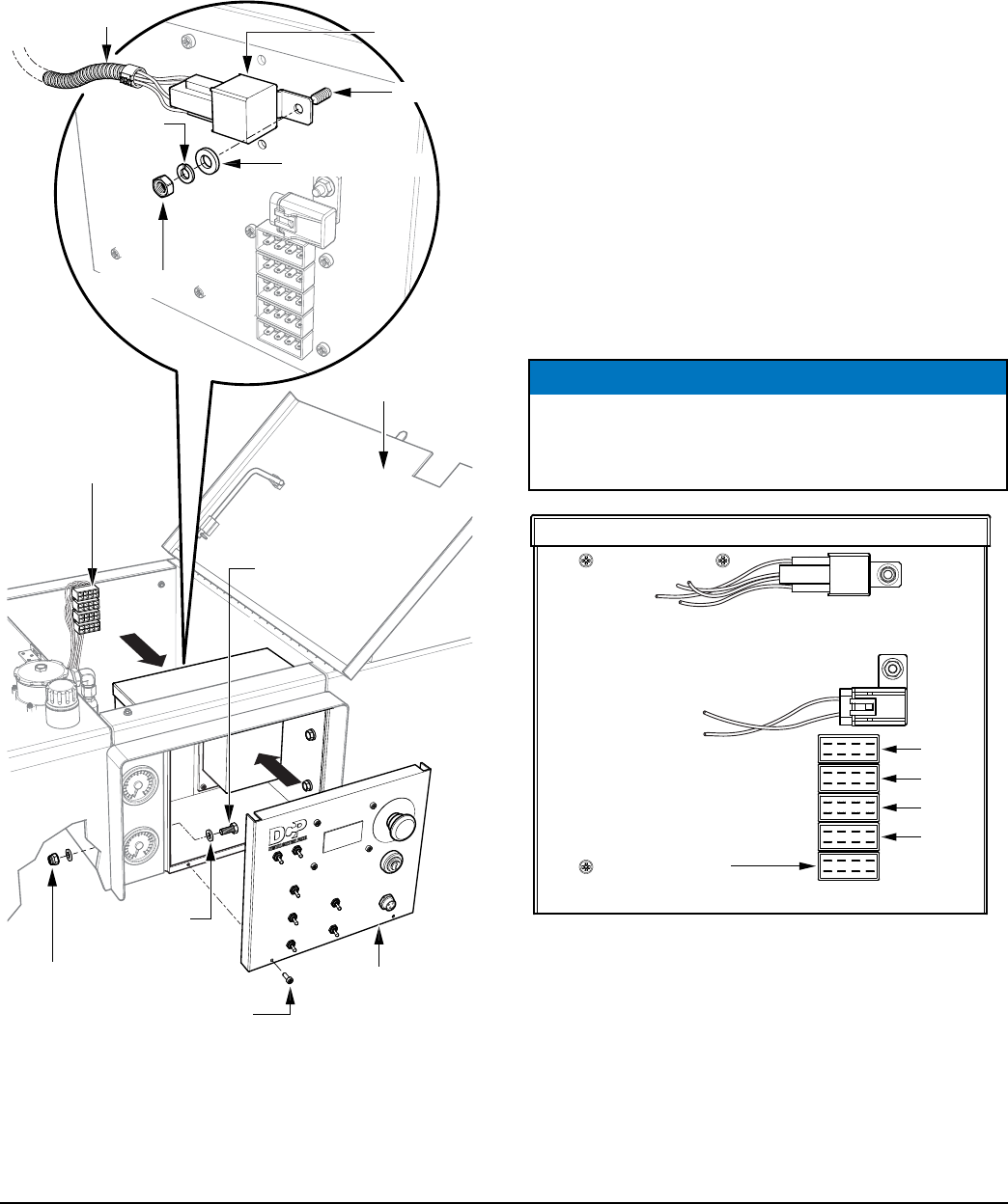
INSTALLATION
1. Install the replacement digital control box on the pump
using the existing hardware. See Figure 3.
Figure 3. Replacement Digital Box Installation
2. Attach the relay kit to the digital control box by securing
it to the stud shown in Figure 3, using the appropriate
hardware (user provided).
HATCH
NEW
CONTROL
PANEL
LOCK NUT (4)
SCREW (2)
FLAT
WASHER (8)
HARNESS
RELAY
HEX BOLT (4)
PLUGS
HEX NUT
LOCK
WASHER
FLAT WASHER
CONTROL BOX REAR VIEW
STUD
CONNECTIONS
Refer to Figure 5 for connections from the relay to the plugs .
1. Connect #86 purple 12 AWG wire from Relay K1 to
terminal #6 on Plug P1 using a spade connector.
2. Connect #85 black wire from Relay K1 to starter ground
point using a butt splice.
3. Connect #87 purple 10 AWG wire from Relay K1 to
terminal #4 on Plug P1 using a butt splice.
4. Cut wire from terminal #4 on Plug P4 flush to the plug.
Terminal will not be used.
5. Connect #30 red wire from Relay K1 to the other end
of the cut wire using a butt splice.
6. Reconnect the 4 plugs to the corresponding receptacles
on the new control box. See Figure 4 for location of
receptacles. Receptacle J5 will not be used.
Figure 4. Control Box Rear Receptacles
7. Install the fuse to the rear of the new control box.
8. After all connections are made, reconnect the battery.
Turn the control panel ignition switch to the ON position.
The control box panel should light. You will see and
hear the engine fuel solenoid energize.
9. Perform control box programming instructions.
NOTICE
Use extreme care when connecting the control box rear
receptacle plugs to make sure that correct orientation
is followed.
J1
Relay
Fuse
Receptacles
J2
J3
J4
J5
(Not Used)