OPERATION AND PARTS MANUAL ® MODEL DCA10SPX3 60 Hz GENERATOR (KUBOTA D1403 DIESEL ENGINE) Revision #2 (01/17/11) To find the latest revision of this publication, visit our website at: www.multiquip.com THIS MANUAL MUST ACCOMPANY THE EQUIPMENT AT ALL TIMES.
PAGE 2 — DCA-10SPX3 A.C. GENERATOR— PARTS & OPERATION MANUAL — REV.
HERE'S HOW TO GET HELP PLEASE HAVE THE MODEL AND SERIAL NUMBER ON-HAND WHEN CALLING PARTS DEPARTMENT 800/427-1244 or 310/537-3700 FAX: 800/672-7877 or 310/637-3284 SERVICE DEPARTMENT 800/835-2551 or 310/537-3700 FAX: 310/638-8046 WARRANTY DEPARTMENT 800/835-2551 or 310/537-3700 FAX: 310/638-8046 MAIN 800/421-1244 or 310/537-3700 FAX: 310/537-3927 DCA-10SPX3 A.C. GENERATOR — PARTS & OPERATION MANUAL — REV.
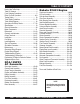
TABLE OF CONTENTS Here's How To Get Help .......................................... 3 Table Of Contents ................................................... 4 Parts Ordering Procedures ..................................... 5 Rules For Safe Operation .................................... 6-9 Towing Safety ........................................................ 10 Trailer Safety Guidelines .................................. 11-15 Trailer Wiring Diagram...........................................
www.multiquip.com PARTS ORDERING PROCEDURES Ordering parts has never been easier! Choose from three easy options: Order via Internet (Dealers Only): Best Deal! Effective: January 1st, 2006 If you have an MQ Account, to obtain a Username and Password, E-mail us at: parts@multiquip. com. Order parts on-line using Multiquip’s SmartEquip website! ■ View Parts Diagrams ■ Order Parts ■ Print Specification Information To obtain an MQ Account, contact your District Sales Manager for more information.
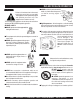
RULES FOR SAFE OPERATION CAUTION: Failure to follow instructions in this manual may lead to serious injury or even death! This equipment is to be operated by trained and qualified personnel only! This equipment is for industrial use only. The following safety guidelines should always be used when operating the DCA-10SPX3 portable generator: GENERAL SAFETY ■ DO NOT operate or service this equipment before reading this entire manual. ■ This equipment should not be operated by persons under 18 years of age.
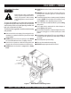
RULES FOR SAFE OPERATION CAUTION: CAUTION: DO NOT touch or open any of the below mentioned components while the generator is running. Always allow sufficient time for the engine and generator to cool before performing maintenance. Radiator ■ NEVER touch output terminals during operation. This is extremely dangerous. Always stop the machine when contact with the output terminals is required. 1.
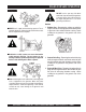
RULES FOR SAFE OPERATION Battery CAUTION: ■ Never over fill the battery with water above the upper limit. The battery has acids that can cause injury to the eyes and skin. To avoid eye irritation, always wear safety glasses. Use well insulated gloves when picking up the battery. Use the following guidelines when handling the battery: 1. DO NOT drop the battery. There is the possibility of risk the battery may explode. 2. DO NOT expose the battery to open flames, sparks, cigarettes etc.
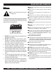
RULES FOR SAFE OPERATION Transporting ■ Always shutdown engine before transporting. ■ Tighten fuel tank cap securely. Maintenance Safety ■ NEVER lubricate components or attempt service on a running machine. ■ Drain fuel when transporting generator over long distances or bad roads. ■ Always allow the machine a proper amount of time to cool before servicing. ■ Always tie-down the generator during transportation by securing the generator. ■ Keep the machinery in proper running condition.
DCA-10SPX3 — TOWING ■ ALWAYS attach trailer's safety chain to bumper of towing vehicle. Towing Safety Precautions CAUTION : Check with your county or state safety towing regulations department before towing your generator. Vehicle towing codes and regulations can vary from state to state. To reduce the possibility of an accident while transporting the generator on public roads, always make sure the trailer and the towing vehicle are in good operating condition and both units are mechanically sound.
DCA-10SPX3 — TRAILER-SAFETY GUIDELINES Frame Length - This measurement is from the ball hitch to the rear bumper (reflector). ALWAYS make sure the trailer is in good 5. Frame Width - This measurement is from fender to operating condition. Check the tires for fender. proper inflation and wear. Also check the 6. Jack Stand - Trailer support device with maximum wheel lug nuts for proper tightness. pound requirement from the tongue of the trailer. 7. Coupler - Type of hitch used on the trailer for towing.
DCA-10SPX3 —TRAILER-SPECIFICATIONS Table 1. Specifications MOD EL APPLIC ATION FU E L C E LL B R AK E SYSTEM GVWR FR AME LEN GTH FR AME WID TH JAC K STAN D TR LR -10-15 TLG-12, D C A15, TLW-300 NO NO 1900LB S 96" 50" 800LB . FULL TILT WHEEL TR LR -10X TLG-12, D C A15, TLW-300 NO NO 1900LB S 96" 50" 800LB . FULL TILT WHEEL TR LR -10XF TLG-12, D C A15, TLW-300 51 GAL NO 1900LB S 96" 50" 800LB . FULL TILT WHEEL TR LR -225W D C A-10 NO NO 2200LB S 85" 42" 800LB .
DCA-10SPX3 —TRAILER-SPECIFICATIONS Table 1.S pecifications (C on't) M O D EL C O U P LE R TIR E S W H E E LS A X LE H U B S S U S P E N S IO N E LE C TR IC A L TR LR -10W 2" B A LL C LA S S 2 A D JU S TA B LE 175-13C 13"X 4.50" 2200# 2X 2 5 LU G 3 LE A F 4 W IR E LO O M W / 4 P O LE FLAT TR LR -10 2"B A LL C LA S S 2 A D JU S TA B LE 175-13C 13"X 4.5" 2200#2X 2 5 LU G 3 LE A F 4 P O LE FLAT TR LR -10X F 2"B A LL C LA S S 2 A D JU S TA B LE 175-13C 13"X 4.
DCA-10SPX3 — TRAILER SAFETY GUIDELINES Tires/Wheels/Lug Nuts Tires and wheels are a very important and critical components of the trailer. When specifying or replacing the trailer wheels it is important the wheels, tires, and axle are properly matched. CAUTION: DO NOT attempt to repair or modify a wheel. DO NOT install in inner tube to correct a leak through the rim.
DCA-10SPX3 — TRAILER SAFETY GUIDELINES Table 3. Suspension Torque Requirements Item Torque (Ft.-Lbs.) 3/8" U-BOLT MIN-30 MAX-35 7/16" U-BOLT MIN-45 MAX-60 1/2" U-BOLT MIN-45 MAX-60 SHACKLE BOLT SNUG FIT ONLY. PARTS MUST ROTATE FREELY. SPRING EYE BOLT LOCKING NUTS OR COTTER PINS ARE PROVIDED TO RETAIN NUT-BOLT ASSEMBLY. MIN-30 MAX-50 SHOULDER TYPE SHACKLE BOLT Lug Nut Torque Requirements It is extremely important to apply and maintain proper wheel mounting torque on the trailer.
DCA-10SPX3 —TRAILER-WIRING DIAGRAM NOTE: LIGHTS ARE ORIENTED FROM THE DRIVER’S SEAT PAGE 16 — DCA-10SPX3 A.C. GENERATOR— PARTS & OPERATION MANUAL — REV.
DCA-10SPX3 —OPERATION AND SAFETY DECALS Machine Safety Decals The DCA10SPX3 generator is equipped with a number of safety decals. These decals are provided for operator safety and maintenance information. The illustration below and on the preceding pages show these decals as they appear on the machine. Should any of these decals become unreadable, replacements can be obtained from your dealer. DCA-10SPX3 A.C. GENERATOR — PARTS & OPERATION MANUAL — REV.
DCA-10SPX3 —OPERATION AND SAFETY DECALS Machine Safety Decals PAGE 18 — DCA-10SPX3 A.C. GENERATOR— PARTS & OPERATION MANUAL — REV.
DCA-10SPX3 — SPECIFICATIONS Table 5. Specifications Generator Specifications Model DCA10SPX3 Type Rotating-Field, Protection Type Synchronous Generator Excitation Brushless Type (With A.V.R) Phase Single Phase Frequency 60 Hz Wires 3-Wires (Neutral Grounded) 10.5 kW/16.5 HP Max. Rated Output @ 1800 rpm 10 kW/16.
DCA-10SPX3 — GENERAL INFORMATION DCA-10SPX3 3 FAMILIARIZATION Generator The MQ Power Model DCA-10SPX3 is a 10 kW generator that is designed as a high quality portable (requires a trailer for transport) power source for telecom sites, lighting facilities, power tools, submersible pumps and other industrial and construction machinery.
DCA-10SPX3 — MAJOR COMPONENTS Figure 4. DCA10SPX3 Generator Major Components DCA-10SPX3 A.C. GENERATOR — PARTS & OPERATION MANUAL — REV.
DCA-10SPX3 — DIMENSIONS (TOP & SIDE) Figure 5a. Dimensions (Top & Side) PAGE 22 — DCA-10SPX3 A.C. GENERATOR— PARTS & OPERATION MANUAL — REV.
DCA-10SPX3 — DIMENSIONS (FRONT, REAR & BOTTOM) Figure 5b. Dimensions (Front, Rear) DCA-10SPX3 A.C. GENERATOR — PARTS & OPERATION MANUAL — REV.
DCA-10SPX3 — CONTROL PANEL, CONTROLS AND INDICATORS Figure 6. Control Panel PAGE 24 — DCA-10SPX3 A.C. GENERATOR— PARTS & OPERATION MANUAL — REV.
DCA-10SPX3 — CONTROL PANEL, CONTROLS AND INDICATORS The definitions below describe the controls and functions of the DCA-10SPX3 (Figure 6): 1. Frequency Meter – Indicates the output frequency in hertz (Hz). Normally 60 Hz ±1 Hz . 2. AC Ammeter – Indicates the amount of current the load is being drawn from the generator. 3. AC Voltmeter – Indicates the single phase output voltage present at the UNV terminals. 4. Engine Warning Display Module – This module displays the following engine failures: A.
DCA10SPX3 OUTPUT TERMINAL FIGURE 7. Output Terminal Panel 120 Volt Recetacle One GFCI Duplex Nema 5-20R (120V, 20 Amp) receptacle is provided on the output terminal. This receptacle can be used anytime the generator is in operation. The receptacle is controlled by the circuit breaker located on the control panel. FIGURE 8. Duplex Receptacle Detail The reset button is for the GFCI when the circuit is tripped.
DCA10SP3X OUTPUT TERMINAL Output Terminal Panel Available Voltages The DCA10SPX3 is a single phase generator only. It is able to supply both 120 volt and 240 volt. Maximum Amps The DCA-10SPX3 can provide 41.7 amps at 120 or 240 volts. Do not exceed the maximum amps! 120V Hard Wire Hookup 240V Hard Wire Hookup The output terminal panel, when suppling single phase 120 volts, will provide two circuits available at 41.7 amps with any two wires plus the ground. (See Figure 10 below.
DCA-10SPX3 — INSTALLATION Outdoor Installation Install the generator in a location where it is not exposed to rain or sunshine. Make sure the generator is on a secure level ground so that it cannot slide or shift around. Also install the generator in a manner so the exhaust will not be discharged in the direction of nearby homes. The installation site must be away from excessive moisture and dust. All electrical equipment should be protected from excessive moisture.
DCA-10SPX3 — INSTALLATION Figure 12. Typical Generator Grounding Application CAUTION : Always check local codes for proper grounding codes and laws. DCA-10SPX3 A.C. GENERATOR — PARTS & OPERATION MANUAL — REV.
DCA-10SPX3 — PRE-SETUP General Inspection Prior to Operation Circuit Breaker The DCA-10SPX3 generator has been thoroughly inspected and accepted prior to shipment from the factory. However, be sure to check for damaged parts or components, or loose nuts and bolts, which could have occurred in transit. Extension Cable When electric power is to provided to loads (ie. power tools) at a distance from the generator, extension cables are used.
DCA-10SPX3 — PRE-SETUP Lubrication Oil Fuel Fill the engine crankcase with lubricating oil through the filler hole, but do not overfill. Make sure the generator is level. With the dipstick inserted all the way, but without being screw into the filler hole, verify that the oil level is maintained between the two notches (Figure 13) on the dipstick. See Table 7 for proper selection of engine oil. Fill the fuel tank with clean and fresh diesel fuel. DO NOT fill the tank beyond capacity.
DCA-10SPX3 — PRE-SETUP CAUTION : When adding coolant or antifreeze to the radiator, do not remove the radiator cap until the unit has completely cooled. Day-to-day addition of coolant is done from the reserve tank. When adding coolant to the radiator, DO NOT remove the radiator cap until the unit has completely cooled. See Table 8. for engine, radiator, and reserve tank coolant capacities. Make sure the coolant level in the reserve tank is always between the "H" and the "L" markings. Table 8.
DCA-10SPX3 — PRE-SETUP Battery This unit is of negative ground. DO NOT connect in reverse. Always maintain battery fluid level between the specified marks. Battery life will be shortened, if the fluid level is not properly maintained. Add only distilled water when replenishment is necessary. DO NOT over fill. The battery is sufficiently charged if the specific gravity of the battery fluid is 1.28 (at 68° F). If the specific gravity should fall to 1.
DCA-10SPX3 — LOAD APPLICATION Single Phase, Load Always be sure to check the nameplate on the generator and equipment to insure the wattage, amperage and frequency requirements are satisfactorily supplied by the generator for operating the equipment. Generally, the wattage listed on the nameplate of the equipment is its rated output.
DCA-10SPX3 — GENERATOR START-UP PROCEDURE WARNING: The engine's exhaust contains harmful emissions. ALWAYS ventilate the exhaust when operating inside tunnels, excavations or buildings. Direct exhaust away from nearby personnel. 2. Connect the load to the UNV terminals as shown in Figure 17. These terminals can be found on the front of the generator by lifting the UNV lug cover. It may be necessary to remove the retaining lug that secures the cover.
DCA-10SPX3 — GENERATOR START-UP PROCEDURE 4. Connect the negative battery cable (BLACK) to the negative post on the battery (Figure 19). 7. The ammeter (Figure 23) will indicate zero amps with no load applied. When a load is applied, this meter will indicate the amount of current that the load is drawing from the generator. 20 40 0 IVE ST PO E TIV GA NE RY E TT A B Figure 19. Battery Connections 5. Close all engine enclosure doors (Figure 20). 60 75 A Figure 23. Ammeter (No Load) 8.
DCA-10SPX3 — GENERATOR SHUT-DOWN PROCEDURE 10. The battery voltage gauge (Figure 26) will indicate the voltage of the battery when the generator is operating. Under normal operating conditions this voltage is between 11.2 and 15.2 volts. Engine Shutdown To shutdown the generator use the following procedure: 1. Place both the MAIN and GFCI circuit breakers to the "OFF position" (Figure 29). CIRCUIT BREAKER MAIN OFF Figure 26. Battery Voltage Gauge 11.
DCA-10SPX3 — MAINTENANCE General Inspection Check Oil Level Prior to each use, the generator should be cleaned and inspected for deficiencies. Check for loose, missing or damaged nuts, bolts or other fasteners. Also check for fuel, oil, and coolant leaks. Check the crankcase oil level prior to each use, or when the fuel tank is filled. Insufficient oil may cause severe damage to the engine. Make sure the generator is level.
DCA-10SPX3 — MAINTENANCE Generator Storage For storage of the generator for over 30 days, the following is required: Fill the fuel tank completely. Completely drain the oil from the crankcase and refill with fresh oil. Clean all external parts of the generator with a cloth. Cover the generating set and store in a clean, dry place.
DCA-10SPX3 —GENERATOR WIRING DIAGRAM PAGE 40 — DCA-10SPX3 A.C. GENERATOR— PARTS & OPERATION MANUAL — REV.
DCA-10SPX3 —ENGINE WIRING DIAGRAM DCA-10SPX3 A.C. GENERATOR — PARTS & OPERATION MANUAL — REV.
DCA-10SPX3 — TROUBLESHOOTING (ENGINE) Practically all breakdowns can be prevented by proper handling and maintenance inspections, but in the event of a breakdown, please take a remedial action following the diagnosis based on the Engine Troubleshooting (Table 11) information shown below and on the proceeding page. If the problem cannot be remedied, consult our company's business office or service plant. TABLE 11. ENGINE TROUBLESHOOTING SYMPTOM Engine does not start.
DCA-10SPX3 — TROUBLESHOOTING (ENGINE) TABLE 11. ENGINE TROUBLESHOOTING (CONTINUED) SYMPTOM Engine revolution is not smooth. Either white or blue exhaust gas is observed. Either black or dark gray exhaust gas is observed. Deficient output. POSSIBLE PROBLEM SOLUTION Fuel filter clogged or dirty? Clean or change. Air cleaner clogged? Clean or change. Fuel leak due to loose injection pipe retaining nut? Tighten nut. Injection pump malfunctioning? Repair or replace.
DCA-10SPX3 — TROUBLESHOOTING (GENERATOR/ENGINE) Practically all breakdowns can be prevented by proper handling and maintenance inspections, but in the event of a breakdown, please take a remedial action following the diagnosis based on the Generator Troubleshooting (Table 12) information shown below and on the proceeding page. If the problem cannot be remedied, consult our company's business office or service plant. TABLE 12.
NOTE PAGE DCA-10SPX3 A.C. GENERATOR — PARTS & OPERATION MANUAL — REV.
EXPLANATION OF CODE IN REMARKS COLUMN How to read the marks and remarks used in this parts book. Items Found In the “Remarks” Column Serial Numbers-Where indicated, this indicates a serial number range (inclusive) where a particular part is used. Model Number-Where indicated, this shows that the corresponding part is utilized only with this specific model number or model number variant.
DCA-10SPX3 — SUGGESTED SPARE PARTS DCA-10SPX3 W/KUBOTA D1403 DIESEL ENGINE 1 TO 3 UNITS QTY. P/N DESCRIPTION 1 ......... 0601820626 ..... AUTOMATIC VOLTAGE REGULATOR 1 ......... 0601807083 ..... MAIN CIRCUIT BREAKER 1 ......... 0601812597 ..... RECEPTACLE CIRCUIT BREAKER 1 ......... 0601840073 ..... VOLTAGE REGULATOR (RHEOSTAT) 3 ......... 1707972062 ..... OIL FILTER 1 ......... 0602122050 ..... OIL SENDING UNIT 1 ......... 0602123251 ..... WATER TEMPERATURE SENDING UNIT 1 ......... 1726697011 .....
DCA-10SPX3 — GENERATOR ASSY. PAGE 48 — DCA-10SPX3 A.C. GENERATOR— PARTS & OPERATION MANUAL — REV.
DCA-10SPX3 — GENERATOR ASSY. GENERATOR ASSY. NO. PART NO. PART NAME QTY.
DCA-10SPX3 — CONTROL PANEL ASSY. CONTROL PANEL ASSY. PAGE 50 — DCA-10SPX3 A.C. GENERATOR— PARTS & OPERATION MANUAL — REV.
DCA-10SPX3 — CONTROL PANEL ASSY. CONTROL PANEL ASSY. NO. PART NO.
DCA-10SPX3 — OUTPUT TERMINAL ASSY. PAGE 52 — DCA-10SPX3 A.C. GENERATOR— PARTS & OPERATION MANUAL — REV.
DCA-10SPX3 — OUTPUT TERMINAL ASSY. OUTPUT TERMINAL ASSY. NO. PART NO.
DCA-10SPX3 — ENGINE & RADIATOR ASSY. PAGE 54 — DCA-10SPX3 A.C. GENERATOR— PARTS & OPERATION MANUAL — REV.
DCA-10SPX3 — ENGINE & RADIATOR ASSY. ENGINE AND RADIATOR ASSY. NO. PART NO. PART NAME QTY. REMARKS 1 0805096804 HOSE BAND 1 2 0605515094 HOSE BAND 3 3 0802081104 CAP, RESERVE TANK 1 4 7222016304 HOSE BAND 1 5 0802081403 RESERVE TANK 1 6 1707611010 AIR CLEANER ............................................. 1 7 8322031004 BRACKET, AIR CLEANER 1 8 011008020 HEX. HEAD BOLT 6 9 3426013960 BAND, AIR CLEANER ................................. 1 10 011208030 HEX. HEAD BOLT 2 11 011006010 HEX.
DCA-10SPX3 — BATTERY ASSY. BATTERY ASSY. PAGE 56 — DCA-10SPX3 A.C. GENERATOR— PARTS & OPERATION MANUAL — REV.
DCA-10SPX3 — BATTERY ASSY. BATTERY ASSY. NO. PART NO. PART NAME 1 2 BATTERY .................. 1 ...... 65D31R BATTERY FRAME 1 LINING 1 HEX HEAD BOLT 5 BATTERY SHEET 1 BATTERY BAND 1 BATTERY BOLT 1 HEX HEAD BOLT 2 BATTERY BOLT 1 WING NUT 2 LOCK WASHER 2 PLAIN WASHER 2 BATTERY CABLE 1 BATTERY CABLE 1 EARTH CABLE 1 TERMINAL ASS’Y. .... 1 ...... NO.9P TERMINAL ASS’Y. .... 1 ...... NO.9N TERMINAL CAP ........ 1 ......
DCA-10SPX3 — MUFFLER ASSY. PAGE 58 — DCA-10SPX3 A.C. GENERATOR— PARTS & OPERATION MANUAL — REV.
DCA-10SPX3 — MUFFLER ASSY. MUFFLER ASSY. NO. PART NO. PART NAME 1 2 3 4 5 6 7 8342311003 0017108020 8342350103 0602320150 1502336004 020108060 011208035 MUFFLER 1 HEX HEAD BOLT 6 EXHAUST PIPE 1 GASKET ......................................... 1 .......... KUBOTA 15471-12231 GASKET 1 HEX NUT 4 HEX HEAD BOLT 2 QTY. REMARKS DCA-10SPX3 A.C. GENERATOR — PARTS & OPERATION MANUAL — REV.
DCA-10SPX3 — FUEL FILTER ASSY. FUEL FILTER ASSY. PAGE 60 — DCA-10SPX3 A.C. GENERATOR— PARTS & OPERATION MANUAL — REV.
DCA-10SPX3 — FUEL FILTER ASSY. FUEL FILTER ASSY. NO. 1 2 3 4 5 6 7 8 9 10 11 12 13 14 15 PART NO. 0966141000 1024442320 0605513105 0017106016 B0368700004 0017108020 1491142750 6837151210 0017108035 1522143010 7000043081 011208025 7675528004 0966181000 0605513106 PART NAME QTY. REMARKS RETURN HOSE 1 HOSE BAND ................................... 2 .......... REPLACES SUCTION HOSE 1 HEX.HEAD BOLT 2 BRACKET, FUEL FILTER 1 HEX. HEAD BOLT ........................... 2 .......... REPLACES HOSE BAND .............
DCA-10SPX3 — ENCLOSURE ASSY. ENCLOSURE ASSY. ADD THE FOLLOWING DIGITS AFTER THE PART NUMBER WHEN ORDERING ANY PAINTED PANEL TO INDICATE COLOR OF UNIT IF NOT IN TEAL: MQW-WHITE SK-SCARLET/ORANGE THE SERIAL NUMBER MAY BE REQUIRED. PAGE 62 — DCA-10SPX3 A.C. GENERATOR— PARTS & OPERATION MANUAL — REV.
DCA-10SPX3 — ENCLOSURE ASSY. ENCLOSURE ASSEMBLY NO. PART NO.
DCA-10SPX3 — ENCLOSURE (RUBBER SEALS) ASSY. ENCLOSURE (SEALS )ASSY. PAGE 64 — DCA-10SPX3 A.C. GENERATOR— PARTS & OPERATION MANUAL — REV.
DCA-10SPX3 — ENCLOSURE (RUBBER SEALS) ASSY. ENCLOSURE (RUBBER SEALS )ASSY. NO. 1 2 3 4 5 6 7 8 9 PART NO. 0229400650 0229400895 0229200650 0220400650 0227600895 0229400265 0229400550 0229200580 0229200245 PART NAME RUBBER SEAL RUBBERSEAL RUBBER SEAL RUBBER SEAL RUBBER SEAL RUBBER SEAL RUBBER SEAL RUBBER SEAL RUBBER SEAL QTY. 3 2 1 2 2 2 1 2 2 REMARKS DCA-10SPX3 A.C. GENERATOR — PARTS & OPERATION MANUAL — REV.
DCA-10SPX3 — NAME PLATE AND DECALS NAME PLATE AND DECALS PAGE 66 — DCA-10SPX3 A.C. GENERATOR— PARTS & OPERATION MANUAL — REV.
DCA-10SPX3 — NAME PLATE AND DECALS NAME PLATE AND DECALS NO. PART NO. PART NAME 1 2 3 4 5 6 7 8 9 10 11 12 13 14 15 16 17 18 19 20 21 22 23 WARNING! TRANSFER SWITCH 1 IMPORTANT “CHECK DAILY” 1 DANGER: ELEC.
KUBOTA D1403— CRANKCASE ASSY. CRANKCASE ASSY. PAGE 68 — DCA-10SPX3 A.C. GENERATOR— PARTS & OPERATION MANUAL — REV.
KUBOTA D1403— CRANKCASE ASSY. CRANKCASE ASSY. NO. 010 020* 030* 040* 050* 060* 070* 080* 090* 100* 110* 120* 130* 140* 150 160 170 180 190 200 210 220 230 240 250 260 PART NO. 1641401010 3415027580 3221027580 1552196020 1552196030 1739196160 0631175045 1522103383 1522103392 0501200408 0501200609 0501200612 0501201018 1522133650 1522133610 1502133660 1522133700 1532173340 1547135010 1529635150 0105350650 0451260060 1920235660 0571200410 1522135682 1584139010 PART NAME QTY. REMARKS COMP. CRANKCASE .........
KUBOTA D1403— OIL PAN ASSY. OIL PAN ASSY. PAGE 70 — DCA-10SPX3 A.C. GENERATOR— PARTS & OPERATION MANUAL — REV.
KUBOTA D1403— OIL PAN ASSY. OIL PAN ASSY. NO. 010 020 030 040 050 060 070 080 090 100 110 PART NO. 1929901613 1531301620 1733391010 152133750 7000065259 1595133750 0472400160 1562832110 0112360814 0481100160 1711136410 PART NAME QTY. REMARKS OIL PAN 1 OIL PAN GASKET 1 FLANGE BOLT 20 PLUG 1 GASKET ...................................... 1 ... REPLACES 1510933660 DRAIN PLUG 1 GASKET 1 OIL FILTER 1 BOLT 1 O RING 1 OIL GAUGE 1 DCA-10SPX3 A.C. GENERATOR — PARTS & OPERATION MANUAL — REV.
KUBOTA D1403— CYLINDER HEAD ASSY. CYLINDER HEAD ASSY. PAGE 72 — DCA-10SPX3 A.C. GENERATOR— PARTS & OPERATION MANUAL — REV.
KUBOTA D1403— CYLINDER HEAD ASSY. CYLINDER HEAD ASSY. NO. 010 020 030 040 050 060 070 080 090* 100* 110* 120* 130* 140 150 160 PART NO. 1522101750 1641501752 0112360816 1547191530 0215650080 0451260080 0401250080 1641403040 1522103370 1522103490 1526196010 1732113580 1732113560 1901303450 1642703310 1949883040 PART NAME QTY. REMARKS ENGINE HOOK 1 ENGINE HOOK 1 BOLT 1 STUD 1 NUT 1 LOCK WASHER 1 PLAIN WASHER 1 COMP. CYLINDER HEAD ............. 1 ...
KUBOTA D1403— GEAR CASE ASSY. GEAR CASE ASSY. PAGE 74 — DCA-10SPX3 A.C. GENERATOR— PARTS & OPERATION MANUAL — REV.
KUBOTA D1403— GEAR CASE ASSY. GEAR CASE ASSY. NO. 010 020* 030* 040* 050* 060* 070 080 090 100 110 120 130 140 150 160 170 180 190 200 210 220 230 240 250 260 270 280 290 300 310 PART NO.
KUBOTA D1403— MAIN BEARING CASE ASSY. MAIN BEARING CASE ASSY. PAGE 76 — DCA-10SPX3 A.C. GENERATOR— PARTS & OPERATION MANUAL — REV.
KUBOTA D1403 — MAIN BEARING CASE ASSY. MAIN BEARING CASE ASSY. NO. 010 020 030 040 050 060 070 080 090 100 110 120 PART NO. 1901304090 1901304540 1907704360 1901304813 1711804830 0112350825 0112350828 1920204460 1901304040 1901304050 1901304060 1560104560 PART NAME MAIN BEARING CASE ASSY. BEARING CASE BOLT BEARING CASE GASKET BEARING CASE COVER CASE COVER GASKET BOLT BOLT OIL SEAL MAIN BEARING CASE ASSY. MAIN BEARING CASE ASSY. MAIN BEARING CASE ASSY. BEARING CASE BOLT QTY.
KUBOTA D1403— INLET MANIFOLD ASSY. INLET MANIFOLD ASSY. PAGE 78 — DCA-10SPX3 A.C. GENERATOR— PARTS & OPERATION MANUAL — REV.
KUBOTA D1403— INLET MANIFOLD ASSY. INLET MANIFOLD ASSY. NO. 010 020 030 040 PART NO. 1718211760 1718205550 1732611820 0112350822 PART NAME INLET MANIFOLD BREATHER JOINT IN-MANIFOLD GASKET BOLT QTY. REMARKS 1 1 1 5 DCA-10SPX3 A.C. GENERATOR — PARTS & OPERATION MANUAL — REV.
KUBOTA D1403— EXHAUST MANIFOLD ASSY. EXHAUST MANIFOLD ASSY. PAGE 80 — DCA-10SPX3 A.C. GENERATOR— PARTS & OPERATION MANUAL — REV.
KUBOTA D1403— EXHAUST MANIFOLD ASSY. EXHAUST MANIFOLD ASSY. NO. 010 020 030 040 050 060 PART NO. 1927412312 1531312350 1522191530 1642992010 151350822 1526312370 PART NAME EXHAUST MANIFOLD EX-MANIFOLD GASKET STUD NUT STUD MUFFLER GASKET QTY. 1 1 6 6 4 1 REMARKS DCA-10SPX3 A.C. GENERATOR — PARTS & OPERATION MANUAL — REV.
KUBOTA D1403— VALVE AND ROCKER ASSY. VALVE AND ROCKER ASSY. PAGE 82 — DCA-10SPX3 A.C. GENERATOR— PARTS & OPERATION MANUAL — REV.
KUBOTA D1403— VALVE AND ROCKER ASSY. VALVE AND ROCKER ASSY. NO. 010 020 030 040 050 060 070 080 090* 100 110 120 130 140 150 160 170 180 190 200# 210# PART NO. 1648413110 1648413120 1522113240 1522113330 1522113360 1522113150 1522113280 1540114052 0341000808 1522114350 1552191500 0215650080 0451260080 0401250080 0541100528 1522114430 1522114310 0461200140 1562114030 1552114230 1502114240 PART NAME QTY.
KUBOTA D1403— HEAD COVER ASSY. HEAD COVER ASSY. PAGE 84 — DCA-10SPX3 A.C. GENERATOR— PARTS & OPERATION MANUAL — REV.
KUBOTA D1403— HEAD COVER ASSY. HEAD COVER ASSY. NO. 010 020 030 040 PART NO. 1718214510 1552114520 1718205020 1711405130 PART NAME HEAD COVER HEAD COVER GASKET COMP. BREATHER GASKET 050 060 070 080 090 100 110 0112350840 1624105670 1718214490 1718205510 0931888200 1545192330 1502133660 BOLT BREATHER ELEMENT PLATE BREATHER TUBE HOSE CLAMP CAP NUT GASKET QTY. 1 1 1 REMARKS 2 2 1 1 1 2 3 3 DCA-10SPX3 A.C. GENERATOR — PARTS & OPERATION MANUAL — REV.
KUBOTA D1403— CAMSHAFT ASSY. CAMSHAFT ASSY. PAGE 86 — DCA-10SPX3 A.C. GENERATOR— PARTS & OPERATION MANUAL — REV.
KUBOTA D1403— CAMSHAFT ASSY. CAMSHAFT ASSY. NO. 010 020 030 040* 050* 060* 070* 080* 090 100 110# 120 130 140 150 160 PART NO. 1560115550 1901315110 1733116010 1733116150 1552193610 1552116510 0571200720 1522116270 0112350818 1522124010 1642724980 1552124360 1552124370 1522124320 1981824250 0112350818 PART NAME QTY. REMARKS TAPPET 6 PUSH ROD 6 CAMSHAFT ASSY. ........................ 1 ....... INCLUDES ITEMS W/* CAMSHAFT 1 SET SCREW 1 CAM GEAR 1 FEATHER KEY 1 CAMSHAFT STOPPER 1 BOLT 2 IDLE COMP. GEAR .....
KUBOTA D1403— PISTON AND CAMSHAFT ASSY. PISTON AND CAMSHAFT ASSY. PAGE 88 — DCA-10SPX3 A.C. GENERATOR— PARTS & OPERATION MANUAL — REV.
KUBOTA D1403— PISTON AND CAMSHAFT ASSY. PISTON AND CRANKSHAFT ASSY. NO. 010 010 020 020 030 040 050 060* 070* 080* 080 080 090 100# 110# 120 130 140 150 160 170 180 180 180 190 190 190 200 200 200 210 210 210 220 PART NO.
KUBOTA D1403— FLYWHEEL ASSY. FLYWHEEL ASSY. PAGE 90 — DCA-10SPX3 A.C. GENERATOR— PARTS & OPERATION MANUAL — REV.
KUBOTA D1403— FLYWHEEL ASSY. FLYWHEEL ASSY. NO. 010 020* 030 040 050 060 070 080 100 110 120 PART NO. 1722225010 1560263820 1532125163 1747504610 0152104680 1552104790 0112360816 0107351032 0451260100 0107351250 0451260120 PART NAME QTY. REMARKS FLYWHEEL COMP. .................... 1 ............. INCLUDES ITEMS W/* RING GEAR 1 FLYWHEEL BOLT 6 FLYWHEEL HOUSING 1 COVER 1 COVER PACKING 1 BOLT 2 BOLT 11 LOCK WASHER 11 BOLT 2 LOCK WASHER 2 DCA-10SPX3 A.C. GENERATOR — PARTS & OPERATION MANUAL — REV.
KUBOTA D1403— STARTER ASSY. STARTER ASSY. PAGE 92 — DCA-10SPX3 A.C. GENERATOR— PARTS & OPERATION MANUAL — REV.
KUBOTA D1403— STARTER ASSY. STARTER ASSY. NO. 010 020 030 040 050 060 070 PART NO. 7000065440 0151751028 0113351030 0217650100 0451260100 0211450080 0451260080 PART NAME QTY. REMARKS STARTER ASSY. ............................ 1 ....... REPLACES 1738163012 STUD 1 BOLT 1 NUT 1 LOCK WASHER 1 NUT 1 LOCK WASHER 1 DCA-10SPX3 A.C. GENERATOR — PARTS & OPERATION MANUAL — REV.
KUBOTA D1403— STARTER (COMPONENTS) ASSY. STARTER (COMPONENTS) ASSY. PAGE 94 — DCA-10SPX3 A.C. GENERATOR— PARTS & OPERATION MANUAL — REV.
KUBOTA D1403— STARTER (COMPONENTS) ASSY. STARTER (COMPONENTS) ASSY. NO. 010 PART NO. 7000065440 020* 030* 040*# 050*# 060* 070* 080* 090* 100* 110*% 120* 130* 140* 150* 160* 170* 180* 190* 200* 210* 220* 1119763080 1119763070 1146063500 1146063530 1562163040 1648463030 1648463020 1648463200 1738163380 1540163390 1146063270 1146063110 1921263100 1146063120 1921297130 1146093310 1551196660 1119763320 1551163760 1628563570 1396392010 PART NAME QTY. REMARKS STARTER ASSY. ............................ 1 .....
KUBOTA D1403— INJECTION PUMP 1 ASSY. INJECTION PUMP 1 ASSY. PAGE 96 — DCA-10SPX3 A.C. GENERATOR— PARTS & OPERATION MANUAL — REV.
KUBOTA D1403— INJECTION PUMP 1 ASSY. INJECTION PUMP 1 ASSY. NO. 010 020 020 020 040 050 060 070 080 090 100* 110 120 130 140 150# PART NO. 1718251010 1641452090 1641452110 1641452120 0112350822 1522191530 0215650080 0451260080 1574860570 1712152030 1984452040 1526352140 0102350616 1411142410 1468142010 1430142750 PART NAME QTY. REMARKS INJECTION PUMP ASSY. 1 INJECTION SHIM .......................... 1 ....... 0.20MM INJECTION SHIM .......................... 1 ....... 0.25MM INJECTION SHIM ................
KUBOTA D1403— INJECTION PUMP 2 ASSY. INJECTION PUMP 2 ASSY. PAGE 98 — DCA-10SPX3 A.C. GENERATOR— PARTS & OPERATION MANUAL — REV.
KUBOTA D1403— INJECTION PUMP 2 ASSY. INJECTION PUMP ASSY. 2 NO. 010 020* 030* 040* 050* 060* 070* 080* 090* 100* 110* 120* 130* 140* 150* 180* 190* 200* 210* PART NO. 1718251010 1718251050 1647551030 1647551230 1142051240 1641551220 1641551610 1522151070 1461151250 1948451460 1522151280 1522151270 1522151290 1907751490 1718251060 1707951380 1552151320 1522196650 1461151200 PART NAME QTY. REMARKS INJECTION PUMP ASSY. ............. 1 .......
KUBOTA D1403— FUEL CAMSHAFT ASSY. FUEL CAMSHAFT ASSY. PAGE 100 — DCA-10SPX3 A.C. GENERATOR— PARTS & OPERATION MANUAL — REV.
KUBOTA D1403— FUEL CAMSHAFT ASSY. FUEL CAMSHAFT ASSY. NO. 010 020* 030* 040* 050* 060* 070* 080* 090* 100* 110* 120* 140*# 150*# 160* 170* 180* 190 200 210 220 PART NO. 1718216020 1718216170 0815306205 1666251150 0571200525 0461200240 1981855450 1981855460 1981855510 1981855260 1666255270 1666255060 1981855280 198185380 166255620 1981855600 1981855340 0810306205 152216320 0112360814 0461200250 PART NAME QTY. REMARKS FUEL CAMSHAFT ASSY. .............. 1 .......
KUBOTA D1403— GOVERNOR ASSY. GOVERNOR ASSY. PAGE 102 — DCA-10SPX3 A.C. GENERATOR— PARTS & OPERATION MANUAL — REV.
KUBOTA D1403— GOVERNOR ASSY. GOVERNOR ASSY. NO. 010 020* 030* 040* 050* 060* 070* 080* 090 100 110 120 130 140 150 160 170 PART NO. 1718256050 1707656130 1981856150 0105350518 0451260050 1707656230 1522166410 0451260060 0112350832 0102350628 0401250080 0401250060 1981856480 1718256412 1718256420 1981855600 1981855340 PART NAME QTY. REMARKS FORK LEVER ASSY. ..................... 1 .......
KUBOTA D1403— SPEED CONTROL PLATE ASSY. SPEED CONTROL PLATE ASSY. PAGE 104 — DCA-10SPX3 A.C. GENERATOR— PARTS & OPERATION MANUAL — REV.
KUBOTA D1403— SPEED CONTROL PLATE ASSY. SPEED CONTROL PLATE ASSY. NO. 010 020 030 040 050 070 080 090 100 110 120 130 140 150 160 170 180 190 200 210 220 230 240 250 PART NO.
KUBOTA D1403— ENGINE STOP LEVER ASSY. ENGINE STOP LEVER ASSY. PAGE 106 — DCA-10SPX3 A.C. GENERATOR— PARTS & OPERATION MANUAL — REV.
KUBOTA D1403 — ENGINE STOP LEVER ASSY. ENGINE STOP LEVER ASSY. NO. 010 020* 030* 040* 050* 060* 070 080# 090# 100# 110# 120# 130# 140 150 160 170 180 190 200 210 220 PART NO. 1707654093 1707654103 1540192010 1552192330 1502133660 1552154270 1748257702 1718351650 1733157740 1748257720 1547157980 0541100420 1748257920 1510857280 0205650060 1529651660 0102350618 0102350622 0401250060 1718316210 3539437860 0112350865 PART NAME QTY. REMARKS IDILING APPARATUS ..................... 1 .......
KUBOTA D1403— STOP SOLENOID ASSY. STOP SOLENOID ASSY. PAGE 108 — DCA-10SPX3 A.C. GENERATOR— PARTS & OPERATION MANUAL — REV.
KUBOTA D1403— STOP SOLENOID ASSY. STOP SOLENOID ASSY. NO. 010 020 030 040 050 060 070 080 PART NO. 1547160010 0112360816 0401250080 1733160150 1547160162 0401250060 0552550600 1718260110 PART NAME STOP SOLENOID BOLT PLAIN WASHER STOP LEVER STOP LEVER PLAIN WASHER SNAP PIN SOLENOID SUPPORT QTY. 1 2 2 1 1 3 3 1 REMARKS DCA-10SPX3 A.C. GENERATOR — PARTS & OPERATION MANUAL — REV.
KUBOTA D1403 — ALTERNATOR ASSY. ALTERNATOR ASSY. PAGE 110 — DCA-10SPX3 A.C. GENERATOR— PARTS & OPERATION MANUAL — REV.
KUBOTA D1403 — ALTERNATOR ASSY. ALTERNATOR ASSY. NO. 010 020 030 040 050 060 070 080 090 100 110 PART NO. 1642764010 TA04074020 0117351000 0115360830 0451260080 0215650100 0451260100 0401150100 0401560080 0205650060 0451260060 PART NAME ALTERNATOR ASSY. DYNAMO STAY BOLT BOLT LOCK WASHER NUT LOCK WASHER PLAIN WASHER PLAIN WASHER NUT LOCK WASHER QTY. 1 1 1 1 1 1 1 1 1 1 1 REMARKS DCA-10SPX3 A.C. GENERATOR — PARTS & OPERATION MANUAL — REV.
KUBOTA D1403— ALTERNATOR (COMPONENTS) ASSY. ALTERNATOR (COMPONENTS) ASSY. PAGE 112 — DCA-10SPX3 A.C. GENERATOR— PARTS & OPERATION MANUAL — REV.
KUBOTA D1403— ALTERNATOR (COMPONENTS) ASSY. ALTERNATOR (COMPONENTS) ASSY. NO. 010 020* 030* 040* 050* 060*# 070*# 090* 100* 110*% 120*% 130*% 140*% 150* 160* 170* 180* 190*& 200*& 210* 220* 230* 240* 250* 260* 270* 280* PART NO.
KUBOTA D1403— FAN ASSY. FAN ASSY. PAGE 114 — DCA-10SPX3 A.C. GENERATOR— PARTS & OPERATION MANUAL — REV.
KUBOTA D1403— FAN ASSY. FAN ASSY. NO. 010 020 030 040 050 060 PART NO. 1734574110 1981874150 0175450625 1728874280 0571200720 1726697011 PART NAME QTY. REMARKS FAN 1 FAN COLLAR 1 FLANGE BOLT 4 FAN DRIVE PULLEY 1 FEATHER KEY 1 V BELT ........................................... 1 ....... REPLACES 1726697010 DCA-10SPX3 A.C. GENERATOR — PARTS & OPERATION MANUAL — REV.
KUBOTA D1403 — WATER FLANGE AND THERMOSTAT ASSY. WATER FLANGE AND THERMOSTAT ASSY. PAGE 116 — DCA-10SPX3 A.C. GENERATOR— PARTS & OPERATION MANUAL — REV.
KUBOTA D1403 — WATER FLANGE AND THERMOSTAT ASSY. WATER FLANGE AND THERMOSTAT ASSY. NO. 010 020* 030 040 050 060 070 080 090 100 110 120 130 140 150 160 PART NO. 1551272702 1733173342 1576672920 0112350822 0151350822 0115350870 0215650080 0451260080 1552173340 1510973360 1532173260 1531373270 0112350835 1943473010 1551296010 0471702150 PART NAME QTY. REMARKS WATER FLANGE COMP. ................ 1 .......
KUBOTA D1403— WATER PUMP ASSY. WATER PUMP ASSY. PAGE 118 — DCA-10SPX3 A.C. GENERATOR— PARTS & OPERATION MANUAL — REV.
KUBOTA D1403— WATER PUMP ASSY. WATER PUMP ASSY. NO. 010 020* 030* 040* 050* 060 070 080 090 100 110 120 PART NO. 1552173033 1552173550 1666173510 1666173050 1552173520 1576673430 0112350828 1552191510 0451260080 0215650080 0102350618 1547174250 PART NAME QTY. REMARKS WATER PUMP ASSY. .................... 1 ....... INCLUDES ITEMS W/* BEARING 1 IMPELLER 1 MECHANICAL SEAL ASSY. 1 WATER PUMP FLANGE 1 WATER PUMP GASKET 1 BOLT 2 STUD 2 LOCK WASHER 2 NUT 2 BOLT 8 FAN PULLEY 1 DCA-10SPX3 A.C.
KUBOTA D1403— RADIATOR ASSY. RADIATOR ASSY. PAGE 120 — DCA-10SPX3 A.C. GENERATOR— PARTS & OPERATION MANUAL — REV.
KUBOTA D1403— RADIATOR ASSY. RADIATOR ASSY. NO. 010 020* 030* 040* 050* 060 070 080 090 100 110 120 130*# PART NO. 1559672060 1552172330 1527272020 1559672710 1547172730 1546172850 170637294 1510872870 1553772410 1718273340 1540111720 1430142750 1907787240 PART NAME QTY. REMARKS RADIATOR ASSY. .......................... 1 ....... INCLUDES ITEMS W/* FAN SHROUD 1 CAP ASSY. .................................... 1 .......
KUBOTA D1403 — FUEL FILTER ASSY. FUEL FILTER ASSY. PAGE 122 — DCA-10SPX3 A.C. GENERATOR— PARTS & OPERATION MANUAL — REV.
KUBOTA D1403 — FUEL FILTER ASSY. FUEL FILTER ASSY. NO. 010 030* 040* 050* 060* 070* 080* 090* 100* 110*# 120* 130* 140* 150* PART NO. 1707643012 1552143522 1552143672 1552143552 1552143542 0481110290 1552193310 1552143150 1552143100 1687388430 1552143160 0481150650 1552143930 0481100160 PART NAME QTY. REMARKS FUEL FILTER ASSY. ...................... 1 ....... INCLUDES ITEMS W/* FILTER HANDLE 1 GASKET 1 HANDLE RETAINER 1 THRUST PLATE 1 O RING 1 WASHER WITH SCREW 2 RETAINER RING 1 FILTER CUP ASSY. .........
TERMS AND CONDITIONS OF SALE — PARTS PAYMENT TERMS 5. Parts must be in new and resalable condition, in the original Multiquip package (if any), and with Multiquip part numbers clearly marked. 6. The following items are not returnable: Multiquip reserves the right to quote and sell direct to Government agencies, and to Original Equipment Manufacturer accounts who use our products as integral parts of their own products. a. SPECIAL EXPEDITING SERVICE Terms of payment for parts are net 30 days.
NOTE PAGE DCA-10SPX3 A.C. GENERATOR — PARTS & OPERATION MANUAL — REV.
PARTS AND OPERATION MANUAL OPERATION AND PARTS MANUAL HERE’S HOW TO GET HELP PLEASE HAVE THE MODEL AND SERIAL NUMBER ON-HAND WHEN CALLING UNITED STATES Multiquip Corporate Office 18910 Wilmington Ave. Carson, CA 90746 Contact: mq@multiquip.com MQ Parts Department Tel.