OPERATION AND PARTS MANUAL WHISPERWATT™ SERIES MODEL DCA150SSJU3 50HZ GENERATOR (JOHN DEERE 6068HF285 DIESEL ENGINE) PARTS LIST NO. M3870301104 Revision #1 (02/01/10) To find the latest revision of this publication, visit our website at: www.mqpower.com THIS MANUAL MUST ACCOMPANY THE EQUIPMENT AT ALL TIMES.
PROPOSITION 65 WARNING Diesel engine exhaust and some of PAGE 2 — DCA150SSJU3 50 HZ GENERATOR • OPERATION AND PARTS MANUAL — REV.
REPORTING SAFETY DEFECTS If you believe that your vehicle has a defect that could cause a crash or could cause injury or death, you should immediately inform the National Highway Traffic Safety Administration (NHTSA) in addition to notifying Multiquip at 1-800-421-1244. If NHTSA receives similar complaints, it may open an investigation, and if it finds that a safety defect exists in a group of vehicles, it may order a recall and remedy campaign.
TABLE OF CONTENTS DCA150SSJU3 Generator Component Drawings Proposition 65 Warning ........................................... 2 Reporting Safety Defects......................................... 3 Table Of Contents .................................................... 4 Parts Ordering Procedures ...................................... 5 Safety Information .............................................. 6-11 Specifications ........................................................ 12 Dimensions ................
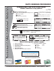
www.mqpower.com PARTS ORDERING PROCEDURES Ordering parts has never been easier! Choose from three easy options: Order via Internet (Dealers Only): Best Deal! Effective: January 1st, 2006 If you have an MQ Account, to obtain a Username and Password, E-mail us at: parts@multiquip. com. Order parts on-line using Multiquip’s SmartEquip website! N View Parts Diagrams N Order Parts N Print Specification Information To obtain an MQ Account, contact your District Sales Manager for more information.
SAFETY INFORMATION Do not operate or service the equipment before reading the entire manual. Safety precautions should be followed at all times when operating this equipment. Failure to read and understand the safety messages and operating instructions could result in injury to yourself and others. Potential hazards associated with the operation of this equipment will be referenced with hazard symbols which may appear throughout this manual in conjunction with safety messages.
SAFETY INFORMATION GENERAL SAFETY CAUTION NEVER operate this equipment without proper protective clothing, shatterproof glasses, respiratory protection, hearing protection, steel-toed boots and other protective devices required by the job or city and state regulations. NEVER operate this equipment when not feeling well due to fatigue, illness or when under medication. NEVER operate this equipment under the influence of drugs or alcohol.
SAFETY INFORMATION ENGINE SAFETY DANGER The engine fuel exhaust gases contain poisonous carbon monoxide. This gas is colorless and odorless, and can cause death if inhaled. The engine of this equipment requires an adequate free flow of cooling air. NEVER operate this equipment in any enclosed or narrow area where free flow of the air is restricted. If the air flow is restricted it will cause injury to people and property and serious damage to the equipment or engine.
SAFETY INFORMATION FUEL SAFETY DANGER DO NOT start the engine near spilled fuel or combustible fluids. Diesel fuel is extremely flammable and its vapors can cause an explosion if ignited. Make sure the hitch and coupling of the towing vehicle are rated equal to, or greater than the trailer “gross vehicle weight rating.” ALWAYS inspect the hitch and coupling for wear. NEVER tow a trailer with defective hitches, couplings, chains, etc.
SAFETY INFORMATION ELECTRICAL SAFETY DANGER DO NOT touch output terminals during operation. Contact with output terminals during operation can cause electrocution, electrical shock or burn. The electrical voltage required to operate the generator can cause severe injury or even death through physical contact with live circuits. Turn generator and all circuit breakers OFF before performing maintenance on the generator or making contact with output terminals.
SAFETY INFORMATION BATTERY SAFETY DANGER DO NOT drop the battery. There is a possibility that the battery will explode. DO NOT expose the battery to open flames, sparks, cigarettes, etc. The battery contains combustible gases and liquids. If these gases and liquids come into contact with a flame or spark, an explosion could occur. ENVIRONMENTAL SAFETY NOTICE Dispose of hazardous waste properly. Examples of potentially hazardous waste are used motor oil, fuel and fuel filters.
SPECIFICATIONS Model Type Armature Connection Phase Standby Output Prime Output Voltage Frequency Speed Power Factor Aux. AC Power Voltage Output Weight (No Fuel) Weight (Fuel) Model Type No. of Cylinders Bore x Stroke Displacement Starting Coolant Capacity Lube Oil Capacity Fuel Type Fuel Tank Capacity Battery Table 1.
DIMENSIONS Figure 1. Dimensions Table 3. Dimensions Reference Letter Dimension in. (mm) A B Reference Letter Dimension in. (mm) 35.03 in. (890 mm.) F 128.98 in. (3,200 mm.) 35.03 in. (890 mm.) G 59.06 in. (1,500 mm.) C 39.76 in. (1,010 mm.) H 47.24 in. (1,200 mm.) D 39.76 in. (1,010 mm.) E 42.12 in. (1,070 mm.) DCA150SSJU3 50 HZ GENERATOR • OPERATION AND PARTS MANUAL — REV.
INSTALLATION Figure 2. Typical Generator Grounding Application PAGE 14 — DCA150SSJU3 50 HZ GENERATOR • OPERATION AND PARTS MANUAL — REV.
INSTALLATION OUTDOOR INSTALLATION GENERATOR GROUNDING Install the generator in a area that is free of debris, bystanders, and overhead obstructions. Make sure the generator is on secure level ground so that it cannot slide or shift around. Also install the generator in a manner so that the exhaust will not be discharged in the direction of nearby homes. To guard against electrical shock and possible damage to the equipment, it is important to provide a good EARTH ground.
GENERAL INFORMATION GENERATOR OPEN DELTA EXCITATION SYSTEM The MQ Power Model DCA-150SSJU3 generator (Figure 3) is a high quality portable (requires a trailer for transport) power source for telecom sites, lighting facilities, power tools, submersible pumps and other industrial and construction machinery. This generator is equipped with the state of the art “OpenDelta” excitation system.
MAJOR COMPONENTS Table 4. Generator Major Components ITEM NO. DESCRIPTION 1 Muffler Assembly 2 Air Filter Assembly 3 Output Terminal Assembly 4 Output Receptacles Assembly 5 Generator Assembly 6 Engine Assembly 7 Battery Assembly 8 Fuel Tank Assembly 9 Circuit Breaker Assembly 10 Engine Control Panel Assembly 11 Generator Control Panel Assembly Figure 3. Major Components DCA150SSJU3 50 HZ GENERATOR • OPERATION AND PARTS MANUAL — REV.
DIAGNOSTIC DISPLAY 2. Left Arrow Button – Press this button to scroll through the screen either moving the parameter selection toward the left or upward. 3. Right Arrow Button – Press this button to scroll through the screen either moving the parameter selection toward the right or downward. 4. Enter Key Button – Press this button to select the parameter that is highlighted on the screen. 5. Emergency Stop LED – When lit (RED) indicates a major fault has occured. This condition will shudown the generator.
DIAGNOSTIC DISPLAY First Time Start Up 1. When power is first applied to the diagnostic display, the “Logo” is displayed. 2. The first seven items of the “Main Menu” will be displayed. Touching the “Arrow Buttons” will scroll through the menu selection. GO TO 1-UP DISPLAY LANGUAGES STORED CODES ENGINE CONFG SETUP 1-UP DISPLAY SETUP-4-UP DISPLAY SELECT UNITS 2. The “Wait to Start” message will be displayed for engines with a pre-startup sequence.
DIAGNOSTIC DISPLAY 2. The language choices will be displayed. Use the “Arrow” buttons to scroll through the selections and touch “Enter” to make a selection. 4. If the word “MORE” appears above the “Arrow Buttons” there are more stored fault codes that may be viewed. Use the “Arrow Buttons” to scroll to the next Stored Diagnostic Code. ENGLISH ESPANOL FRANCAIS DEUTSCH 1 of x SPN110 FMI10 HIGH COOLANT TEMP MORE HIDE 3.
DIAGNOSTIC DISPLAY First Time Start-Up 1. When power is first applied to the diagnostic display, the “Logo” is displayed. 2. The The first seven items of the “Main Menu” will be displayed. Touching the “Arrow Buttons” will scroll through thr menu selection. GO TO 1-UP DISPLAY LANGUAGES STORED CODES ENGINE CONFG SETUP 1-UP DISPLAY SETUP-4-UP DISPLAY SELECT UNITS 2. The “Wait to Start” message will be displayed for engines with a pre-startup sequence.
DIAGNOSTIC DISPLAY 2. The language choices will be displayed. Use the “Arrow” buttons to scroll through the selections and touch “Enter” to make a selection. 4. f the word “MORE” appears above the “Arrow Buttons” there are more stored fault codes that may be viewed. Use the “Arrow Buttons” to scroll to the next Stored Diagnostic Code.). ENGLISH ESPANOL FRANCAIS DEUTSCH 1 of x SPN110 FMI10 HIGH COOLANT TEMP MORE HIDE 3.
DIAGNOSTIC DISPLAY 2. The main menu will pop up on the display. Use the “Arrow Buttons” to scroll through the menu until the “Engine Configuration” menu item has been highlighted. GO TO 1-UP DISPLAY STORED CODES ENGINE CONFG SETUP 1-UP DISPLAY SETUP-4-UP DISPLAY SELECT UNITS ADJUST BACKLIGHT 3. Once the “Engine Configuration” menu item has been highlighted touch the “Enter Button” to view the engine configuration data.
DIAGNOSTIC DISPLAY ! 4. To acknowledge and “Hide” the fault and return to the single or four parameter display touch the “Enter Button”. Indicates Auxiliary Gage Fault ! Indicates Fault Warning ! Indicates Derate or Shutdown Condition Fault 5. Touching the “Enter Button” will redisplay the hidden fault. Touching the “Enter Button” once again will hide the fault and return the screen to the single or four parameter display.
DIAGNOSTIC DISPLAY Shutdown Codes 1. During normal operation the single or four parameter screen will be displayed 5. Touching the “Enter Button” once again will hide the fault and return the screen to the single or four parameter display. 1 of x SHUTDOWN SPN110 FMI10 HIGH COOLANT TEMP MORE 2. When the diagnostic display receives a severe fault code from an engine control unit the single or four parameter screen will be replaced with the “Shutdown” message. 1 of x HIDE 6.
DIAGNOSTIC DISPLAY 3. Once the “Adjust Backlight” menu item has been highlighted touch the “Enter Button” to activate the “Adjust Backlight” function. CONTRAST ADJUSTMENT 1. Starting at the single or four engine parameter display, touch the “Menu Button”. GO TO 1-UP DISPLAY STORED CODES ENGINE CONFG SETUP 1-UP DISPLAY SETUP-4-UP DISPLAY SELECT UNITS ADJUST BACKLIGHT 4. Use the “Arrow Buttons” to select the desired backlight intensity. 2. The main menu will pop up on the display.
DIAGNOSTIC DISPLAY 5. Touch the “Enter Button” to select the highlighted units. Select Units 1. Starting at the single or four engine parameter display touch the “Menu Button”. ENGLISH METRIC KPA METRIC BAR 6. Touch the “Menu Button” to return to the “Main Menu”. ENGLISH METRIC KPA METRIC BAR 2. The main menu will pop up on the display. Use the arrow buttons to scroll through the menu until the “Select Units” is highlighted.
DIAGNOSTIC DISPLAY 3. Once the “Setup 1-up Display” menu icon has been highlighted touch the “Enter Button” to access the “Setup 1-up display” function. GO TO 1-UP DISPLAY STORED CODES ENGINE CONFG SETUP 1-UP DISPLAY SETUP-4-UP DISPLAY SELECT UNITS ADJUST BACKLIGHT 4. Three options are available for modification of the 1-Up display. a. Use Defaults — This option contains a set of engine parameters: Engine Hours, Engine RPM.
DIAGNOSTIC DISPLAY 11. Touch the “Enter Button” to deselect the selected parameter removing it from the list of parameters being displayed on the 1-up display. 16. Touching the “Enter Button” toggles the “Automatic Scan” function on. USE DEFAULTS CUSTOM SETUP AUTOMATIC SCAN ON 1 ENGINE SPEED PERCENT LOAD AT CURRENT RPM 3 2 ENGINE OIL PRESSURE ENGINE COOLANT TEMPERATURE 12. Use the “Arrow Button” to scroll and highlight the desired parameter that has not been selected for display. 17.
DIAGNOSTIC DISPLAY Setup 4-Up Display 1. From the single or four engine parameter display touch the “Menu Button 5. The “Use Defaults” screen will be displayed during the resetting period then will automatically return to the “Setup 4- Up Display” menu. RESTORED TO DEFAULTS 2. The main menu will pop up on the display. Use the “Arrow Buttons” to scroll through the menu until the “Setup 4-Up Display” is highlighted. 6. Select the “4-Up Custom Setup” from the “4-Up Setup” menu.
DIAGNOSTIC DISPLAY 9. The parameter that is highlighted is the selected parameter for the screen. Use the “Arrow Buttons” to highlight the new parameter to be placed in the quadrant selected in the previous screen. 14. Touch the “Menu Button” to return to the main menu.
DIAGNOSTIC DISPLAY 4. Touch “Select” to enter the “Gage Data” display. When “Gage Data” is selected the PowerView will communicate with the analog gages at a fixed rate of 38.4k Band, 8 data bits, no parity check, 1 stop bits, half duplex. 8. When the gage data has cleared, the display automatically returns to the “Utilities” menu. Scroll to “Software Version”. Touch “Select” to view the software version currently in the diagnostic display.
DIAGNOSTIC DISPLAY 11. Touch the “Menu” button to return to “Utilities” menu. Touch the “Menu button again to return to the “Main” menu. STORED CODES ENGINE CONFG SETUP 1-UP DISPLAY SETUP-4-UP DISPLAY SELECT UNITS ADJUST BACKLIGHT UTILITIES MODBUS SETUP 1. Starting at the single or four engine parameter display, touch the “Menu Button”. 4. Use the “Arrows” to scroll down to and highlight either the “Slave Active or Master Active” modes. Touch the “Enter” button to toggle between master and slave.
DIAGNOSTIC DISPLAY GLOSSARY (Troubleshooting Information) CANBUS FAILURE Diagnostic Display has not received any CAN messages for at least 30 seconds. NO DATA Diagnostic Display has not received the particular message being displayed for at least 5 seconds. NOT SUPPORTED Diagnostic Display has received a message from the ECU stating the displayed message is not supported DATA ERROR Diagnostic Display has received an error message from the ECU for the displayed message.
GENERATOR CONTROL PANEL Figure 5. Generator Control Panel The definitions below describe the controls and functions of the Generator Control Panel (Figure 5). 1. Main Circuit Breaker—This three-pole, 400A main breaker is provided to protect the the U,V, and W Output Terminal Lugs from overload. 2. Voltage Regulator Control — Allows ±15% manual adjustment of the generator’s output voltage. 3.
ENGINE OPERATING PANEL Figure 6. Engine Operating Panel The definitions below describe the controls and functions of the Engine Operating Panel (Figure 6). 1. Panel Light – Normally used in dark areas or at night time. When activated, panel lights will illuminate. When the generator is not in use be sure to turn the panel light switch to the OFF position. 2. Panel Light Switch – When activated will turn on control panel light. 3.
ENGINE OPERATING PANEL 11. Diagnostic Display – This display monitors crtical engine functions. If any abnormal conditions occur, an Active Fault Code will be displayed. This diagnostic display can be located inside the control box. 12. Engine Speed Switch – This switch controls the speed of the engine (low/high). 13. Auto START/STOP Engine Controller (ECU) — This controller has a vertical row of status LED's (inset), that when lit, indicate that an engine malfunction (fault) has been detected.
OUTPUT TERMINAL PANEL FAMILIARIZATION OUTPUT TERMINAL PANEL OUTPUT TERMINAL FAMILIARIZATION The Output Terminal Panel (Figure 7) shown below is located on the right-hand side (left from control panel) of the generator. Lift up on the cover to gain access to receptacles and terminal lugs.
OUTPUT TERMINAL PANEL FAMILIARIZATION 100 VAC GFCI Receptacles There are two 100 VAC, 20 amp GFCI (Duplex Nema 5-20R) receptacles provided on the output terminal panel. These receptacles can be accessed in any voltage selector switch position. Each receptacle is protected by a 20 amp circuit breaker. These breakers are located directly above the GFCI receptacles. Remember the load output (current) of both GFCI receptacles is dependent on the load requirements of the U, V, and W output terminal lugs.
OUTPUT TERMINAL PANEL FAMILIARIZATION Connecting Loads Over Current Relay Loads can be connected to the generator by the Output Terminal Lugs or the convenience receptacles (Figure 12). Make sure to read the operation manual before attempting to connect a load to the generator. An over current relay (Figure 13) is connected to the main circuit breaker. In the event of an overload, both the circuit breaker and the over current relay may trip.
LOAD APPLICATION SINGLE PHASE LOAD THREE PHASE LOAD Always be sure to check the nameplate on the generator and equipment to insure the wattage, amperage, frequency, and voltage requirements are satisfactorily supplied by the generator for operating the equipment. When calculating the power requirements for 3-phase power use the following equation: Generally, the wattage listed on the nameplate of the equipment is its rated output.
GENERATOR OUTPUTS GENERATOR OUTPUT VOLTAGES Generator Amperage A wide range of voltages are available to supply voltage for many different applications. Voltages are selected by using the voltage selector switch (Figure 14). To obtain some of the voltages as listed in Table 7 (see below) will require a fine adjustment using the voltage regulator (VR) control knob located on the control panel. Table 8 shows the maximum amps the generator can provide. DO NOT exceed the maximum amps as listed.. Table 8.
GENERATOR OUTPUTS/GAUGE READING HOW TO READ THE AC AMMETER AND AC VOLTAGE GAUGES The AC ammeter and AC voltmeter gauges are controlled by the AC ammeter and AC voltmeter change-over switches. Both of these switches are located on the control panel and DO NOT effect the generator output. They are provided to help observe how much power is being supplied, produced at the UVWO terminals lugs.
OUTPUT TERMINAL PANEL CONNECTIONS UVWO TERMINAL OUTPUT VOLTAGES Various output voltages can be obtained using the UVWO output terminal lugs. The voltages at the terminals are dependent on the position of the Voltage Selector Switch and the adjustment of the Voltage Regulator Control Knob. Remember the voltage selector switch determines the range of the output voltage. The voltage regulator (VR) allows the user to increase or decrease the selected voltage. 3Ø-200/115 UVWO Terminal Output Voltages 1.
OUTPUT TERMINAL PANEL CONNECTIONS 3Ø-400/230V UVWO Terminal Output Voltages 1Ø-200/100V UVWO Terminal Output Voltages 1. Place the voltage selector switch in the 3Ø 480/277 position as shown in Figure 25. 1. Place the voltage selector switch in the 1Ø 240/120 position as shown in Figure 27. Figure 25. Voltage Selector Switch 3Ø-480/277V Position Figure 27. Voltage Selector Switch 1Ø-240/120V Position 2. Connect the load wires to the UVWO terminals as shown in Figure 26. 2.
INSPECTION/SETUP CIRCUIT BREAKERS To protect the generator from an overload, a 3-pole, 400 amp, main circuit breaker is provided to protect the U,V, and W Output Terminals from overload. In addition two single-pole, 20 amp GFCI circuit breakers are provided to protect the GFCI receptacles from overload. Three 50 amp load circuit breakers have also been provided to protect the auxiliary receptacles from overload. Make sure to switch ALL circuit breakers to the OFF position prior to starting the engine.
INSPECTION/SETUP Refueling Procedure: WARNING 3. NEVER overfill fuel tank — It is important to read the fuel gauge when filling trailer fuel tank. DO NOT wait for fuel to rise in filler neck (Figure 33). Diesel fuel and its vapors are dangerous to your health and the surrounding environment. Avoid skin contact and/or inhaling fumes. 1. Level Tanks — Make sure fuel cells are level with the ground. Failure to do so will cause fuel to spill from the tank before reaching full capacity (Figure 31).
INSPECTION/SETUP Day-to-day addition of coolant is done from the recovery tank. When adding coolant to the radiator, DO NOT remove the radiator cap until the unit has completely cooled. See Table 10 for engine, radiator, and recovery tank coolant capacities. Make sure the coolant level in the recovery tank is always between the “H” and the “L” markings. insufficient charging of the battery. Inspect the fan belt for damage and wear and adjust it in accordance with the John Deere Engine Owner’s Manual.
INSPECTION/SETUP BATTERY When connecting battery do the following: This unit is of negative ground DO NOT connect in reverse. Always maintain battery fluid level between the specified marks. Battery life will be shortened, if the fluid level are not properly maintained. Add only distilled water when replenishment is necessary. 1. NEVER connect the battery cables to the battery terminals when the MPEC Control Switch is in either the MANUAL position.
GENERATOR START-UP PROCEDURE (MANUAL) BEFORE STARTING CAUTION The engine’s exhaust contains harmful emissions. ALWAYS have adequate ventilation when operating. Direct exhaust away from nearby personnel. 4. Tighten terminal nuts securely to prevent load wires from slipping out. 5. Close all engine enclosure doors (Figure 39). WARNING NEVER manually start the engine with the main, GFCI or auxiliary circuit breakers in the ON (closed) position.
GENERATOR START-UP PROCEDURE (MANUAL) NOTICE When the MPEC Control switch is placed in the manual position, preheating of the glow plugs will begin automatically and the preheat lamp will stay lit until the glow plugs are warmed. When the preheat lamp goes off this signals the completion of the preheating cycle and the starting of the engine. 3. If any abnormalities exists, the warning and emergency stop lamps on the Engine Operating Panel will be lit. 4.
GENERATOR START-UP PROCEDURE (MANUAL) 13. If the voltage is not within the specified tolerance use the voltage adjustment control knob (Figure 48) to increase or decrease the desired voltage. 17. The tachometer gauge (Figure 52) will indicate the speed of the engine when the generator is operating. Under normal operating conditions this speed is approximately 1500 RPM’s. Figure 48. Voltage Adjust Control Knob 14. The ammeter (Figure 49) will indicate zero amps with no load applied.
GENERATOR START-UP PROCEDURE (AUTO) STARTING (AUTO MODE) DANGER Before connecting this generator to any building’s electrical system, a licensed electrician must install an isolation (transfer) switch. Serious damage to the building’s electrical system may occur without this transfer switch.. CAUTION When connecting the generator to a isolation (transfer) switch, ALWAYS have power applied to the generator's internal battery charger. This will ensure that the engine will not fail due to a dead battery.
GENERATOR SHUT-DOWN PROCEDURES WARNING NEVER stop the engine suddenly except in an emergency. 4. Place the MPEC Control Switch (Figure 59) to the OFF/RESET position. CAUTION ALWAYS make sure the diagnostic switch is placed in the OFF position before attempting to shut down the generator. The OFF/RESET switch on the MEC controller will not shut down the generator if the diagnostic switch is left in the ON position. Figure 59. MPEC Control Switch (Off/Reset) 5.
MAINTENANCE 10 Hrs DAILY X X X X X X Table 12.
MAINTENANCE If the engine is operating in very dusty or dry grass conditions, a clogged air cleaner will result. This can lead to a loss of power, excessive carbon buildup in the combustion chamber and high fuel consumption. Change air cleaner more frequently if these conditions exists. FUEL TANK INSPECTION In addition to cleaning the fuel tank, the following components should be inspected for wear: FUEL ADDITION Rubber Suspension — look for signs of wear or deformity due to contact with oil.
MAINTENANCE CHECK OIL LEVEL RADIATOR CLEANING Check the crankcase oil level prior to each use, or when the fuel tank is filled. Insufficient oil may cause severe damage to the engine. Make sure the generator is level. The oil level must be between the two notches on the dipstick as shown in Figure 29. The radiator (Figure 62) should be sprayed (cleaned) with a high pressure washer when excessive amounts of dirt and debris have accumulated on the cooling fins or tube.
MAINTENANCE JACKET WATER HEATER AND INTERNAL BATTERY CHARGER 120 VAC INPUT RECEPTACLES (OPTIONAL) This generator can be optionally equipped with two 120 VAC, 20 amp input receptacles located on the output terminal panel. The purpose of these receptacles is to provide power via commercial power to the jacket water heater and internal battery charger. If the generator will be used daily, the battery should normally not require charging.
TRAILER MAINTENANCE TRAILER MAINTENANCE This section is intended to provide the user with generic trailer service and maintenance information. The service and maintenance guidelines referenced in this section refer to a wide range of trailers. Remember periodic inspection of the trailer will ensure safe towing of the generator and will prevent personal injury and damage to the equipment. The definitions below describe some of the major components of a typical trailer that would be used with generator. 1.
TRAILER MAINTENANCE BRAKES Hydraulic Surge Brakes Trailer brakes should be inspected the first 200 miles of operation. This will allow the brake shoes and drums to seat properly. After the first 200 mile interval, inspect the brakes every 3,000 miles. If driving over rough terrain, inspect the brakes more frequently. Figure 64 displays the major hydraulic surge brake components that will require inspection and maintenance.
TRAILER MAINTENANCE TIRES/WHEELS/LUG NUTS Suspension Tires and wheels are a very important and critical components of the trailer. When specifying or replacing the trailer wheels it is important the wheels, tires, and axle are properly matched. The leaf suspension springs and associated components (Figure 65) should be visually inspected every 6,000 miles for signs of excessive wear, elongation of bolt holes, and loosening of fasteners. Replace all damaged parts (suspension) immediately.
TRAILER MAINTENANCE Lug Nut Torque Requirements It is extremely important to apply and maintain proper wheel mounting torque on the trailer. Be sure to use only the fasteners matched to the cone angle of the wheel. Proper procedure for attachment of the wheels is as follows: 1. Start all wheel lug nuts by hand. 2. Torque all lug nuts in sequence (see Figure 66). DO NOT torque the wheel lug nuts all the way down. Tighten each lug nut in 3 separate passes as defined by Table 16. 3.
TRAILER WIRING DIAGRAM Figure 67. Trailer/Towing Vehicle Wiring Diagram DCA150SSJU3 50 HZ GENERATOR • OPERATION AND PARTS MANUAL — REV.
GENERATOR WIRING DIAGRAM Figure 68. Generator Wiring Diagram PAGE 64 — DCA150SSJU3 50 HZ GENERATOR • OPERATION AND PARTS MANUAL — REV.
ENGINE WIRING DIAGRAM Figure 69. Engine Wiring Diagram DCA150SSJU3 50 HZ GENERATOR • OPERATION AND PARTS MANUAL — REV.
TROUBLESHOOTING (GENERATOR) Practically all breakdowns can be prevented by proper handling and maintenance inspections, but in the event of a breakdown, use Table 17 shown below for diagnosis of the Generator. If the problem cannot be remedied, consult our company’s business office or service plant. Symptom No Voltage Output Low Voltage Output High Voltage Output Circuit Breaker Tripped Table 17.
TROUBLESHOOTING (ENGINE CONTROLLER) Practically all breakdowns can be prevented by proper handling and maintenance inspections, but in the event of a breakdown, use Table 18 (Engine Controller Troubleshooting) as a basic guideline for troubleshooting the Microprocessor Engine Controller unit (MPEC). If the problem cannot be remedied, consult our company's business office or service plant. Table 18. Engine Controller Troubleshooting (MPEC) Symptom Possible Problem Solution Low oil level? Fill oil level.
EXPLANATION OF CODE IN REMARKS COLUMN The following section explains the different symbols and remarks used in the Parts section of this manual. Use the help numbers found on the back page of the manual if there are any questions. NOTICE The contents and part numbers listed in the parts section are subject to change without notice. Multiquip does not guarantee the availability of the parts listed. SAMPLE PARTS LIST NO. 1 2% 2% 3 4 PART NO. PART NAME QTY. REMARKS 12345 BOLT......................1 .....
SUGGESTED SPARE PARTS DCA150SSJU3 WHISPERWATT GENERATOR WITH JOHN DEERE6068HF285 TURBO DIESEL ENGINE 1 to 3 units QTY. P/N DESCRIPTION 1............M3310501403.......HOSE, RADIATOR UPPER 1............M3310501503.......HOSE, RADIATOR LOWER 1............0602011062..........RADIATOR CAP 1............0605505070..........FUEL CAP 1............0602015231..........V-BELT, FAN 1............0602122272 .........UNIT, OIL PRESSURE 1............0602123263 .........UNIT, WATER TEMPERATURE 6............0602042596........
GENERATOR ASSY. PAGE 70 — DCA150SSJU3 50 HZ GENERATOR • OPERATION AND PARTS MANUAL — REV.
GENERATOR ASSY. NO. 1 1-1# 1-2# 1-3# 1-4# 1-5# 1-6# 1-7# 1-8# 1-9# 1-10# 1-11# 1-12# 1-13# 1-14# 1-15# 2 3 4 5 6 7 8 9 10 11 12 13 14 15 16 17 18 19 20 21 22 23 24 25 26 27 28 29 29A PART NO.
CONTROL BOX ASSY. 38 38B 38A 37A 18A 17B 17A 16 72 12A 12 42A 42 23B 21A 23A 23 25 73 22 31A 52A 31B 46 54A 52 PAGE 72 — DCA150SSJU3 50 HZ GENERATOR • OPERATION AND PARTS MANUAL — REV.
CONTROL BOX ASSY. NO. 1 1-1 1-2 1-3 2 2-1 3 4 5 6 7 8 9 10 11 12 12A 13 14 15 16 17 17A 17B 18 18A 19 20 21 21A 22 23 23A 23B 24 25 26 27 28 29 30 31 31A 31B 32 33 PART NO.
CONTROL BOX ASSY. 38 38B 38A 37A 18A 17B 17A 16 72 12A 12 42A 42 23B 21A 23A 23 25 73 22 31A 52A 31B 46 54A 52 PAGE 74 — DCA150SSJU3 50 HZ GENERATOR • OPERATION AND PARTS MANUAL — REV.
CONTROL BOX ASSY. NO. 34 35 36 37 37A 38 38A 38B 39 40 41 42 42A 43 44 45 46 47 48 49 50 51 52 52A 53 54 54A 55 56 57 58 59 60 61 62 63 64 65 66 67 68 69 70 71 72 73 PART NO.
ENGINE AND RADIATOR ASSY. PAGE 76 — DCA150SSJU3 50 HZ GENERATOR • OPERATION AND PARTS MANUAL — REV.
ENGINE AND RADIATOR ASSY. NO. 1 1A 1-1 1-2 1-3 2 3 4 5 6 7 8 9 10 11 12 12-1 12-2 13 14 15 16 17 18 19 20 21 22 23 24 25 26 27 28 29 29A 30 31 32 33 34 35 36 37 38 39 PART NO.
ENGINE AND RADIATOR ASSY. (CONTINUED) PAGE 78 — DCA150SSJU3 50 HZ GENERATOR • OPERATION AND PARTS MANUAL — REV.
ENGINE AND RADIATOR ASSY. (CONTINUED) NO. 40 41 42 43 44 45 46 47 48 49 50 51 52 53 54 55 56 57 58 59 60 61 61A 61B 62 PART NO.
OUTPUT TERMINAL ASSY. PAGE 80 — DCA150SSJU3 50 HZ GENERATOR • OPERATION AND PARTS MANUAL — REV.
OUTPUT TERMINAL ASSY. NO. 1 2 3 4 5 6 7 8 9 10 11 11A 11B 12 12A 13 13A 13B 13C 14 15 16 17 18 19 20 21 22 23 24 24-1 25 26 27 28 28A 29 30 31 32 33 34 35 36 37 38 PART NO.
BATTERY ASSY. PAGE 82 — DCA150SSJU3 50 HZ GENERATOR • OPERATION AND PARTS MANUAL — REV.
BATTERY ASSY. NO. 1 2 3 4 5 6 7 8 8A 9 9A 10 10A PART NO. 0602220196 M9310500404 M9103000504 0602220921 M3346900004 M3346901104 0030012000 0040012000 0017112030 0040512000 0017112030 0040512000 PART NAME QTY. REMARKS BATTERY 1 BATTERY SHEET 1 BATTERY BAND 1 BATTERY BOLT SET 2 BATTERY CABLE 1 BATTERY CABLE 1 CABLE.........................................................1 ................MAKE LOCALLY HEX. NUT 1 WASHER, LOCK 1 HEX. HEAD BOLT 1 TOOTHED WASHER 1 HEX.
MUFFLER ASSY. PAGE 84 — DCA150SSJU3 50 HZ GENERATOR • OPERATION AND PARTS MANUAL — REV.
MUFFLER ASSY. NO. 1 2 3 4 5 6 7 8 9 10 PART NO. M3330100502 0016910025 M3333001303 M3333200104 0017110050 0602325066 M3330400804 M3330400903 0016908020 0602326062 PART NAME MUFFLER HEX. HEAD BOLT EXHAUST PIPE GASKET HEX. HEAD BOLT BEND BOLT CLAMP COVER BRACKET HEX. HEAD BOLT U-BOLT SET QTY. 1 4 1 1 4 1 1 1 4 1 REMARKS DCA150SSJU3 50 HZ GENERATOR • OPERATION AND PARTS MANUAL — REV.
FUEL TANK ASSY. PAGE 86 — DCA150SSJU3 50 HZ GENERATOR • OPERATION AND PARTS MANUAL — REV.
FUEL TANK ASSY. NO. 1 1-1 1-2 1-3 1-4 2 3 4 5 6 7 8 9 10 11 12 13 14 15 16 17 PART NO. M3363001902 0605505070 0605501076 0605516090 0027104015 M3363200204 M9310500104 0016908020 0207308000 0222100150 M9200000003 M9200200004 0150000018 0016906020 M1363400104 0605515198 0191302300 0191301800 0605515109 M3483600104 0017112030 PART NAME FUEL TANK CAP, FUEL TANK FUEL SENDER UNIT GASKET MACHINE SCREW TANK BAND SUPPORTER SHEET HEX. HEAD BOLT SUPER LOCK NUT RUBBER SHEET DRAIN JOINT DRAIN BOLT O-RING HEX.
ENCLOSURE ASSY. PAGE 88 — DCA150SSJU3 50 HZ GENERATOR • OPERATION AND PARTS MANUAL — REV.
ENCLOSURE ASSY. NO. 1 2 3 4 4A 5 6 6A 7 8 8A 9 9A 10 11 12 13 14 15 16 17 18 18A 19 20 21 22 23 23A 24 24A 24B 24C 25 25A 26 26A 27 27A 28 28A 29 30 31 32 33 PART NO.
ENCLOSURE ASSY. (CONTINUED) PAGE 90 — DCA150SSJU3 50 HZ GENERATOR • OPERATION AND PARTS MANUAL — REV.
ENCLOSURE ASSY. (CONTINUED) NO. 33A 34 35 35A 36 36A 37 38 39 39A 40 40A 41 42 43 44 45 45A 46 46A 46B 47 48 48A 49 49A 50 50A 51 51A 52 52A 53 53A 54 54A 55 55A 56 57 57A 58 58A 59 60 61 PART NO.
ENCLOSURE ASSY. PAGE 92 — DCA150SSJU3 50 HZ GENERATOR • OPERATION AND PARTS MANUAL — REV.
ENCLOSURE ASSY. NO. 62 63 63A 64 64A 65 66 67 68 69 69A PART NO. 0019206015 M9110100204 M9116100004 M9110100304 M9116100004 0019208020 0601850097 0027208025 M9310000004 0016908020 0040508000 PART NAME HEX. HEAD BOLT HINGE WASHER HINGE WASHER HEX. HEAD BOLT STOPPER MACHINE SCREW BLIND PLUG HEX. HEAD BOLT TOOTHED WASHER QTY. 4 4 4 4 4 9 8 8 8 1 1 REMARKS DCA150SSJU3 50 HZ GENERATOR • OPERATION AND PARTS MANUAL — REV.
RUBBER SEALS ASSY. PAGE 94 — DCA150SSJU3 50 HZ GENERATOR • OPERATION AND PARTS MANUAL — REV.
RUBBER SEALS ASSY. NO. 1 2 3 4 5 6 7 8 9 10 11 12 13 14 15 16 17 PART NO. 0229201200 0228901005 0228901090 0228901150 0228900885 0228900520 0228900580 0229201140 0228801070 0228800640 0228800680 0228100665 0228100370 0228100300 0228100365 0228100280 0228100070 PART NAME SEAL RUBBER SEAL RUBBER SEAL RUBBER SEAL RUBBER SEAL RUBBER SEAL RUBBER SEAL RUBBER SEAL RUBBER SEAL RUBBER SEAL RUBBER SEAL RUBBER SEAL RUBBER SEAL RUBBER SEAL RUBBER SEAL RUBBER SEAL RUBBER SEAL RUBBER QTY.
NAMEPLATE AND DECALS ASSY. PAGE 96 — DCA150SSJU3 50 HZ GENERATOR • OPERATION AND PARTS MANUAL — REV.
NAMEPLATE AND DECALS ASSY. NO. 1-1 1-2 1-3 PART NO. M3550003003 M9520100304 M9520100603 PART NAME QTY. REMARKS DECAL; OPERATING PROCEDURES......................1 ........... M35000300 DECAL; SAFETY INSTRUCTIONS ...........................1 ........... M92010030 DECAL; CAUTION.....................................................2 ...........
NAMEPLATE AND DECALS ASSY. (CONTINUED) PAGE 98 — DCA150SSJU3 50 HZ GENERATOR • OPERATION AND PARTS MANUAL — REV.
NAMEPLATE AND DECALS ASSY. (CONTINUED) NO. PART NO. 8-1 8-2 M9510200002 0600500090 0021106016 M3560100903 M3560101003 M3560103104 M3560103403 M3560101304 M3560103303 M3560101504 M3560103204 M3550002204 M9510000104 8-3 8-4 8-5 8-6 8-7 8-8 8-9 8-10 8-11 8-12 PART NAME QTY. REMARKS ENCLOSURE GROUP DECAL; MQ .................................................1 ................M91020000 EMBLEM 1 MACHINE SCREW 2 STRIPE 1 STRIPE 2 STRIPE 1 STRIPE 1 STRIPE 2 STRIPE 1 STRIPE 4 STRIPE 1 DECAL; CAUTION.............
TERMS AND CONDITIONS OF SALE — PARTS PAYMENT TERMS 5. Parts must be in new and resalable condition, in the original Multiquip package (if any), and with Multiquip part numbers clearly marked. 6. The following items are not returnable: Multiquip reserves the right to quote and sell direct to Government agencies, and to Original Equipment Manufacturer accounts who use our products as integral parts of their own products. a. SPECIAL EXPEDITING SERVICE Terms of payment for parts are net 30 days.
NOTES DCA150SSJU3 50 HZ GENERATOR • OPERATION AND PARTS MANUAL — REV.
OPERATION AND PARTS MANUAL