
Owner manual


DCA180SSI/DCA180SSIU 60 HZ GEN/ • OPERATION AND PARTS MANUAL — REV. #1 (08/02/10) — PAGE 27
GENERATOR OUTPUTS/GAUGE READING
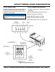
Figure 14. Voltage Change-Over Board
3Ø 240V Configuration
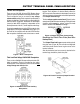
AC Voltmeter Gauge Reading
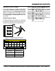
Place the AC Voltmeter Change-Over Switch (Figure 15)
in the W-U position and observe the phase to phase voltage
reading between the W and U terminals as indicated on
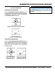
the AC Voltmeter Gauge (Figure 16)
Figure 15. AC Voltmeter Change-Over Switch
Figure 16. AC Voltmeter Gauge
AC Ammeter Gauge Reading
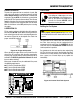
Place the AC AmmeterChange-Over Switch (Figure 17)
to the U position and observe the current reading (load
drain) at the U terminal as indicated on the AC Ammeter
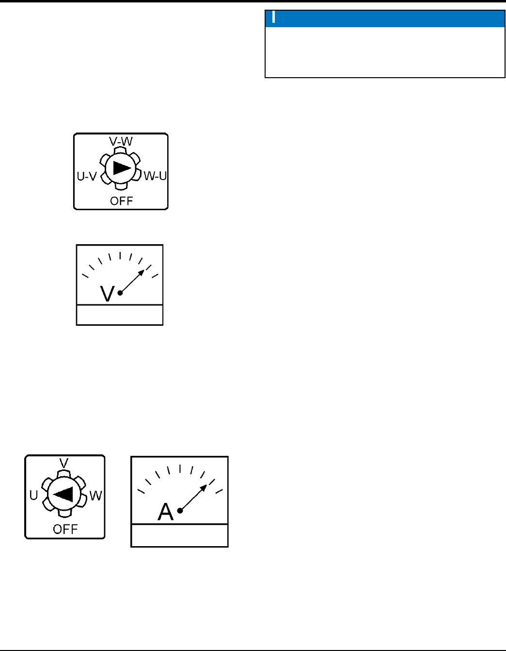
Gauge (Figure 18). This process can be repeated for
terminals V and W.
Figure 17. AC Ammeter
Change-Over Switch
Figure 18. AC Ammeter
(Amp Reading on U Lug)
NOTICE
The ammeter gauge will only show a reading when
the Output Terminal Lugs are connected to a load
and in use.